ACC-1 ENGINE C D E F G H I J K L M SECTION ACC A ACC N O P CONTENTS ACCELERATOR CONTROL SYSTEM PRECAUTION .............................................. 2 PRECAUTIONS .................................................. 2 FOR USA AND CANADA ........................................... 2 FOR USA AND CANADA : Precaution for Supple- mental Restraint System (SRS) "AIR BAG" and "SEAT BELT PRE-TENSIONER" ............................. 2 FOR MEXICO ............................................................. 2 FOR MEXICO : Precaution for Supplemental Re- straint System (SRS) "AIR BAG" and "SEAT BELT PRE-TENSIONER" .................................................. 2 REMOVAL AND INSTALLATION ............... 4 ACCELERATOR CONTROL SYSTEM .............. 4 Exploded View ......................................................... 4 Removal and Installation ......................................... 4 Inspection ................................................................ 5 Revision: 2013 February 2012 ROGUE
ACC-2 < PRECAUTION > PRECAUTIONS PRECAUTION PRECAUTIONS FOR USA AND CANADA FOR USA AND CANADA : Precaution for Supplemental Restraint System (SRS) "AIR BAG" and "SEAT BELT PRE-TENSIONER" INFOID:0000000007737507 The Supplemental Restraint System such as “AIR BAG” and “SEAT BELT PRE-TENSIONER”, used along with a front seat belt, helps to reduce the risk or severity of injury to the driver and front passenger for certain types of collision. This system includes seat belt switch inputs and dual stage front air bag modules. The SRS system uses the seat belt switches to determine the front air bag deployment, and may only deploy one front air bag, depending on the severity of a collision and whether the front occupants are belted or unbelted. Information necessary to service the system safely is included in the “SRS AIR BAG” and “SEAT BELT” of this Service Manual. WARNING: Always observe the following items for preventing accidental activation. • To avoid rendering the SRS inoperative, which could increase the risk of personal injury or death in the event of a collision that would result in air bag inflation, all maintenance must be performed by an authorized NISSAN/INFINITI dealer. • Improper maintenance, including incorrect removal and installation of the SRS, can lead to personal injury caused by unintentional activation of the system. For removal of Spiral Cable and Air Bag Module, see “SRS AIR BAG”. • Never use electrical test equipment on any circuit related to the SRS unless instructed to in this Ser- vice Manual. SRS wiring harnesses can be identified by yellow and/or orange harnesses or harness connectors. PRECAUTIONS WHEN USING POWER TOOLS (AIR OR ELECTRIC) AND HAMMERS WARNING: Always observe the following items for preventing accidental activation. • When working near the Air Bag Diagnosis Sensor Unit or other Air Bag System sensors with the ignition ON or engine running, never use air or electric power tools or strike near the sensor(s) with a hammer. Heavy vibration could activate the sensor(s) and deploy the air bag(s), possibly causing serious injury. • When using air or electric power tools or hammers, always switch the ignition OFF, disconnect the battery, and wait at least 3 minutes before performing any service. FOR MEXICO FOR MEXICO : Precaution for Supplemental Restraint System (SRS) "AIR BAG" and "SEAT BELT PRE-TENSIONER" INFOID:0000000007737570 The Supplemental Restraint System such as “AIR BAG” and “SEAT BELT PRE-TENSIONER”, used along with a front seat belt, helps to reduce the risk or severity of injury to the driver and front passenger for certain types of collision. Information necessary to service the system safely is included in the “SRS AIR BAG” and “SEAT BELT” of this Service Manual. WARNING: Always observe the following items for preventing accidental activation. • To avoid rendering the SRS inoperative, which could increase the risk of personal injury or death in the event of a collision that would result in air bag inflation, all maintenance must be performed by an authorized NISSAN/INFINITI dealer. • Improper maintenance, including incorrect removal and installation of the SRS, can lead to personal injury caused by unintentional activation of the system. For removal of Spiral Cable and Air Bag Module, see “SRS AIR BAG”. • Never use electrical test equipment on any circuit related to the SRS unless instructed to in this Ser- vice Manual. SRS wiring harnesses can be identified by yellow and/or orange harnesses or harness connectors. PRECAUTIONS WHEN USING POWER TOOLS (AIR OR ELECTRIC) AND HAMMERS WARNING: Revision: 2013 February 2012 ROGUE
PRECAUTIONS ACC-3 < PRECAUTION > C D E F G H I J K L M A ACC N P O Always observe the following items for preventing accidental activation. • When working near the Air Bag Diagnosis Sensor Unit or other Air Bag System sensors with the ignition ON or engine running, never use air or electric power tools or strike near the sensor(s) with a hammer. Heavy vibration could activate the sensor(s) and deploy the air bag(s), possibly causing serious injury. • When using air or electric power tools or hammers, always switch the ignition OFF, disconnect the battery, and wait at least 3 minutes before performing any service. Revision: 2013 February 2012 ROGUE
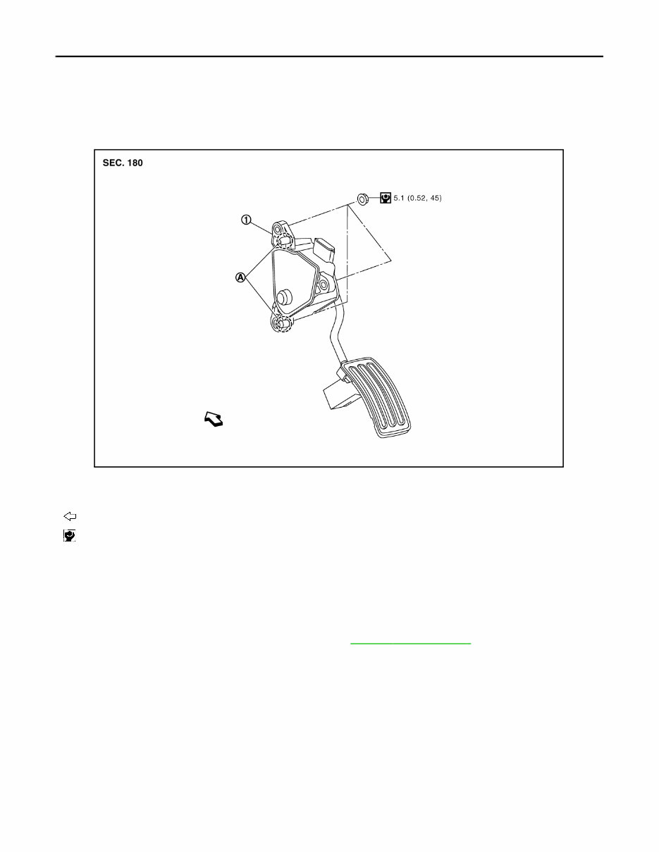
ACC-4 < REMOVAL AND INSTALLATION > ACCELERATOR CONTROL SYSTEM REMOVAL AND INSTALLATION ACCELERATOR CONTROL SYSTEM Exploded View INFOID:0000000007351136 Removal and Installation INFOID:0000000007351137 REMOVAL 1. Disconnect accelerator pedal position sensor harness connector. 2. Remove accelerator pedal assembly mounting nuts. 3. Loosen brake pedal assembly mounting nuts. Refer to BR-19, " Exploded View " . NOTE: Brake pedal assembly does not have to be removed from the vehicle. 4. Remove accelerator pedal assembly. CAUTION: • Never disassemble accelerator lever. Never remove accelerator pedal position sensor from accelerator lever. • Avoid impact from dropping etc. during handling. • Be careful to keep accelerator lever away from water. INSTALLATION Note the following, and install in the reverse order of removal. • Insert locating pin into vehicle side to position accelerator pedal assembly. Tighten mounting nuts to acceler- ator pedal assembly. 1. Accelerator pedal assembly A. Locating pin : Vehicle front : N·m (kg-m, in-lb) JPBIA1270GB Revision: 2013 February 2012 ROGUE
ACCELERATOR CONTROL SYSTEM ACC-5 < REMOVAL AND INSTALLATION > C D E F G H I J K L M A ACC N P O Inspection INFOID:0000000007351138 INSPECTION AFTER INSTALLATION • Check that accelerator pedal moves smoothly within the whole operation range when it is depressed fully and released. • Check that accelerator pedal returns securely to the fully released position. • For the electrical inspection of accelerator pedal position sensor. Refer to the following: - For Mexico: EC-718, " Component Inspection " . - Except for Mexico: EC-374, " Component Inspection " . - CAUTION: When harness connector of accelerator pedal position sensor is disconnected, perform “ACCELEA- TOR PEDAL RELEASED POSITION LEARNING”. Refer to EC-473, " ACCELERATOR PEDAL RELEASED POSITION LEARNING : Description " (for Mexico) or EC-23, " ACCELERATOR PEDAL RELEASED POSITION LEARNING : Description " (Except for Mexico). Revision: 2013 February 2012 ROGUE
The 2013 Nissan Rogue Service & Repair Manual is the ultimate solution for DIY vehicle repairs. This comprehensive manual provides all the necessary troubleshooting and replacement procedures recommended by the manufacturer, complete with step-by-step instructions, clear images, and exploded-view illustrations.
While the durability of your Nissan Rogue is unquestionable, regular maintenance is essential for its longevity. And with time, certain parts may wear out and need to be replaced. With this service & repair manual, you'll have access to the manufacturer's recommended charts and procedures, allowing you to fix your vehicle with ease.
Gone are the days of flipping through hundreds of pages or losing greasy, torn, or misplaced pages. The digital format of this manual allows for easy searching, bookmarking, and even screenshotting for quick reference. Whether you prefer a physical copy or a digital version, this manual has you covered.
Compatible with a wide range of electronic devices and easily printable, the 2013 Nissan Rogue Service & Repair Manual is a convenient and reliable resource for all your repair needs. Keep your vehicle running smoothly and save on repair costs with this must-have manual.
Printable: Yes Language: English Compatibility: PC & Mac computers, Android and Apple smartphones & tablets, and more. Requirements: Adobe Reader (free)