ENGINE MECHANICAL SECTION EM MODIFICATION NOTICE: Gasoline engine: I KA24DE engine information has been added. Diesel engine: I The main bearing clearance has been changed. I The exhaust valve identification mark has been changed. I The piston ring identification mark has been changed. I The tightening torque has been changed on bolts and nuts for the engine slinger, crankshaft pulley and flywheel. I A washer has been added between the glow plate and the glow plug. CONTENTS KA24DE PRECAUTIONS AND PREPARATION............................2 Parts Requiring Angular Tightening .............................2 Liquid Gasket Application Procedure ..........................2 Special Service Tools ..................................................3 Commercial Service Tools ...........................................6 OUTER COMPONENT PARTS .......................................7 COMPRESSION PRESSURE........................................10 Measurement of Compression Pressure ...................10 OIL PAN ......................................................................... 11 Removal ..................................................................... 11 Installation ..................................................................12 TIMING CHAIN ..............................................................13 Removal .....................................................................15 Inspection...................................................................17 Installation ..................................................................18 OIL SEAL REPLACEMENT ..........................................21 CYLINDER HEAD..........................................................24 Removal .....................................................................25 Installation ..................................................................25 Disassembly...............................................................26 Inspection...................................................................26 Assembly ...................................................................32 Valve Clearance.........................................................32 ENGINE REMOVAL .......................................................35 Removal .....................................................................36 Installation ..................................................................37 CYLINDER BLOCK .......................................................38 Disassembly...............................................................39 Inspection...................................................................39 Assembly ...................................................................45 QD & TD OUTER COMPONENT PARTS .....................................49 CYLINDER HEAD..........................................................50 Assembly ...................................................................51 ENGINE OVERHAUL ....................................................52 Assembly ...................................................................54 KA24DE SERVICE DATA AND SPECIFICATIONS (SDS) ..........55 General Specifications ...............................................55 Inspection and Adjustment ........................................55 QD & TD SERVICE DATA AND SPECIFICATIONS (SDS) ..........63 Inspection and Adjustment ........................................63 GI MA LC EC FE CL MT AT TF PD FA RA BR ST RS BT HA EL IDX EM-1
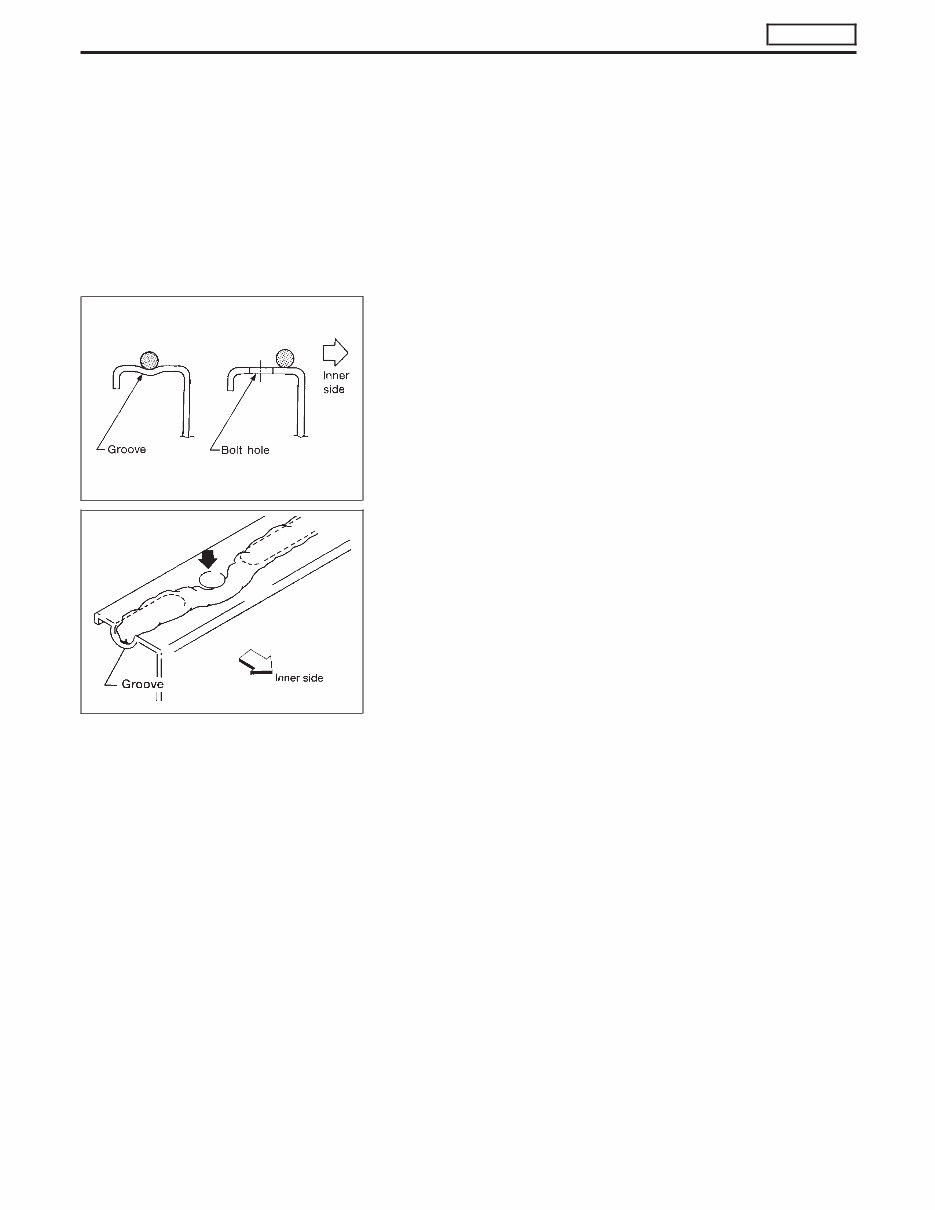
Parts Requiring Angular Tightening I Use an angle wrench for the final tightening of the following engine parts: (1) Cylinder head bolts (2) Connecting rod cap nuts I Do not use a torque value for final tightening. I The torque values for these parts are for a preliminary step. I Ensure thread and seat surfaces are clean and coated with engine oil. Liquid Gasket Application Procedure a. Use a scraper to remove all traces of old liquid gasket from mating surfaces and grooves. Also, completely clean any oil from these areas. b. Apply a continuous bead of liquid gasket to mating sur- faces. (Use Genuine Liquid Gasket or equivalent.) I For oil pan, be sure liquid gasket diameter is 3.5 to 4.5 mm (0.138 to 0.177 in). I For areas except oil pan, be sure liquid gasket diameter is 2.0 to 3.0 mm (0.079 to 0.118 in). c. Apply liquid gasket around the inner side of bolt holes (unless otherwise specified). d. Assembly should be done within 5 minutes after coating. e. Wait at least 30 minutes before refilling engine oil and engine coolant. SEM164F AEM080 PRECAUTIONS AND PREPARATION KA24DE EM-2
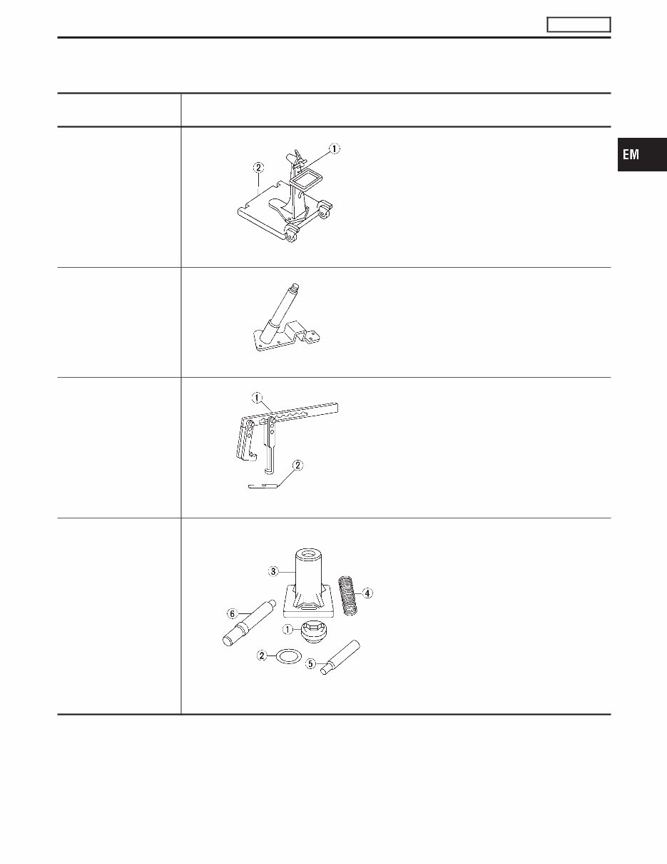
Special Service Tools *: Special tool or commercial equivalent Tool number Tool name Description ST0501S000* Engine stand assembly q 1 ST05011000 Engine stand q 2 ST05012000 Base NT042 Disassembling and assembling KV10105001* Engine attachment NT031 KV101092S0* Valve spring compressor q 1 KV10109210 Compressor q 2 KV10109220 Adapter NT021 Disassembling and assembling valve compo- nents) KV10110300 Piston pin press stand assembly q 1 KV10110310 Cap q 2 KV10110330 Spacer q 3 ST13030020 Press stand q 4 ST13030030 Spring q 5 KV10110340 Drift q 6 KV10110320 Center shaft NT036 Disassembling and assembling piston with connecting rod PRECAUTIONS AND PREPARATION KA24DE EM-3 GI MA LC EC FE CL MT AT TF PD FA RA BR ST RS BT HA EL IDX
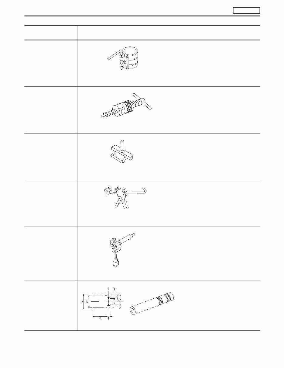
Tool number Tool name Description EM03470000* Piston ring compressor NT044 Installing piston assembly into cylinder bore ST16610001* Pilot bushing puller NT045 Removing crankshaft pilot bushing KV10111100 Seal cutter NT046 Removing oil pan WS39930000* Tube presser NT052 Pressing the tube of liquid gasket KV10112100 Angle wrench NT014 Tightening bolts for bearing cap, cylinder head, etc. KV10116300 Valve oil seal drift NT602 Installing valve oil seal a: 25 (0.98) dia. b: 14.4 (0.567) dia. c: 11.8 (0.465) dia. d: 10 (0.39) dia. e: 11 (0.43) f : 9 (0.35) Unit: mm (in) PRECAUTIONS AND PREPARATION KA24DE Special Service Tools (Cont’d) EM-4
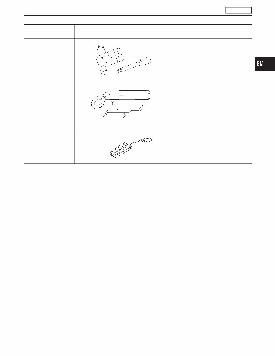
Tool number Tool name Description ST10120000 Cylinder head bolt wrench NT583 Loosening and tightening cylinder head bolt a: 13 (0.51) dia. b: 12 (0.47) c: 10 (0.39) Unit: mm (in) KV101151S0 Lifter stopper set q 1 KV10115110 Camshaft pliers q 2 KV10115120 Lifter stopper NT041 Changing valve lifter shims KV10105800* Chain stopper NT010 Removing and installing idler sprocket PRECAUTIONS AND PREPARATION KA24DE Special Service Tools (Cont’d) EM-5 GI MA LC EC FE CL MT AT TF PD FA RA BR ST RS BT HA EL IDX
The 1997-2011 Nissan Navara Service & Repair Manual is a comprehensive guide tailored for Nissan Navara vehicles manufactured between 1997 and 2011. It offers detailed information and step-by-step instructions for servicing and repairing your vehicle.
This manual equips you to perform routine maintenance tasks like oil changes, brake pad replacements, and air filter replacements. Additionally, it provides detailed instructions for more complex repairs, including engine and transmission overhauls.
Whether you are a professional mechanic or a DIY enthusiast, this manual is a valuable resource for maintaining your Nissan Navara in top condition. It covers a wide range of models, including:
1997 Nissan Navara
1998 Nissan Navara
1999 Nissan Navara
2000 Nissan Navara
2001 Nissan Navara
2002 Nissan Navara
2003 Nissan Navara
2004 Nissan Navara
2005 Nissan Navara
2006 Nissan Navara
2007 Nissan Navara
2008 Nissan Navara
2009 Nissan Navara
2010 Nissan Navara
2011 Nissan Navara
Don't wait until something goes wrong with your Nissan Navara. Take proactive steps to keep it running smoothly with the help of the 1997-2011 Nissan Navara Service & Repair Manual.