Description GUID-6273B329-770B-4108-984C-855D7FAB6E4A This volume explains “Removal, Disassembly, Installation, Inspection and Adjustment” and “Trouble Diagnoses”.
Terms GUID-E00C7B4A-815E-4460-8629-03DEC7104AC2 The captions WARNING and CAUTION warn you of steps that must be followed to prevent personal injury and/or damage to some part of the vehicle. WARNING indicates the possibility of personal injury if instructions are not followed. CAUTION indicates the possibility of component damage if instructions are not followed. BOLD TYPED STATEMENTS except WARNING and CAUTION give you helpful information. Standard value: Tolerance at inspection and adjustment. Limit value: The maximum or minimum limit value that should not be exceeded at inspection and adjustment.
Units GUID-12812BCC-5809-46E1-BBD2-BB0139598F40 The UNITS given in this manual are primarily expressed as the SI UNIT (International System of Unit), and alternatively expressed in the metric system and in the yard/pound system. Also with regard to tightening torque of bolts and nuts, there are descriptions both about range and about the standard tightening torque. “Example” Range Outer Socket Lock Nut : 59 - 78 N·m (6.0 - 8.0 kg-m, 43 - 58 ft-lb) Standard Drive Shaft Installation Bolt : 44.3 N·m (4.5 kg-m, 33 ft-lb)
Contents GUID-E92349BB-13B6-4F16-B2B8-BA52606A8BA0 THE CONTENTS are listed on the first page of each section. THE TITLE is indicated on the upper portion of each page and shows the part or system. THE PAGE NUMBER of each section consists of two or three letters which designate the particular section and a number (e.g. “BR-5”). THE SMALL ILLUSTRATIONS show the important steps such as inspection, use of special tools, knacks of work and hidden or tricky steps which are not shown in the previous large illustrations. Assembly, inspection and adjustment procedures for the complicated units such as the automatic transaxle or transmission, etc. are presented in a step-by-step format where necessary.
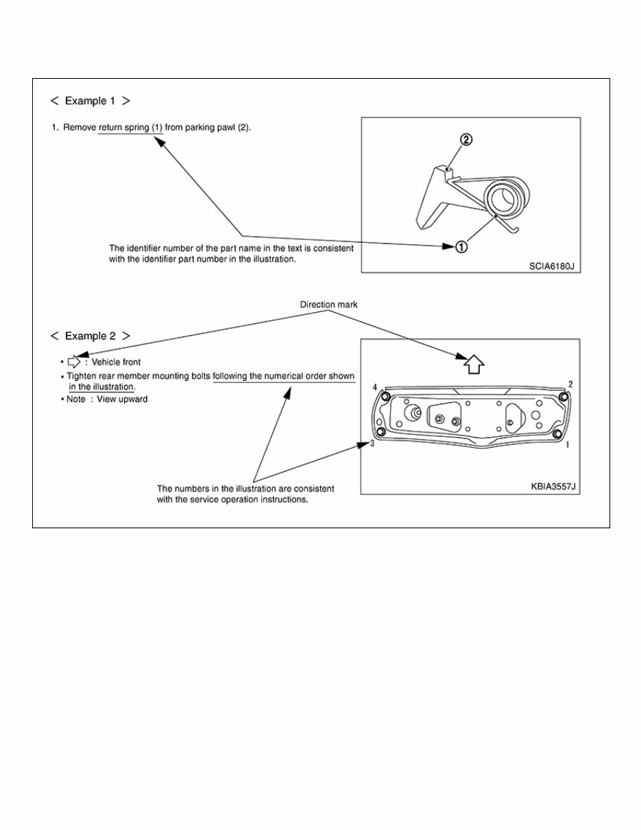
Relation between Illustrations and Descriptions GUID-EBA9621C-85DD-4A21-B714-5FCC0116494A The following sample explains the relationship between the part description in an illustration, the part name in the text and the service procedures. GUID-NISSAIA0519E
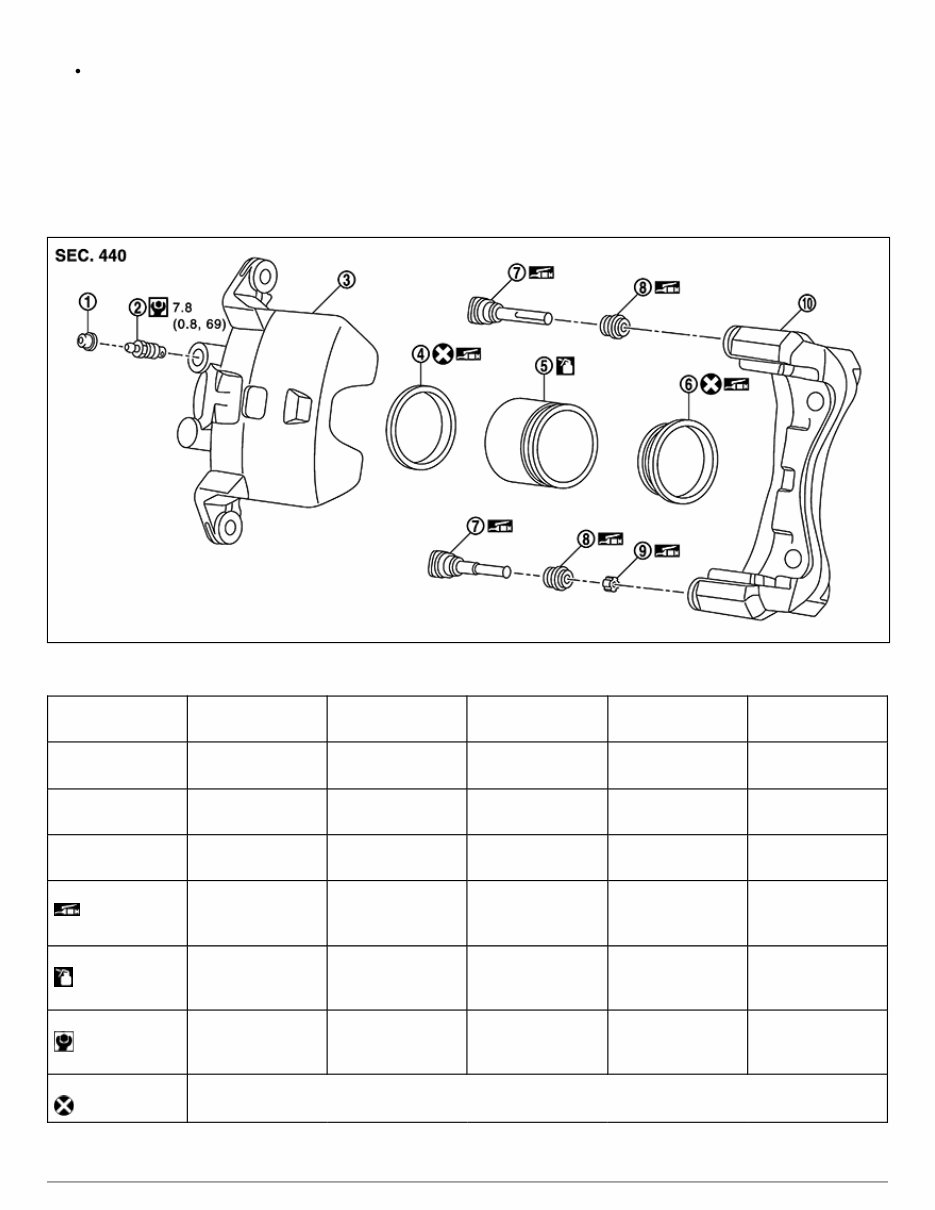
Components GUID-D3DEE506-831B-42D0-8DB7-07EC496B08FD THE LARGE ILLUSTRATIONS are exploded views (see the following) and contain tightening torques, lubrication points, section number of the PARTS CATALOG (e.g. SEC. 440) and other information necessary to perform repairs. The illustrations should be used in reference to service matters only. When ordering parts, refer to the appropriate PARTS CATALOG. Components shown in an illustration may be identified by a circled number. When this style of illustration is used, the text description of the components will follow the illustration. GUID-NISJPFIA0511GB 1. Cap 2. Bleeder valve 3. Cylinder body 4. Piston seal 5. Piston 6. Piston boot 7. Sliding pin 8. Sliding pin boot 9. Bushing 10. Torque member : Apply rubber grease. : Apply brake fluid. : N·m (kg-m, in-lb) : Always replace after every disassembly SYMBOLS
GUID-NISSAIA0749E
Description GUID-3A55698F-011E-4AA7-8275-197BB88255B7 Note: Trouble diagnoses indicate work procedures required to diagnose problems effectively. Observe the following instructions before diagnosing: Before performing trouble diagnoses, read the “Work Flow” in each section. After repairs, re-check that the problem has been completely eliminated. Refer to Component Parts and Harness Connector Location for the Systems described in each section for identification/location of components and harness connectors. When checking circuit continuity, ignition switch should be OFF. Refer to the Circuit Diagram for quick pinpoint check. If you need to check circuit continuity between harness connectors in more detail, such as when a sub-harness is used, refer to Wiring Diagram in each individual section and Harness Layout in PG section for identification of harness connectors. Before checking voltage at connectors, check battery voltage. After accomplishing the Diagnosis Procedures and Electrical Components Inspection, check that all harness connectors are reconnected as they were.
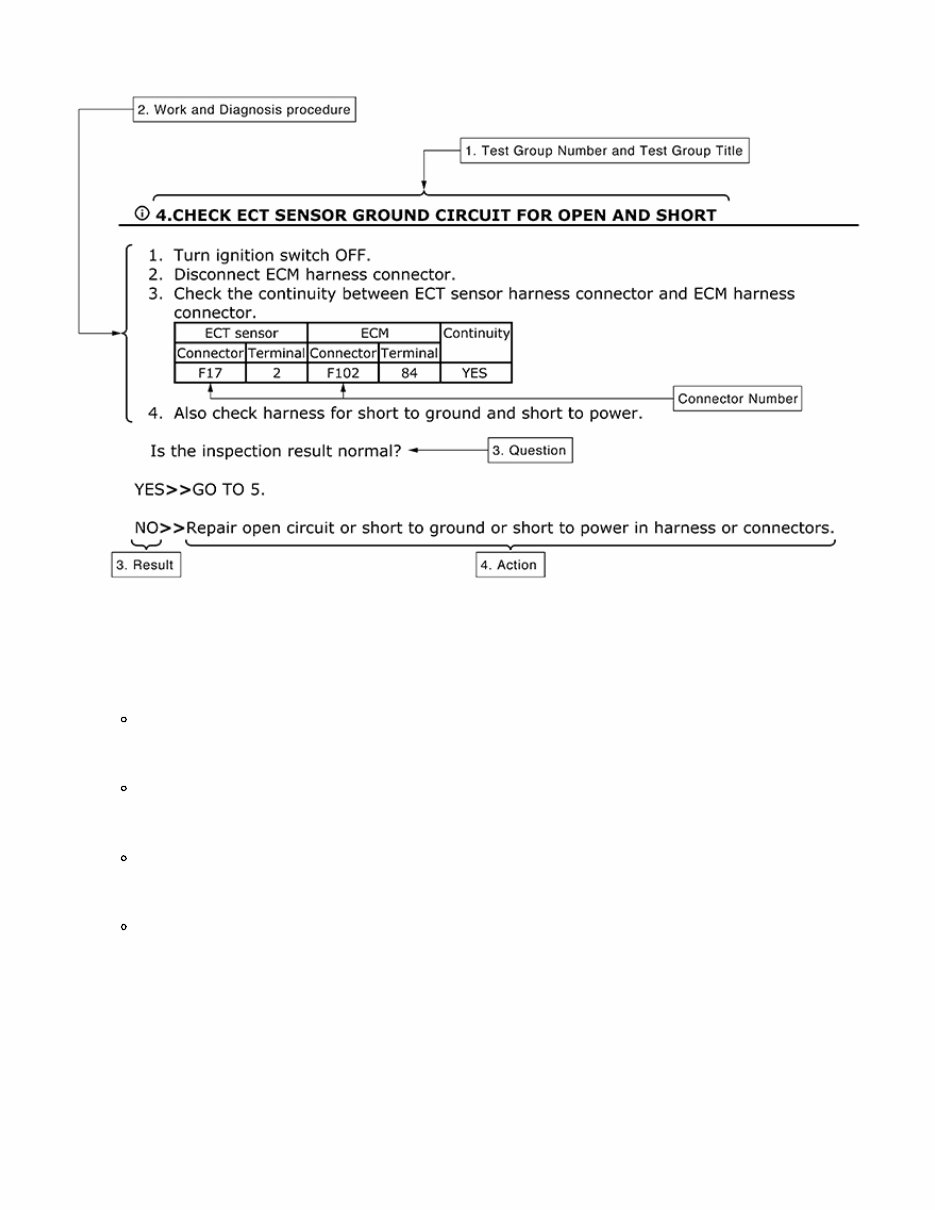
How to Follow Test Groups in Trouble Diagnosis GUID-3C4C1D41-250C-4E78-A785-222F4EB96078 GUID-TGALAIA0017GB 1. Test group number and test group title Test group number and test group title are shown in the upper portion of each test group. 2. Work and diagnosis procedure Start to diagnose a problem using procedures indicated in enclosed test groups. 3. Questions and results Questions and required results are indicated in test group. 4. Action Next action for each test group is indicated based on result of each question.
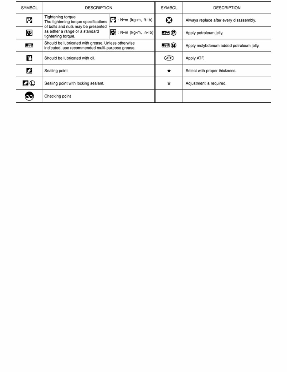
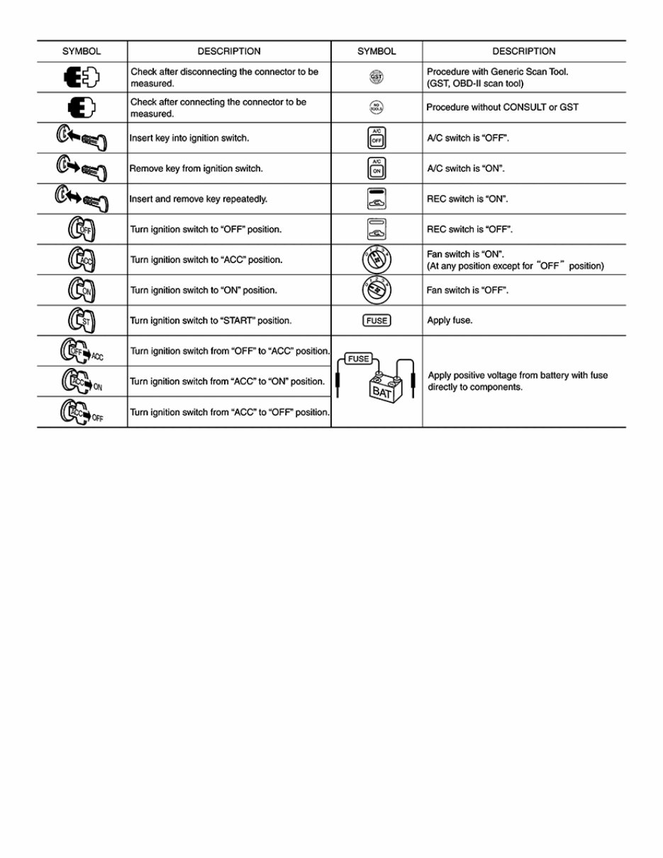
Key to Symbols Signifying Measurements or Procedures GUID-F6EBD551-8F17-4B66-BBDD-A3F6169993A2 GUID-NISJPAIA0982GB
Easily fix any issues with your 2022 Nissan Murano using this comprehensive service & repair manual. It is packed with the manufacturer's recommended troubleshooting charts and replacement procedures, making it the ultimate DIY guide for your vehicle.
Regular maintenance is essential for keeping your vehicle in top shape, and this manual provides all the necessary information to ensure its durability. Even as parts wear out over time, the step-by-step instructions, clear images, and exploded-view illustrations in this manual will help you replace them with ease.
Forget about flipping through hundreds of pages or dealing with greasy, torn, or lost pages. This digital manual can be easily accessed on any electronic device, including PC and Mac computers, smartphones, and tablets. It is also printable, giving you the option to have a physical copy.
Don't let car troubles keep you in the repair shop for long periods. With this service & repair manual, you can save on repairs, increase your vehicle's reliability, and have the confidence to fix any issue that arises. Get your hands on the 2022 Nissan Murano service & repair manual and take control of your vehicle's maintenance needs.
Comprehensive repair manual for 2022 Nissan Murano
Includes troubleshooting charts and replacement procedures recommended by the manufacturer
Step-by-step instructions, clear images, and exploded-view illustrations
Digital format compatible with various devices
Printable option also available
Save on repair costs and increase vehicle reliability
Don't wait until it's too late - get your 2022 Nissan Murano service & repair manual now and stay ahead of any car troubles that may come your way.