Precaution for Supplemental Restraint System (SRS) "AIR BAG" and "SEAT BELT PRE-TENSIONER" The Supplemental Restraint System such as “AIR BAG” and “SEAT BELT PRE-TENSIONER”, used along with a front seat belt, helps to reduce the risk or severity of injury to the driver and front passenger for certain types of collision. Information necessary to service the system safely is included in the SR and SB section of this Service Manual. WARNING: To avoid rendering the SRS inoperative, which could increase the risk of personal injury or death in the event of a collision which would result in air bag inflation, it is recommended that all maintenance and repair be performed by an authorized NISSAN/INFINITI dealer. Improper repair, including incorrect removal and installation of the SRS, can lead to personal injury caused by unintentional activation of the system. For removal of Spiral Cable and Air Bag Module, see the SR section. Do not use electrical test equipment on any circuit related to the SRS unless instructed to in this Service Manual. SRS wiring harnesses can be identified by yellow and/or orange harnesses or harness connectors. PRECAUTIONS WHEN USING POWER TOOLS (AIR OR ELECTRIC) AND HAMMERS WARNING: When working near the Air Bag Diagnosis Sensor Unit or other Air Bag System sensors with the Ignition ON or engine running, DO NOT use air or electric power tools or strike near the sensor(s) with a hammer. Heavy vibration could activate the sensor(s) and deploy the air bag(s), possibly causing serious injury. When using air or electric power tools or hammers, always switch the Ignition OFF, disconnect the battery or batteries, and wait at least three minutes before performing any service.
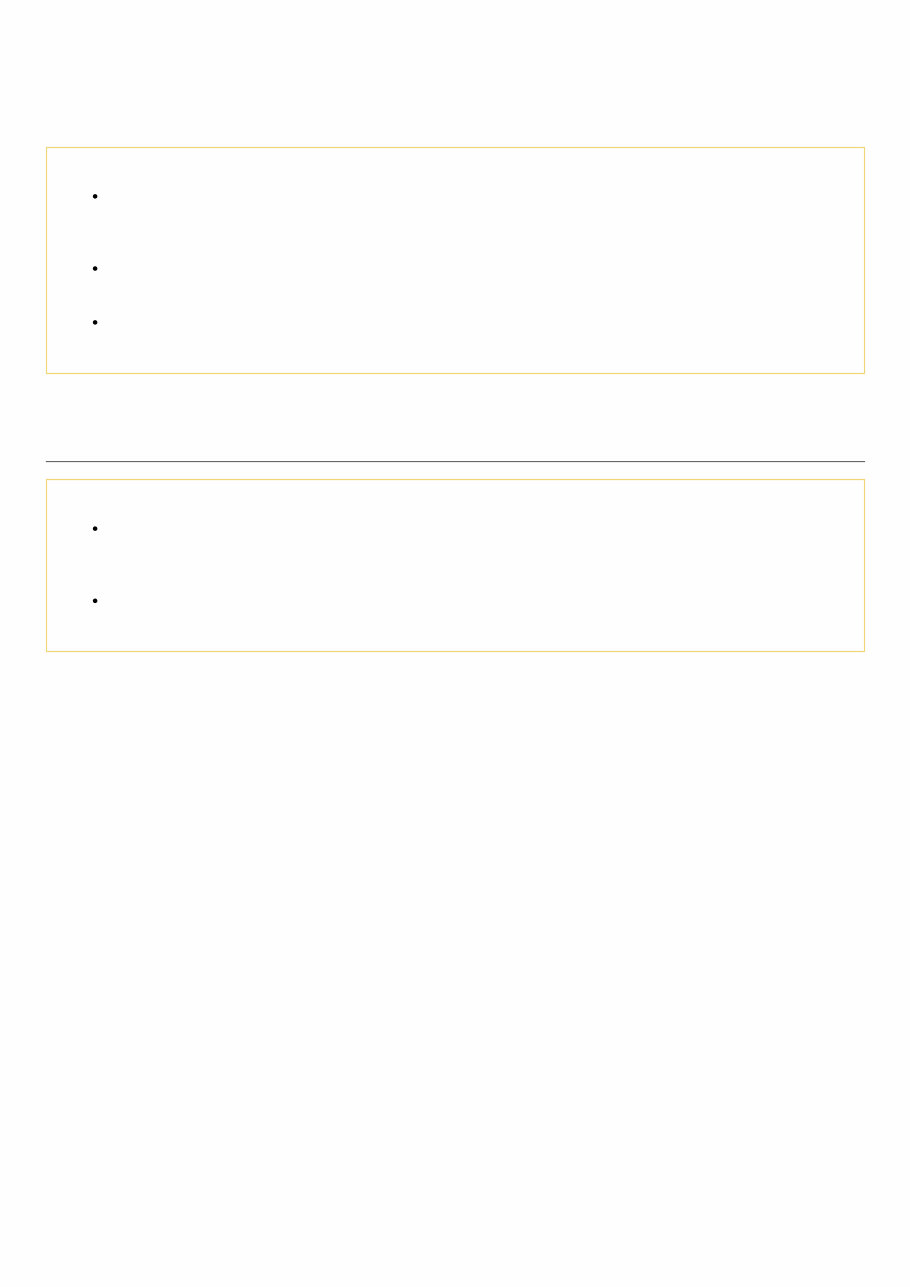
Precaution for Procedure without Cowl Top Cover When performing the procedure after removing cowl top cover, cover the lower end of windshield with urethane, etc. to prevent damage to windshield. NIS0000000011219897-01-PIIB3706J
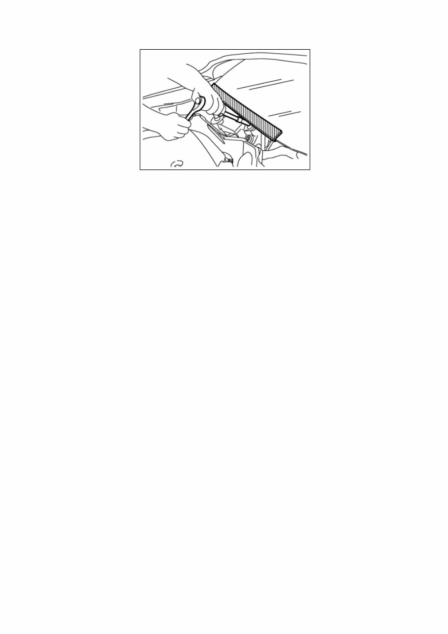
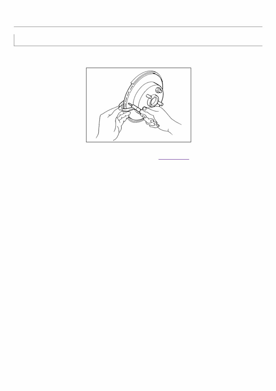
Precaution for Brake System WARNING: Clean any dust from the front brake and rear brake using a vacuum dust collector. Do not blow by compressed air. Brake fluid use refer to Fluids and Lubricants . Do not reuse drained brake fluid. Do not spill or splash brake fluid on painted surfaces. Brake fluid may seriously damage paint. Wipe it off immediately and wash with water if it gets on a painted surface. Always clean with new brake fluid when cleaning the master cylinder, brake caliper and other components. Do not use mineral oils such as gasoline or light oil to clean. They may damage rubber parts and cause improper operation. Always loosen the brake tube flare nut with a flare nut wrench. Tighten the brake tube flare nut to the specified torque with crowfoot (A) and torque wrench (B). NIS0000000011219898-01-JPFIA0001ZZ Always confirm the specified tightening torque when installing the brake pipes. Turn the ignition switch OFF and disconnect the ABS actuator and electric unit (control unit) connector or the battery negative terminal before performing the work. Always connect the battery terminal when moving the vehicle. Check that no brake fluid leakage is present after replacing the parts. Check for bends, cracks and damage to the brake pedal. Adjust brake pedal if it is outside the standard value. Burnish the brake contact surfaces after refinishing or replacing rotors, after replacing pads, or if a soft pedal occurs at very low mileage. Front brake: refer to Inspection and Adjustment. Rear brake: refer to Inspection and Adjustment.
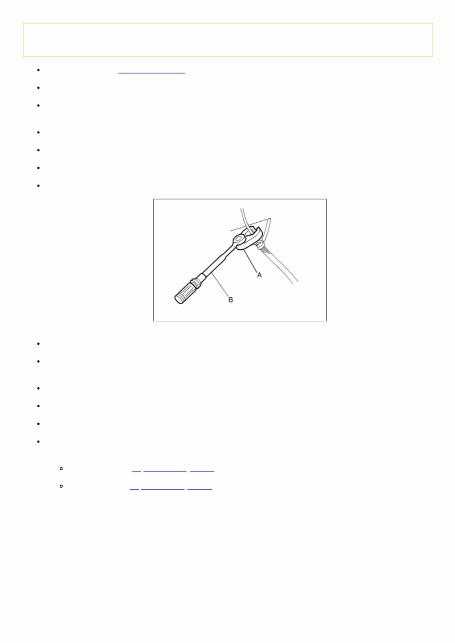
Special Service Tool NIS0000000011219899 The actual shape of the tools may differ from those illustrated here. Tool number (TechMate No.) Tool name Description — (J-46532) Brake height tool NIS0000000011219899-01-FIA0227E Measuring brake pedal height 38-PFM92 ( — ) ProCut™PFM Series Lathe NIS0000000011219899-02- LFIA0092ZZ Refinishing rotors
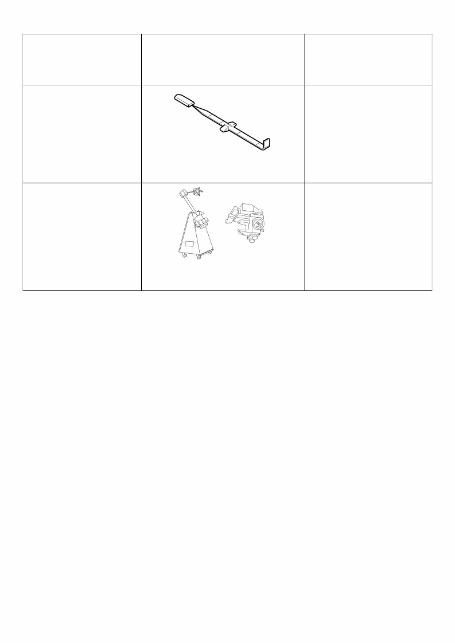
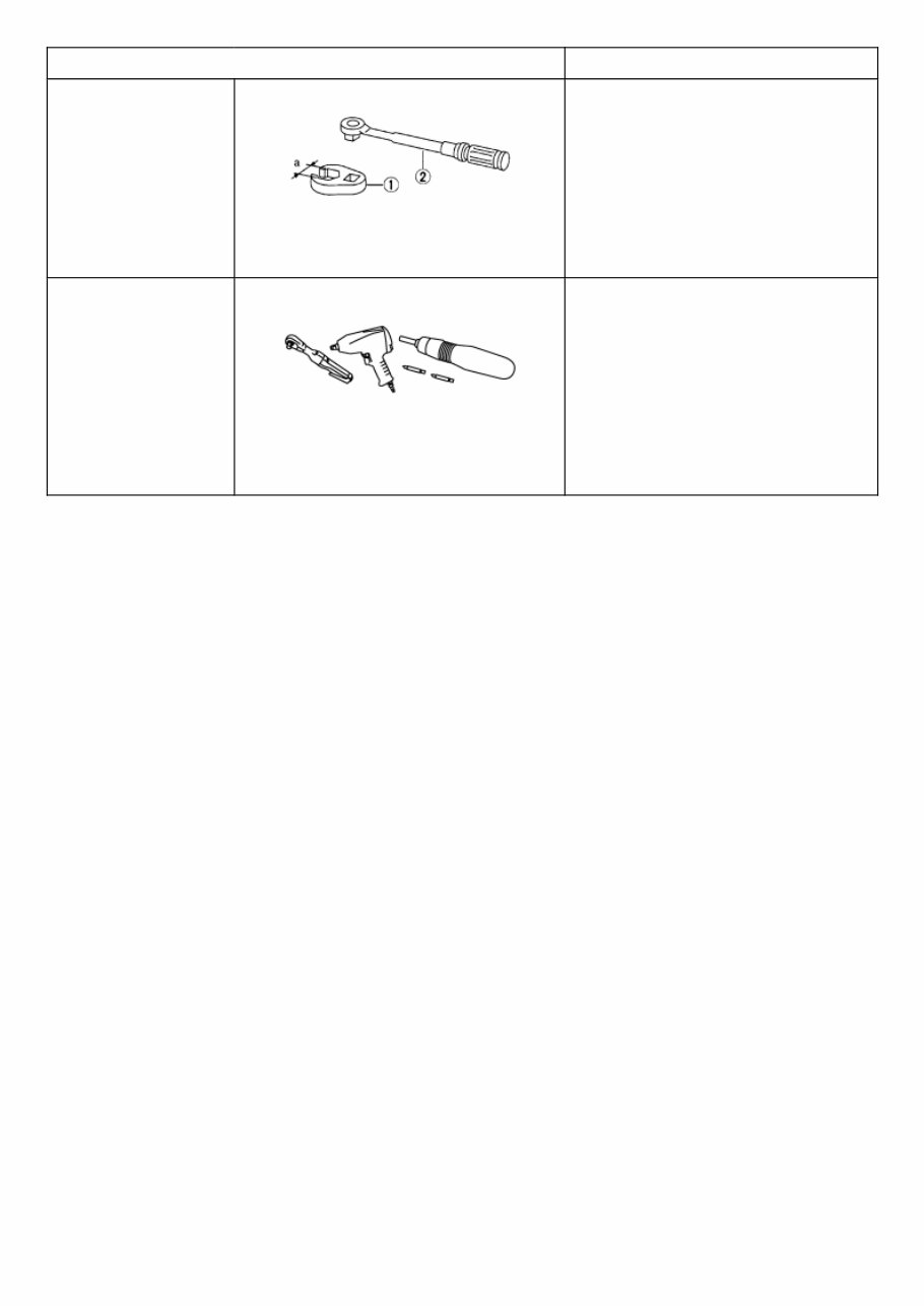
Commercial Service Tool Tool name Description 1. Flare nut crowfoot 2. Torque wrench NIS0000000011219900-01-S-NT360 Tightening brake tube flare nuts a: 10 mm (0.39 in)/12 mm (0.47 in) Power tool NIS0000000011219900-02- PIIB1407E Loosening nuts, screws and bolts
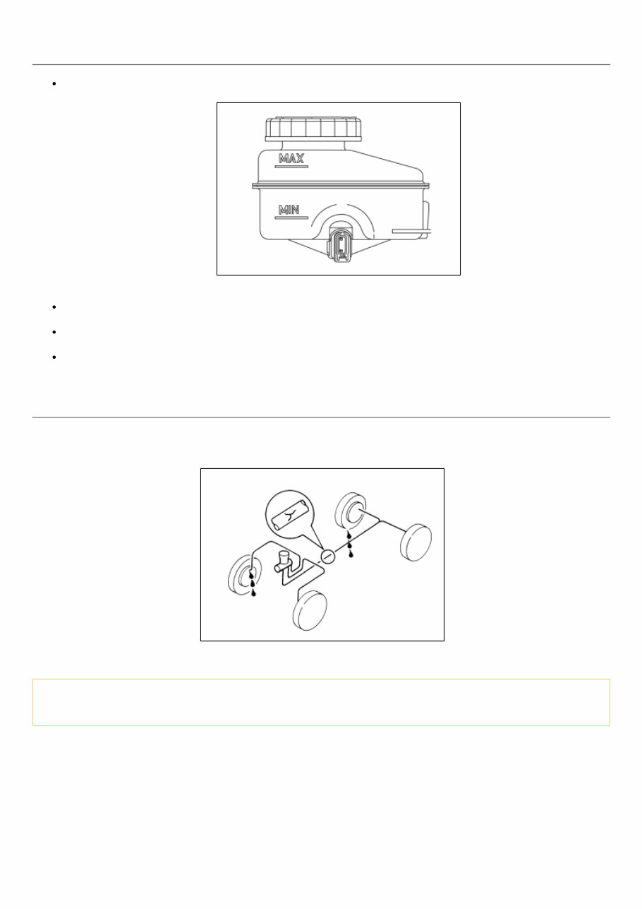
Inspection NIS0000000011219903 BRAKE FLUID LEVEL Make sure that the brake fluid level in the sub tank is between the MAX and MIN lines. NIS0000000011219903-01-LFIA0249ZZ Visually check around the sub tank and reservoir tank for brake fluid leakage. If the brake fluid level is excessively low, check the brake system for leakage. If brake warning lamp remains illuminated after parking brake pedal is released, check the brake system for brake fluid leakage. BRAKE LINE 1 Check brake line (tubes and hoses) for cracks, deterioration or other damage. Replace any damaged parts. 2 Check for brake fluid leakage by fully depressing brake pedal while engine is running. NIS0000000011219903-02-BR389C CAUTION: If brake fluid leakage occurs around joints, retighten or replace damaged parts as necessary.
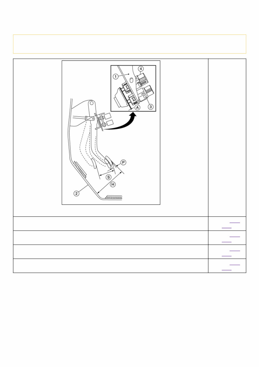
Inspection NIS0000000011219902 BRAKE PEDAL HEIGHT Check the brake pedal height (H) between the dash lower panel (2) and the brake pedal upper surface. CAUTION: Check the brake pedal height with the floor trim removed. NIS0000000011219902-01-WFIA1044ZZ Brake pedal height (H) from dash lower panel (2) Refer to Brake Pedal. Clearance (A) between brake pedal bracket (1), stop lamp switch (4) and brake pedal position switch (3) contact ends Refer to Brake Pedal. Brake pedal full stroke (S) Refer to Brake Pedal. Brake pedal play (P) Refer to Brake Pedal.
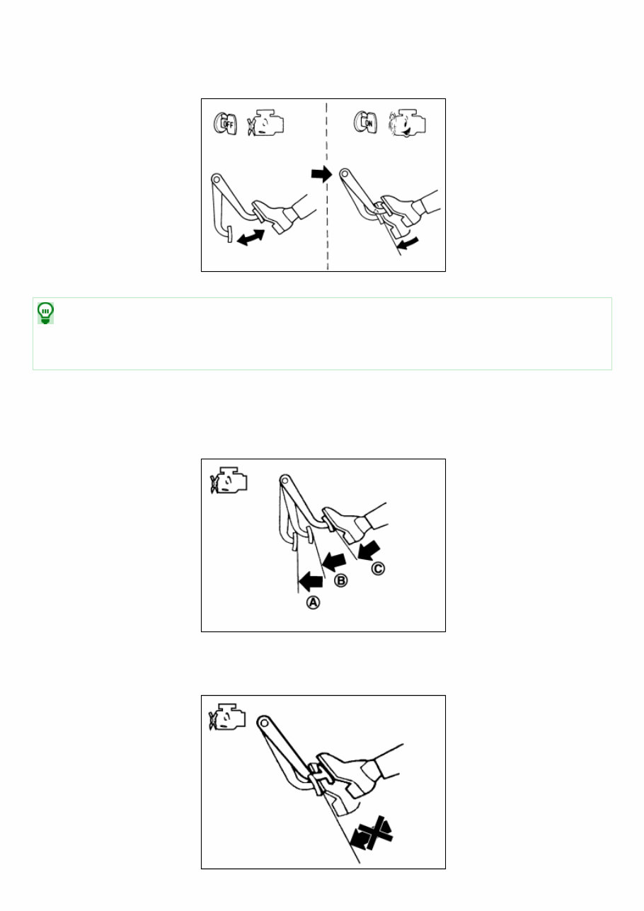
Inspection NIS0000000011219905 Operation Depress the brake pedal several times at five second intervals with the engine stopped. Start the engine with the brake pedal fully depressed. Check that the clearance between brake pedal and dash lower panel decreases. NIS0000000011219905-01-RA0037D NOTE: A slight impact with a small click may be felt on the pedal when the brake pedal is fully depressed. This is normal brake system operation. Vacuum Inspection Idle the engine for one minute to apply vacuum to the brake booster. Stop the engine. Depress the brake pedal several times at five second intervals until the accumulated vacuum is released to atmospheric pressure. Check that the clearance between brake pedal and dash lower panel gradually increases (A → B → C) each time the brake pedal is depressed during this operation. NIS0000000011219905-02-PFIA0043ZZ Depress the brake pedal with the engine running. Then stop the engine while holding down the brake pedal. Check that the brake pedal stroke does not change after holding down the brake pedal for 30 seconds or more. NIS0000000011219905-03-PFIA0044ZZ
NOTE: A slight impact with a small click may be felt on the pedal when the brake pedal is fully depressed. This is normal brake system operation.
Inspection INSPECTION Uneven wear Check for uneven wear of the disc brake rotor using a micrometer. Replace the disc brake rotor if the thickness is below the wear limit. NIS0000000013193746-01-SBR020B Thickness variation (measured at 8 positions) : Refer to Rear Disc Brake.
Easily solve any issues with your 2014 Nissan Murano by using this comprehensive repair manual. It includes all the necessary troubleshooting and replacement procedures provided by the manufacturer, with detailed instructions, clear images, and exploded-view illustrations.
Regular maintenance is crucial for maintaining your vehicle's top condition, and this manual provides the manufacturer's recommended charts and procedures. By following these guidelines, you can save on repairs, increase reliability, and avoid frequent trips to the repair shop.
Conveniently access this manual on any electronic device, such as PC and Mac computers, smartphones, and tablets. No more flipping through pages or worrying about losing or damaging them. You can easily search, bookmark, and take screenshots for the information you need.
If you prefer a physical copy, you can always print it. This manual is compatible with most electronic devices and only requires Adobe Reader (available for free) to view.
Do not let car troubles hinder your progress. With this 2014 Nissan Murano repair manual, you will have all the necessary information to keep your vehicle running smoothly and efficiently.