Precaution for Supplemental Restraint System (SRS) "AIR BAG" and "SEAT BELT PRE-TENSIONER" RDE-001020313 The Supplemental Restraint System such as “AIR BAG” and “SEAT BELT PRE-TENSIONER”, used along with a front seat belt, helps to reduce the risk or severity of injury to the driver and front passenger for certain types of collisions. Information necessary to service the system safely is included in the “SRS AIR BAG” and “SEAT BELT” sections of this Service Manual. WARNING: Always observe the following items for preventing accidental activation: To avoid rendering the SRS inoperative, which could increase the risk of personal injury or death in the event of a collision that would result in air bag inflation, it is recommended that all maintenance and repair be performed by an authorized NISSAN/INFINITI dealer. Improper repair, including incorrect removal and installation of the SRS, can lead to personal injury caused by unintentional activation of the system. For removal of Spiral Cable and Air Bag Module, see “SRS AIR BAG”. Never use electrical test equipment on any circuit related to the SRS unless instructed to in this Service Manual. SRS wiring harnesses can be identified by yellow and/or orange harnesses or harness connectors. PRECAUTIONS WHEN USING POWER TOOLS (AIR OR ELECTRIC) AND HAMMERS WARNING: Always observe the following items for preventing accidental activation: When working near the Air Bag Diagnosis Sensor Unit or other Air Bag System sensors with the ignition/power switch ON or engine running, never use air or electric power tools or strike near the sensor(s) with a hammer. Heavy vibration could activate the sensor(s) and deploy the air bag(s), possibly causing serious injury. When using air or electric power tools or hammers, always switch the ignition/power switch OFF, disconnect the 12V battery or batteries, and wait at least 3 minutes before performing any service.
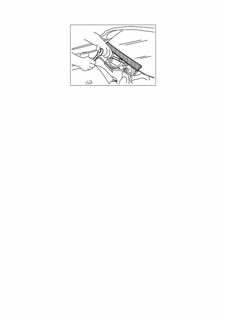
Precaution for Procedure without Cowl Top Cover When performing the procedure after removing cowl top cover, cover the lower end of windshield with urethane, etc to prevent damage to windshield. NISB0000000014660076-01-PIIB3706J
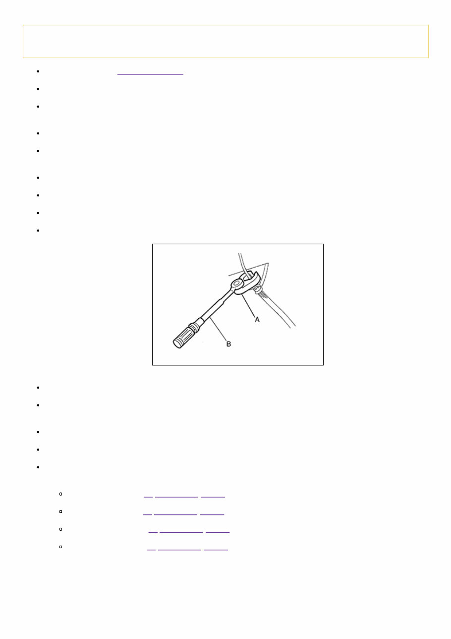
Precaution for Brake System RDE-001020302 WARNING: Clean any dust from the front and rear brakes with a vacuum dust collector. Do not blow with compressed air. Brake fluid use refer to Fluids and Lubricants. Do not reuse drained brake fluid. Do not spill or splash brake fluid on painted surfaces. Brake fluid may seriously damage paint. Wipe it off immediately and wash with water if it gets on a painted surface. If the brake fluid or grease adheres to the disc rotor, quickly wipe it off. After pressing the brake pedal more deeply or harder than normal driving, such as air bleeding, check each item of brake pedal. Adjust brake pedal if it is outside the standard value. Always clean with new brake fluid when cleaning the master cylinder, brake caliper and other components. Do not use mineral oils such as gasoline or light oil to clean. They may damage rubber parts and cause improper operation. Always loosen the brake tube flare nut with a flare nut wrench. Tighten the brake tube flare nut to the specified torque using a crowfoot (A) and a torque wrench (B). RDE-001020302-01-PFIA0001ZZ Always confirm the specified tightening torque when installing the brake pipes. Brake component parts are critical safety parts. If a brake fluid leak is detected, always disassemble the affected part. If a malfunction is detected, replace part with a new one. Turn the ignition switch OFF and battery negative terminal before performing the work. Check that no brake fluid leakage is present after replacing the parts. Burnish the brake contact surfaces after refinishing or replacing rotors, after replacing pads, or if a soft pedal occurs at very low mileage. Front brake pad: refer to Inspection and Adjustment. Front disc rotor: refer to Inspection and Adjustment. Rear brake lining: refer to Inspection and Adjustment. Rear brake drum: refer to Inspection and Adjustment.
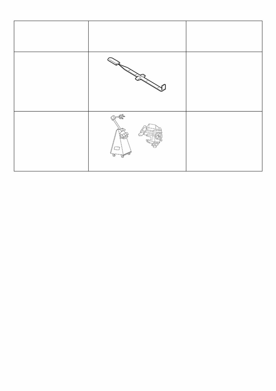
Special Service Tool RDE-001020329 The actual shape of the tools may differ from those illustrated here. Tool number (TechMate No.) Tool name Description — (J-46532) Brake height tool RDE-001020329-01-FIA0227E Measuring brake pedal height 38-PFM92 ( — ) Pro-Cut™ PFM Series Lathe RDE-001020329-02-LFIA0092ZZ Refinishing rotors
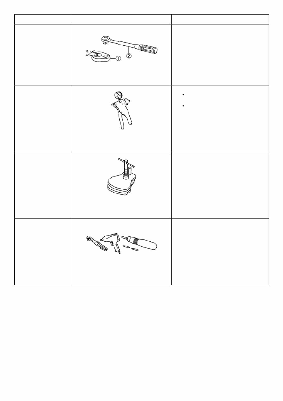
Commercial Service Tool Tool name Description 1. Flare nut crowfoot 2. Torque wrench NISB0000000014660079-01-NT360 Tightening brake tube flare nuts a: 10 mm (0.39 in) / 12 mm (0.47 in) Handy vacuum pump NISB0000000014660079-02- ZZC1313D Air tight Inspection of check valve Brake caliper wrench NISB0000000014660079-03- NNFIA0040ZZ Return the piston Power tool NISB0000000014660079-04- PIIB1407E Loosening nuts, screws and bolts
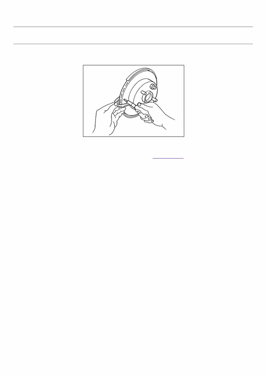
Inspection RPR-001020345 INSPECTION Uneven wear 1 Check for uneven wear of the disc brake rotor using a micrometer. 2 Replace the disc brake rotor if the thickness is below the wear limit. RPR-001020345-01-BR020B Thickness variation (measured at 8 positions) : Refer to Front Disc Brake.
NVH Troubleshooting Chart SIEMD-4783484 Use the chart below to find the cause of the symptom. If necessary, repair or replace these parts. Reference page Inspection and Adjustment, Inspection and Adjustment Inspection and Adjustment, Inspection and Adjustment Inspection Inspection, Inspection and Adjustment Inspection and Adjustment, Inspection and Adjustment Inspection and Adjustment Inspection and Adjustment Inspection and Adjustment, Inspection and Adjustment Inspection and Adjustment, Inspection and Adjustment Inspection, Inspection and Adjustment Inspection and Adjustment NVH Troubleshooting Chart, NVH Troubleshooting Chart NVH Troubleshooting Chart, NVH Troubleshooting Chart N Troub C Possible cause and SUSPECTED PARTS Pads or lining damaged Pads or lining uneven wear Shims damaged Rotor imbalance Rotor or drum damage Rotor runout Rotor deformation Rotor or drum deflection Rotor or drum rust Rotor thickness variation Drum out of round AXLE AND SUSPENSION TIRE Symptom BRAKE Noise × × × × × Shake × × Shimmy, Shudder × × × × × × × × × ×: Applicable
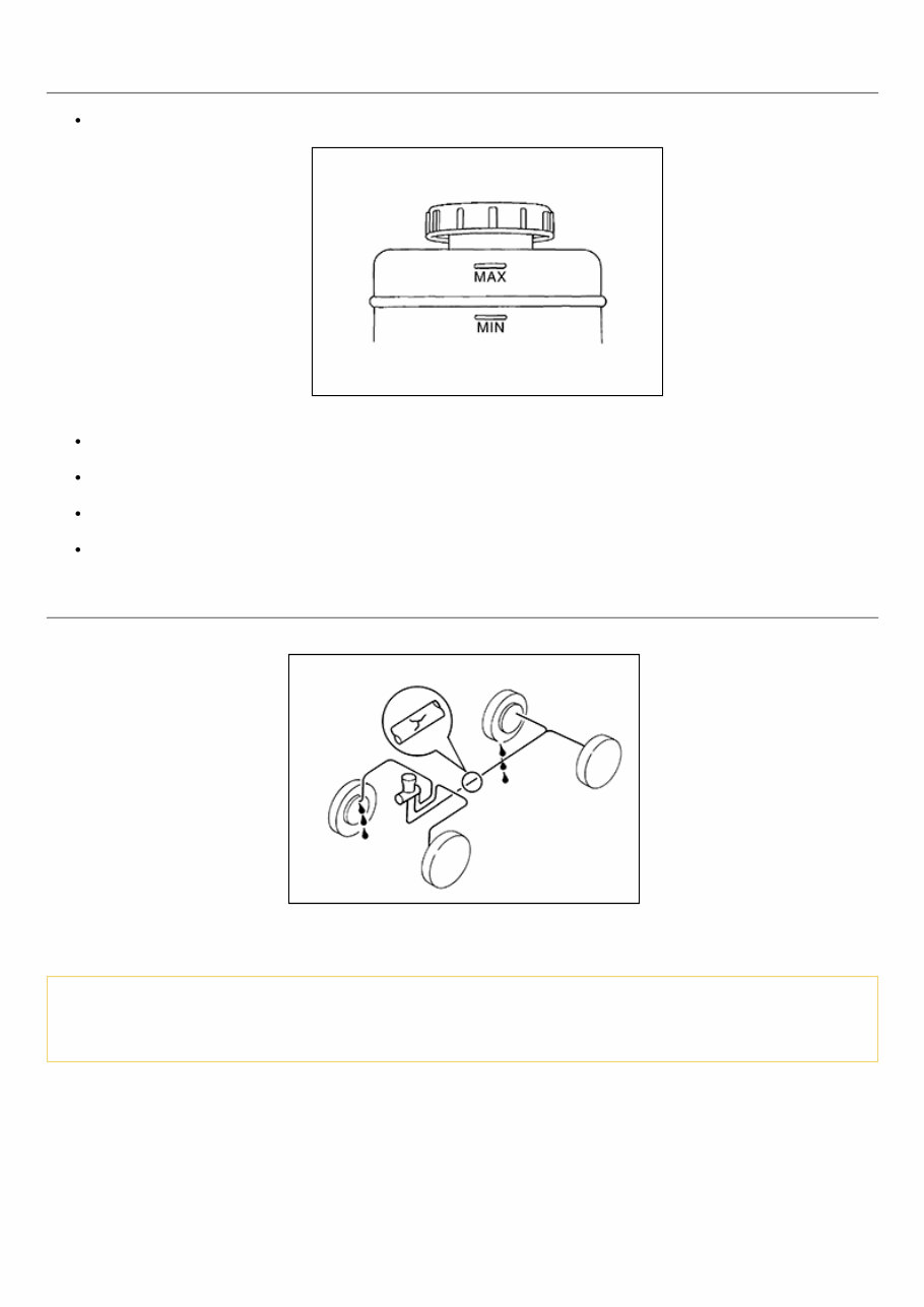
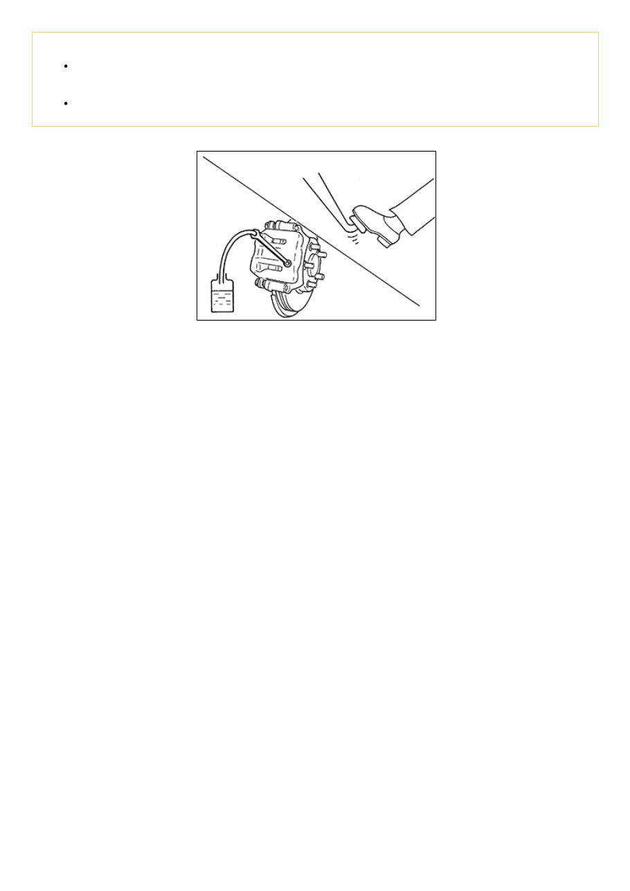
Inspection RPR-001020304 BRAKE FLUID LEVEL Check that the fluid level in the reservoir tank is within the specified range (MAX – MIN lines). RPR-001020304-01-PFIA0007ZZ Visually check for any brake fluid leakage around the reservoir tank. Check the brake system for any leakage if the fluid level is extremely low (lower than MIN). Check the brake system for fluid leakage if the warning lamp remains illuminated even after the parking brake is released. Check the reservoir tank for the mixing of foreign matter (e.g. dust) and oils other than brake fluid. BRAKE LINE 1 Check brake line (tubes and hoses) for cracks, deterioration or other damage. Replace any damaged parts. RPR-001020304-02-BR389C 2 Check for brake fluid leakage by fully depressing brake pedal while engine is running. CAUTION: Retighten the applicable connection to the specified torque and repair any abnormal (damaged, worn or deformed) part if any brake fluid leakage is present.
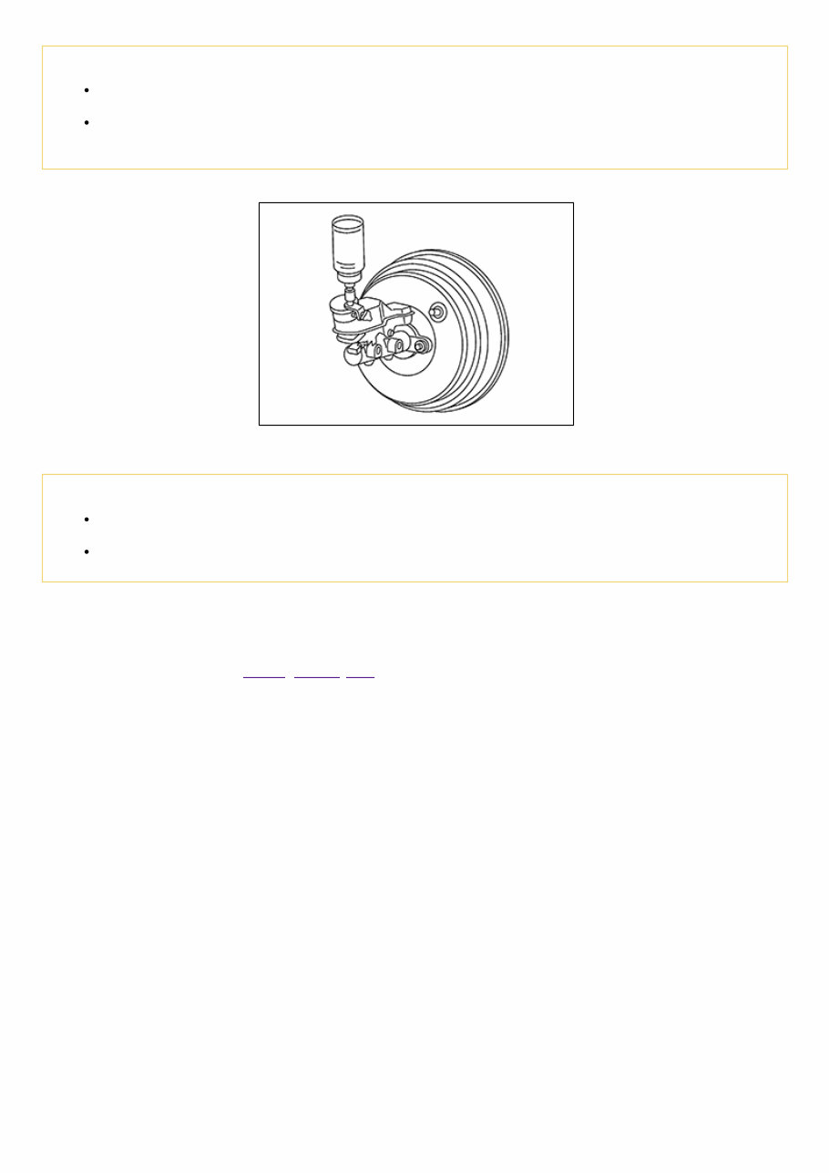
Draining CAUTION: Do not spill or splash brake fluid on painted surfaces. Brake fluid may seriously damage paint. Wipe it off immediately and wash with water if it gets on a painted surface. Turn the ignition switch OFF and battery negative terminal before performing work. 1 Connect a vinyl tube to the bleed valve. NISB0000000014660088-01-BRA0007D 2 Depress the brake pedal and loosen the bleeder valve to gradually discharge brake fluid.
Refilling RPR-001020347 CAUTION: Turn the ignition switch OFF and battery negative terminal before performing work. Do not spill or splash brake fluid on painted surfaces. Brake fluid may seriously damage paint. Wipe it off immediately and wash with water if it gets on a painted surface. 1 Check that there is no foreign material in the reservoir tank, and refill with new brake fluid. RPR-001020347-01-FIA0403J CAUTION: Do not reuse drained brake fluid. Do not allow foreign matter (e.g. dust) and oils other than brake fluid to enter the reservoir tank. 2 Loosen the bleeder valve, slowly depress the brake pedal to the full stroke, and then release the pedal. Repeat this operation at intervals of 2 or 3 seconds until new brake fluid is discharged. Then close the bleeder valve with the brake pedal depressed. Repeat the same work on each wheel. 3 Perform the air bleeding. Refer to Bleeding Brake System.
The 2019 Nissan Micra Service & Repair Manual is the ultimate tool for any vehicle owner looking to tackle repairs and maintenance on their own. With step-by-step instructions, clear images, and exploded-view illustrations, this manual provides everything you need to troubleshoot and replace any part on your Micra.
While the durability of the Micra is unquestionable, regular maintenance is still necessary for optimal performance. And when it comes to replacing worn out parts, having a good repair manual can save you time and money. With the manufacturer's recommended troubleshooting charts and replacement procedures, you'll have all the guidance you need to keep your Micra running smoothly.
One of the best things about this manual is its convenience. No need to flip through hundreds of pages to find the information you need. With the ability to carry it on any electronic device, from computers to smartphones, you'll have access to the manual whenever and wherever you need it. And if you prefer a physical copy, you can easily print it out.
Included in this manual are troubleshooting and replacement procedures provided by the manufacturer, making it the most comprehensive guide available. So why rely on a repair shop when you can have all the resources you need at your fingertips? Keep your Micra in top shape and save money on repairs with the 2019 Nissan Micra Service & Repair Manual.
Includes step-by-step instructions, clear images, and exploded-view illustrations
Compatible with any electronic device, including PC, Mac, smartphones, and tablets