
2010-2017 Nissan Micra (K13) Service & Repair Manual
What's Included?
Fast Download Speeds
Online & Offline Access
Access PDF Contents & Bookmarks
Full Search Facility
Print one or all pages of your manual

ACC-1
ENGINE
C
D
E
F
G
H
I
J
K
L
M
SECTION ACC
A
ACC
N
O
P
CONTENTS
ACCELERATOR CONTROL SYSTEM
PRECAUTION .............................................. 2
PRECAUTIONS .................................................. 2
FOR EUROPE ............................................................ 2
FOR EUROPE : Precaution for Supplemental Re-
straint System (SRS) "AIR BAG" and "SEAT BELT
PRE-TENSIONER" .................................................. 2
EXCEPT FOR EUROPE ............................................. 2
EXCEPT FOR EUROPE : Precaution for Supple-
mental Restraint System (SRS) "AIR BAG" and
"SEAT BELT PRE-TENSIONER" ............................ 2
REMOVAL AND INSTALLATION ............... 4
ACCELERATOR CONTROL SYSTEM .............. 4
Exploded View ......................................................... 4
Removal and Installation ......................................... 4
Inspection ................................................................ 4

ACC-2
< PRECAUTION >
PRECAUTIONS
PRECAUTION
PRECAUTIONS
FOR EUROPE
FOR EUROPE : Precaution for Supplemental Restraint System (SRS) "AIR BAG" and
"SEAT BELT PRE-TENSIONER" INFOID:0000000006845278
The Supplemental Restraint System such as “AIR BAG” and “SEAT BELT PRE-TENSIONER”, used along
with a front seat belt, helps to reduce the risk or severity of injury to the driver and front passenger for certain
types of collision. Information necessary to service the system safely is included in the “SRS AIR BAG” and
“SEAT BELT” of this Service Manual.
The vehicle may be equipped with a passenger air bag deactivation switch. Because no rear seat exists where
a rear-facing child restraint can be placed, the switch is designed to turn off the passenger air bag so that a
rear-facing child restraint can be used in the front passenger seat. The switch is located in the center of the
instrument panel, near the ashtray. When the switch is turned to the ON position, the passenger air bag is
enabled and could inflate for certain types of collision. When the switch is turned to the OFF position, the pas-
senger air bag is disabled and will not inflate. A passenger air bag OFF indicator on the instrument panel lights
up when the passenger air bag is switched OFF. The driver air bag always remains enabled and is not affected
by the passenger air bag deactivation switch.
WARNING:
Always observe the following items for preventing accidental activation.
• To avoid rendering the SRS inoperative, which could increase the risk of personal injury or death in
the event of a collision that would result in air bag inflation, all maintenance must be performed by
an authorized NISSAN/INFINITI dealer.
• Improper maintenance, including incorrect removal and installation of the SRS, can lead to personal
injury caused by unintentional activation of the system. For removal of Spiral Cable and Air Bag
Module, see the “SRS AIR BAG”.
• Do not use electrical test equipment on any circuit related to the SRS unless instructed to in this
Service Manual. SRS wiring harnesses can be identified by yellow and/or orange harnesses or har-
ness connectors.
• The vehicle may be equipped with a passenger air bag deactivation switch which can be operated by
the customer. When the passenger air bag is switched OFF, the passenger air bag is disabled and
will not inflate. When the passenger air bag is switched ON, the passenger air bag is enabled and
could inflate for certain types of collision. After SRS maintenance or repair, make sure the passenger
air bag deactivation switch is in the same position (ON or OFF) as when the vehicle arrived for ser-
vice.
PRECAUTIONS WHEN USING POWER TOOLS (AIR OR ELECTRIC) AND HAMMERS
WARNING:
Always observe the following items for preventing accidental activation.
• When working near the Air Bag Diagnosis Sensor Unit or other Air Bag System sensors with the
ignition ON or engine running, DO NOT use air or electric power tools or strike near the sensor(s)
with a hammer. Heavy vibration could activate the sensor(s) and deploy the air bag(s), possibly
causing serious injury.
• When using air or electric power tools or hammers, always switch the ignition OFF, disconnect the
battery, and wait at least 3 minutes before performing any service.
EXCEPT FOR EUROPE
EXCEPT FOR EUROPE : Precaution for Supplemental Restraint System (SRS) "AIR
BAG" and "SEAT BELT PRE-TENSIONER" INFOID:0000000006845279
The Supplemental Restraint System such as “AIR BAG” and “SEAT BELT PRE-TENSIONER”, used along
with a front seat belt, helps to reduce the risk or severity of injury to the driver and front passenger for certain
types of collision. Information necessary to service the system safely is included in the “SRS AIR BAG” and
“SEAT BELT” of this Service Manual.
WARNING:

PRECAUTIONS
ACC-3
< PRECAUTION >
C
D
E
F
G
H
I
J
K
L
M
A
ACC
N
P
O
Always observe the following items for preventing accidental activation.
• To avoid rendering the SRS inoperative, which could increase the risk of personal injury or death in
the event of a collision that would result in air bag inflation, all maintenance must be performed by
an authorized NISSAN/INFINITI dealer.
• Improper maintenance, including incorrect removal and installation of the SRS, can lead to personal
injury caused by unintentional activation of the system. For removal of Spiral Cable and Air Bag
Module, see “SRS AIR BAG”.
• Never use electrical test equipment on any circuit related to the SRS unless instructed to in this Ser-
vice Manual. SRS wiring harnesses can be identified by yellow and/or orange harnesses or harness
connectors.
PRECAUTIONS WHEN USING POWER TOOLS (AIR OR ELECTRIC) AND HAMMERS
WARNING:
Always observe the following items for preventing accidental activation.
• When working near the Air Bag Diagnosis Sensor Unit or other Air Bag System sensors with the
ignition ON or engine running, never use air or electric power tools or strike near the sensor(s) with
a hammer. Heavy vibration could activate the sensor(s) and deploy the air bag(s), possibly causing
serious injury.
• When using air or electric power tools or hammers, always switch the ignition OFF, disconnect the
battery, and wait at least 3 minutes before performing any service.
ACC-4
< REMOVAL AND INSTALLATION >
ACCELERATOR CONTROL SYSTEM
REMOVAL AND INSTALLATION
ACCELERATOR CONTROL SYSTEM
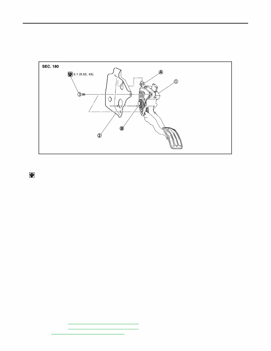
Exploded View INFOID:0000000005988502
Removal and Installation INFOID:0000000005988503
REMOVAL
1. Disconnect accelerator pedal position sensor harness connector.
2. Loosen mounting bolts, and remove accelerator pedal assembly.
CAUTION:
• Never disassemble accelerator pedal assembly. Never remove accelerator pedal position sensor
from accelerator pedal assembly.
• Avoid impact from dropping etc. during handling.
• Be careful to keep accelerator pedal assembly away from water.
INSTALLATION
Note the following, and install in the reverse order of removal.
• Insert the locating pin while inserting the locating hook in to the break pedal bracket. Tighten mounting bolts
to accelerator pedal assembly.
CAUTION:
Never squeeze the locating hook into the break pedal bracket when inserting the locating pin into the
hole on the brake pedal bracket side.
Inspection INFOID:0000000005988504
INSPECTION AFTER INSTALLATION
• Check accelerator pedal moves smoothly within the whole operation range when it is fully depressed and
released.
• Check accelerator pedal securely returns to the fully released position.
• For the electrical inspection of accelerator pedal position sensor. Refer to following;
- HR12DE (TYPE 1): EC3-407, " Component Inspection "
- HR12DE (TYPE 2): EC3-747, " Component Inspection "
- HR12DDR: EC3-1297, " Component Inspection "
1. Accelerator pedal assembly 2. Brake pedal bracket
A. Locating hook B. Locating pin
: N·m (kg-m, in-lb)
JPBIA3364GB

ACCELERATOR CONTROL SYSTEM
ACC-5
< REMOVAL AND INSTALLATION >
C
D
E
F
G
H
I
J
K
L
M
A
ACC
N
P
O
- HR15DE (TYPE 1): EC4-279, " Component Inspection "
- HR15DE (TYPE 2): EC4-497, " Component Inspection "
- K9K: ECD-175, " Component Inspection "
CAUTION:
When harness connector of accelerator pedal position sensor is disconnected, perform “ACCELERA-
TOR PEDAL RELEASED POSITION LEARNING”. Refer to following;
• HR12DE (TYPE 1): EC3-171, " Work Procedure "
• HR12DE (TYPE 2): EC3-594, " Work Procedure "
• HR12DDR: EC3-999, " Work Procedure "
• HR15DE (TYPE 1): EC4-108, " Work Procedure "
• HR15DE (TYPE 2): EC4-392, " Work Procedure "

SRC-1
RESTRAINTS
C
D
E
F
G
I
J
K
L
M
SECTION SRC
A
B
SRC
N
O
P
CONTENTS
SRS AIRBAG CONTROL SYSTEM
TYPE 1
HOW TO USE THIS MANUAL ..................... 6
APPLICATION NOTICE ..................................... 6
Information ............................................................... 6
PRECAUTION .............................................. 7
PRECAUTIONS .................................................. 7
Precaution for Supplemental Restraint System
(SRS) "AIR BAG" and "SEAT BELT PRE-TEN-
SIONER" .................................................................. 7
Service ..................................................................... 7
SYSTEM DESCRIPTION ............................. 8
COMPONENT PARTS ....................................... 8
Component Parts Location ....................................... 8
Component Description ............................................ 9
SYSTEM ............................................................10
System Diagram ..................................................... 10
System Description ................................................ 11
DIAGNOSIS SYSTEM (AIR BAG) ....................13
Description ............................................................. 13
On Board Diagnosis Function ................................ 13
CONSULT Function ............................................... 16
ECU DIAGNOSIS INFORMATION ............. 17
DIAGNOSIS SENSOR UNIT .............................17
DTC Index ............................................................. 17
WIRING DIAGRAM ..................................... 19
SRS AIR BAG SYSTEM ....................................19
Application Notice .................................................. 19
TYPE A ..................................................................... 19
TYPE A : Wiring Diagram ....................................... 20
TYPE B ......................................................................23
TYPE B : Wiring Diagram .......................................24
BASIC INSPECTION .................................. 26
DIAGNOSIS AND REPAIR WORK FLOW ....... 26
Work Flow ...............................................................26
DTC/CIRCUIT DIAGNOSIS ........................ 29
B1001, B1002, B1003, B1004, B1005 DIAG-
NOSIS SENSOR UNIT ...................................... 29
DTC Logic ...............................................................29
Diagnosis Procedure ..............................................29
B1006, B1007, B1008, B1009, B1010 DIAG-
NOSIS SENSOR UNIT ...................................... 30
DTC Logic ...............................................................30
Diagnosis Procedure ..............................................30
B1011, B1012, B1013, B1014, B1015 DIAG-
NOSIS SENSOR UNIT ...................................... 31
DTC Logic ...............................................................31
Diagnosis Procedure ..............................................31
B1033, B1034 CRASH ZONE SENSOR ........... 32
DTC Logic ...............................................................32
Diagnosis Procedure ..............................................32
B1035 CRASH ZONE SENSOR ....................... 34
DTC Logic ...............................................................34
Diagnosis Procedure ..............................................34
B1042, B1043, B1044, B1045, B1046, B1047
DIAGNOSIS SENSOR UNIT ............................. 36
DTC Logic ...............................................................36
Diagnosis Procedure ..............................................36
B1049 DRIVER AIRBAG MODULE .................. 37
DTC Logic ...............................................................37
Diagnosis Procedure ..............................................37
B1050 DRIVER AIRBAG MODULE .................. 39

SRC-2
DTC Logic .............................................................. 39
Diagnosis Procedure ............................................. 39
B1051 DRIVER AIRBAG MODULE ................. 41
DTC Logic .............................................................. 41
Diagnosis Procedure ............................................. 41
B1052 DRIVER AIRBAG MODULE ................. 43
DTC Logic .............................................................. 43
Diagnosis Procedure ............................................. 43
B1058, B1059 DIAGNOSIS SENSOR UNIT .... 45
Description ............................................................. 45
DTC Logic .............................................................. 45
Diagnosis Procedure ............................................. 45
B1065 PASSENGER AIR BAG MODULE ....... 46
DTC Logic .............................................................. 46
Diagnosis Procedure ............................................. 46
B1066 PASSENGER AIR BAG MODULE ....... 48
DTC Logic .............................................................. 48
Diagnosis Procedure ............................................. 48
B1067 PASSENGER AIR BAG MODULE ....... 50
DTC Logic .............................................................. 50
Diagnosis Procedure ............................................. 50
B1068 PASSENGER AIR BAG MODULE ....... 52
DTC Logic .............................................................. 52
Diagnosis Procedure ............................................. 52
B1074, B1075 DIAGNOSIS SENSOR INIT ...... 54
DTC Logic .............................................................. 54
Diagnosis Procedure ............................................. 54
B1081 SEAT BELT PRE-TENSIONER RH ...... 55
DTC Logic .............................................................. 55
Diagnosis Procedure ............................................. 55
B1082 SEAT BELT PRE-TENSIONER RH ...... 57
DTC Logic .............................................................. 57
Diagnosis Procedure ............................................. 57
B1083 SEAT BELT PRE-TENSIONER RH ...... 59
DTC Logic .............................................................. 59
Diagnosis Procedure ............................................. 59
B1084 SEAT BELT PRE-TENSIONER RH ...... 61
DTC Logic .............................................................. 61
Diagnosis Procedure ............................................. 61
B1086 SEAT BELT PRE-TENSIONER LH ...... 63
DTC Logic .............................................................. 63
Diagnosis Procedure ............................................. 63
B1087 SEAT BELT PRE-TENSIONER LH ...... 65
DTC Logic .............................................................. 65
Diagnosis Procedure ............................................. 65
B1088 SEAT BELT PRE-TENSIONER LH ...... 67
DTC Logic .............................................................. 67
Diagnosis Procedure .............................................. 67
B1089 SEAT BELT PRE-TENSIONER LH ...... 69
DTC Logic .............................................................. 69
Diagnosis Procedure .............................................. 69
B1090, B1091, B1092, B1093 DIAGNOSIS
SENSOR UNIT .................................................. 71
DTC Logic .............................................................. 71
Diagnosis Procedure .............................................. 71
B1209 FRONTAL COLLISION DETECTION ... 72
Description ............................................................. 72
DTC Logic .............................................................. 72
Diagnosis Procedure .............................................. 72
SYMPTOM DIAGNOSIS ............................ 73
SRS AIR BAG WARNING LAMP DOES NOT
TURN OFF ........................................................ 73
Diagnosis Procedure .............................................. 73
SRS AIR BAG WARNING LAMP DOES NOT
TURN ON .......................................................... 74
Diagnosis Procedure .............................................. 74
TYPE 2
HOW TO USE THIS MANUAL ................... 75
APPLICATION NOTICE ................................... 75
Information ............................................................. 75
PRECAUTION ............................................ 76
PRECAUTIONS ................................................ 76
FOR EUROPE .......................................................... 76
FOR EUROPE : Precaution for Supplemental Re-
straint System (SRS) "AIR BAG" and "SEAT BELT
PRE-TENSIONER" ................................................ 76
FOR EUROPE : Service ........................................ 76
EXCEPT FOR EUROPE ........................................... 77
EXCEPT FOR EUROPE : Precaution for Supple-
mental Restraint System (SRS) "AIR BAG" and
"SEAT BELT PRE-TENSIONER" .......................... 77
EXCEPT FOR EUROPE : Service ......................... 78
SYSTEM DESCRIPTION ........................... 79
COMPONENT PARTS ...................................... 79
Component Parts Location .................................... 79
Component Description ......................................... 80
SYSTEM ........................................................... 81
System Diagram .................................................... 81
System Description ................................................ 81
DIAGNOSIS SYSTEM (AIR BAG) .................... 83
Description ............................................................. 83
On Board Diagnosis Function ................................ 83
CONSULT Function ............................................... 86

SRC-3
C
D
E
F
G
I
J
K
L
M
A
B
SRC
N
O
P
ECU DIAGNOSIS INFORMATION ............. 88
DIAGNOSIS SENSOR UNIT .............................88
DTC Index ............................................................. 88
WIRING DIAGRAM ..................................... 91
SRS AIR BAG SYSTEM ....................................91
Application Notice .................................................. 91
TYPE A ..................................................................... 91
TYPE A : Wiring Diagram ....................................... 92
TYPE B ..................................................................... 97
TYPE B : Wiring Diagram ....................................... 98
TYPE C ................................................................... 102
TYPE C : Wiring Diagram .................................... 103
BASIC INSPECTION ................................ 105
DIAGNOSIS AND REPAIR WORK FLOW ..... 105
Work Flow ............................................................ 105
DTC/CIRCUIT DIAGNOSIS ...................... 108
B1001, B1002, B1003, B1004, B1005 DIAG-
NOSIS SENSOR UNIT .................................... 108
DTC Logic ............................................................ 108
Diagnosis Procedure ............................................ 108
B1006, B1007, B1008, B1009, B1010 DIAG-
NOSIS SENSOR UNIT .................................... 109
DTC Logic ............................................................ 109
Diagnosis Procedure ............................................ 109
B1011, B1012, B1013, B1014, B1015 DIAG-
NOSIS SENSOR UNIT .................................... 110
DTC Logic ............................................................ 110
Diagnosis Procedure ............................................ 110
B1023 PASSENGER AIR BAG OFF INDICA-
TOR ................................................................. 111
DTC Logic ............................................................ 111
Diagnosis Procedure ............................................ 111
B1024 PASS A/B DEACT SW ........................ 113
DTC Logic ............................................................ 113
Diagnosis Procedure ............................................ 113
B1033, B1034 CRASH ZONE SENSOR ......... 115
DTC Logic ............................................................ 115
Diagnosis Procedure ............................................ 115
B1035 CRASH ZONE SENSOR ..................... 117
DTC Logic ............................................................ 117
Diagnosis Procedure ............................................ 117
B1042, B1043, B1044, B1045, B1046, B1047
DIAGNOSIS SENSOR UNIT ........................... 119
DTC Logic ............................................................ 119
Diagnosis Procedure ............................................ 119
B1049 DRIVER AIRBAG MODULE ................ 120
DTC Logic ............................................................. 120
Diagnosis Procedure ............................................ 120
B1050 DRIVER AIRBAG MODULE ................ 122
DTC Logic ............................................................. 122
Diagnosis Procedure ............................................ 122
B1051 DRIVER AIRBAG MODULE ................ 124
DTC Logic ............................................................. 124
Diagnosis Procedure ............................................ 124
B1052 DRIVER AIRBAG MODULE ................ 126
DTC Logic ............................................................. 126
Diagnosis Procedure ............................................ 126
B1058, B1059 DIAGNOSIS SENSOR UNIT ... 128
DTC Logic ............................................................. 128
Diagnosis Procedure ............................................ 128
B1065 PASSENGER AIR BAG MODULE ...... 129
DTC Logic ............................................................. 129
Diagnosis Procedure ............................................ 129
B1066 PASSENGER AIR BAG MODULE ...... 131
DTC Logic ............................................................. 131
Diagnosis Procedure ............................................ 131
B1067 PASSENGER AIR BAG MODULE ...... 133
DTC Logic ............................................................. 133
Diagnosis Procedure ............................................ 133
B1068 PASSENGER AIR BAG MODULE ...... 135
DTC Logic ............................................................. 135
Diagnosis Procedure ............................................ 135
B1074, B1075 DIAGNOSIS SENSOR INIT .... 137
DTC Logic ............................................................. 137
Diagnosis Procedure ............................................ 137
B1081 SEAT BELT PRE-TENSIONER RH .... 138
DTC Logic ............................................................. 138
Diagnosis Procedure ............................................ 138
B1082 SEAT BELT PRE-TENSIONER RH .... 140
DTC Logic ............................................................. 140
Diagnosis Procedure ............................................ 140
B1083 SEAT BELT PRE-TENSIONER RH .... 142
DTC Logic ............................................................. 142
Diagnosis Procedure ............................................ 142
B1084 SEAT BELT PRE-TENSIONER RH .... 144
DTC Logic ............................................................. 144
Diagnosis Procedure ............................................ 144
B1086 SEAT BELT PRE-TENSIONER LH ..... 146
DTC Logic ............................................................. 146
Diagnosis Procedure ............................................ 146
B1087 SEAT BELT PRE-TENSIONER LH ..... 148
DTC Logic ............................................................. 148

SRC-4
Diagnosis Procedure ............................................ 148
B1088 SEAT BELT PRE-TENSIONER LH .... 150
DTC Logic ............................................................. 150
Diagnosis Procedure ............................................ 150
B1089 SEAT BELT PRE-TENSIONER LH .... 152
DTC Logic ............................................................. 152
Diagnosis Procedure ............................................ 152
B1090, B1091, B1092, B1093 DIAGNOSIS
SENSOR UNIT ................................................ 154
DTC Logic ............................................................. 154
Diagnosis Procedure ............................................ 154
B1113, B1114 SATELLITE SENSOR RH ...... 155
DTC Logic ............................................................. 155
Diagnosis Procedure ............................................ 155
B1115 SATELLITE SENSOR RH ................... 157
DTC Logic ............................................................. 157
Diagnosis Procedure ............................................ 157
B1118, B1119 SATELLITE SENSOR LH ....... 159
DTC Logic ............................................................. 159
Diagnosis Procedure ............................................ 159
B1120 SATELLITE SENSOR LH ................... 161
DTC Logic ............................................................. 161
Diagnosis Procedure ............................................ 161
B1122, B1123, B1124, B1125 DIAGNOSIS
SENSOR UNIT ................................................ 163
DTC Logic ............................................................. 163
Diagnosis Procedure ............................................ 163
B1129 SIDE AIR BAG MODULE RH ............. 164
DTC Logic ............................................................. 164
Diagnosis Procedure ............................................ 164
B1130 SIDE AIR BAG MODULE RH ............. 166
DTC Logic ............................................................. 166
Diagnosis Procedure ............................................ 166
B1131 SIDE AIR BAG MODULE RH ............. 168
DTC Logic ............................................................. 168
Diagnosis Procedure ............................................ 168
B1132 SIDE AIR BAG MODULE RH ............. 170
DTC Logic ............................................................. 170
Diagnosis Procedure ............................................ 170
B1134 SIDE AIR BAG MODULE LH .............. 172
DTC Logic ............................................................. 172
Diagnosis Procedure ............................................ 172
B1135 SIDE AIR BAG MODULE LH .............. 174
DTC Logic ............................................................. 174
Diagnosis Procedure ............................................ 174
B1136 SIDE AIR BAG MODULE LH .............. 176
DTC Logic ............................................................. 176
Diagnosis Procedure ............................................ 176
B1137 SIDE AIR BAG MODULE LH ............... 178
DTC Logic ............................................................ 178
Diagnosis Procedure ............................................ 178
B1138, B1139, B1140, B1141 DIAGNOSIS
SENSOR INIT .................................................. 180
DTC Logic ............................................................ 180
Diagnosis Procedure ............................................ 180
B1145 CURTAIN AIR BAG MODULE RH ...... 181
DTC Logic ............................................................ 181
Diagnosis Procedure ............................................ 181
B1146 CURTAIN AIR BAG MODULE RH ...... 183
DTC Logic ............................................................ 183
Diagnosis Procedure ............................................ 183
B1147 CURTAIN AIR BAG MODULE RH ...... 185
DTC Logic ............................................................ 185
Diagnosis Procedure ............................................ 185
B1148 CURTAIN AIR BAG MODULE RH ...... 187
DTC Logic ............................................................ 187
Diagnosis Procedure ............................................ 187
B1150 CURTAIN AIR BAG MODULE LH ....... 189
DTC Logic ............................................................ 189
Diagnosis Procedure ............................................ 189
B1151 CURTAIN AIR BAG MODULE LH ....... 191
DTC Logic ............................................................ 191
Diagnosis Procedure ............................................ 191
B1152 CURTAIN AIR BAG MODULE LH ....... 193
DTC Logic ............................................................ 193
Diagnosis Procedure ............................................ 193
B1153 CURTAIN AIR BAG MODULE LH ....... 195
DTC Logic ............................................................ 195
Diagnosis Procedure ............................................ 195
B1154, B1155, B1156, B1157 DIAGNOSIS
SENSOR UNIT ................................................. 197
DTC Logic ............................................................ 197
Diagnosis Procedure ............................................ 197
B1209 FRONTAL COLLISION DETECTION .. 198
Description ........................................................... 198
DTC Logic ............................................................ 198
Diagnosis Procedure ............................................ 198
B1210 SIDE COLLISION DETECTION ........... 199
Description ........................................................... 199
DTC Logic ............................................................ 199
Diagnosis Procedure ............................................ 199
SYMPTOM DIAGNOSIS ........................... 200
SRS AIR BAG WARNING LAMP DOES NOT
TURN OFF ....................................................... 200

SRC-5
C
D
E
F
G
I
J
K
L
M
A
B
SRC
N
O
P
Diagnosis Procedure ............................................ 200 SRS AIR BAG WARNING LAMP DOES NOT
TURN ON ........................................................ 201
Diagnosis Procedure ............................................ 201
You're Reading a Preview
What's Included?
Fast Download Speeds
Online & Offline Access
Access PDF Contents & Bookmarks
Full Search Facility
Print one or all pages of your manual
$29.99
$38.99
Viewed 18 Times Today


Secure transaction
What's Included?
Fast Download Speeds
Online & Offline Access
Access PDF Contents & Bookmarks
Full Search Facility
Print one or all pages of your manual
$29.99
$38.99
The 2010 - 2017 Nissan Micra (K13) Service & Repair Manual is an essential resource for any Micra owner looking to maintain, repair, or service their vehicle. This comprehensive guide is available in PDF format, making it accessible on a range of devices.
Key Features:
- Detailed repair instructions for a variety of issues
- Step-by-step maintenance procedures
- High-quality diagrams and illustrations for clear understanding
- Troubleshooting guides to help diagnose and resolve problems quickly
- Electrical wiring diagrams
Engines Covered:
- 1.2 Petrol HR12DE
- 1.5 Petrol HR15DE
- 1.2 Petrol HR12DDR (DIG-S)
- 1.5 Diesel K9K
Whether you are a professional mechanic or a Nissan Micra owner, this manual provides all the essential information needed to service and repair your vehicle effectively. With easy-to-follow instructions and comprehensive coverage of the K13 model's features, it is a valuable tool for ensuring your Nissan Micra remains in excellent condition.
Download your copy today and keep your Nissan Micra performing at its best!


