ACC-1 ENGINE C D E F G H I J K L M SECTION ACC A ACC N O P CONTENTS ACCELERATOR CONTROL SYSTEM PRECAUTION .............................................. 2 PRECAUTIONS .................................................. 2 Precaution for Supplemental Restraint System (SRS) "AIR BAG" and "SEAT BELT PRE-TEN- SIONER" .................................................................. 2 REMOVAL AND INSTALLATION ............... 3 ACCELERATOR CONTROL SYSTEM .............. 3 Exploded View ......................................................... 3 Removal and Installation ......................................... 3 Inspection ................................................................ 3
ACC-2 < PRECAUTION > PRECAUTIONS PRECAUTION PRECAUTIONS Precaution for Supplemental Restraint System (SRS) "AIR BAG" and "SEAT BELT PRE-TENSIONER" INFOID:0000000006752514 The Supplemental Restraint System such as “AIR BAG” and “SEAT BELT PRE-TENSIONER”, used along with a front seat belt, helps to reduce the risk or severity of injury to the driver and front passenger for certain types of collision. Information necessary to service the system safely is included in the “SRS AIR BAG” and “SEAT BELT” of this Service Manual. The vehicle may be equipped with a passenger air bag deactivation switch. Because no rear seat exists where a rear-facing child restraint can be placed, the switch is designed to turn off the passenger air bag so that a rear-facing child restraint can be used in the front passenger seat. The switch is located in the center of the instrument panel, near the ashtray. When the switch is turned to the ON position, the passenger air bag is enabled and could inflate for certain types of collision. When the switch is turned to the OFF position, the pas- senger air bag is disabled and will not inflate. A passenger air bag OFF indicator on the instrument panel lights up when the passenger air bag is switched OFF. The driver air bag always remains enabled and is not affected by the passenger air bag deactivation switch. WARNING: • To avoid rendering the SRS inoperative, which could increase the risk of personal injury or death in the event of a collision which would result in air bag inflation, all maintenance must be performed by an authorized NISSAN/INFINITI dealer. • Improper maintenance, including incorrect removal and installation of the SRS, can lead to personal injury caused by unintentional activation of the system. For removal of Spiral Cable and Air Bag Module, see the “SRS AIR BAG”. • Do not use electrical test equipment on any circuit related to the SRS unless instructed to in this Service Manual. SRS wiring harnesses can be identified by yellow and/or orange harnesses or har- ness connectors. • The vehicle may be equipped with a passenger air bag deactivation switch which can be operated by the customer. When the passenger air bag is switched OFF, the passenger air bag is disabled and will not inflate. When the passenger air bag is switched ON, the passenger air bag is enabled and could inflate for certain types of collision. After SRS maintenance or repair, make sure the passenger air bag deactivation switch is in the same position (ON or OFF) as when the vehicle arrived for ser- vice. PRECAUTIONS WHEN USING POWER TOOLS (AIR OR ELECTRIC) AND HAMMERS WARNING: • When working near the Air Bag Diagnosis Sensor Unit or other Air Bag System sensors with the ignition ON or engine running, DO NOT use air or electric power tools or strike near the sensor(s) with a hammer. Heavy vibration could activate the sensor(s) and deploy the air bag(s), possibly causing serious injury. • When using air or electric power tools or hammers, always switch the ignition OFF, disconnect the battery, and wait at least 3 minutes before performing any service.
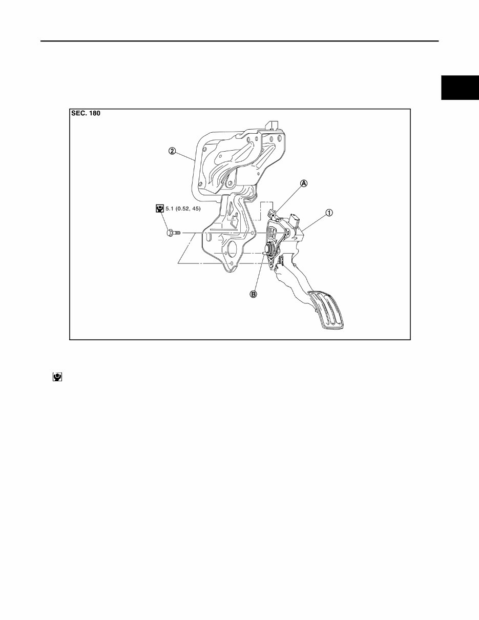
ACCELERATOR CONTROL SYSTEM ACC-3 < REMOVAL AND INSTALLATION > C D E F G H I J K L M A ACC N P O REMOVAL AND INSTALLATION ACCELERATOR CONTROL SYSTEM Exploded View INFOID:0000000006405536 Removal and Installation INFOID:0000000006405537 REMOVAL 1. Disconnect accelerator pedal position sensor harness connector. 2. Loosen mounting bolts, and remove accelerator pedal assembly. CAUTION: • Never disassemble accelerator pedal assembly. Never remove accelerator pedal position sensor from accelerator pedal assembly. • Avoid impact from dropping etc. during handling. • Be careful to keep accelerator pedal assembly away from water. INSTALLATION Note the following, and install in the reverse order of removal. • Insert the locating pin while inserting the locating hook in to the break pedal bracket. Tighten mounting bolts to accelerator pedal assembly. CAUTION: Never squeeze the locating hook into the break pedal bracket when inserting the locating pin into the hole on the brake pedal bracket side. Inspection INFOID:0000000006405538 INSPECTION AFTER INSTALLATION 1. Accelerator pedal assembly 2. Brake pedal bracket A. Locating hook B. Locating pin : N·m (kg-m, in-lb) JPBIA4114GB
ACC-4 < REMOVAL AND INSTALLATION > ACCELERATOR CONTROL SYSTEM • Check accelerator pedal moves smoothly within the whole operation range when it is fully depressed and released. • Check accelerator pedal securely returns to the fully released position. • For the electrical inspection of accelerator pedal position sensor. Refer to following; - MR16DDT: EC-387, " Component Inspection " - HR16DE: EC-749, " Component Inspection " - K9K: EC-1001, " Component Inspection " CAUTION: When harness connector of accelerator pedal position sensor is disconnected, perform “ACCELERA- TOR PEDAL RELEASED POSITION LEARNING”. Refer to following; • MR16DDT: EC-129, " Work Procedure " • HR15DE: EC-547, " Work Procedure " • K9K: EC-925, " DTC Logic "
The 2011 Nissan Juke Service & Repair Manual is a comprehensive guide for maintaining and fixing your Nissan Juke. This manual covers all aspects of the vehicle, providing detailed instructions and diagrams to ensure you can perform any necessary repairs or services.
Designed specifically for the 2011 Nissan Juke, this manual is compatible with the following models:
2011 Nissan Juke S
2011 Nissan Juke SV
2011 Nissan Juke SL
Whether you are a professional mechanic or a DIY enthusiast, this manual will help you save time and money by providing step-by-step procedures for every repair and service task. From routine maintenance to complex engine repairs, you can trust this manual to provide accurate and reliable information.
With the 2011 Nissan Juke Service & Repair Manual, you will have the knowledge and confidence to tackle any issue that may arise with your vehicle. Don't rely on expensive repair shops – empower yourself with this comprehensive manual and take control of your Nissan Juke's maintenance and repairs.