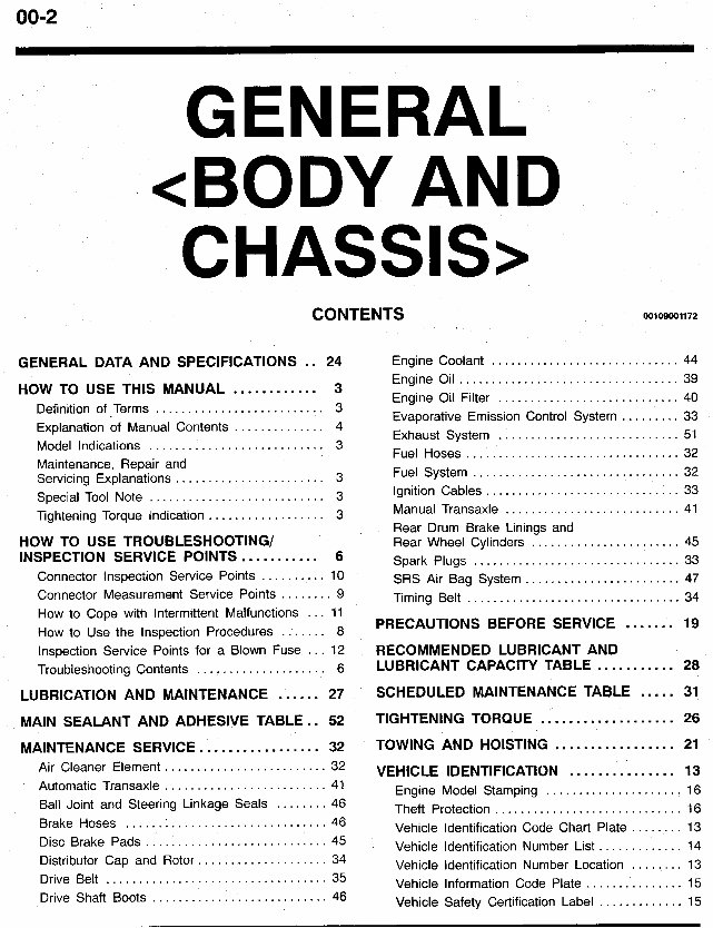
00-2 GENERAL <BODY AND CHASSIS> CONTENTS M)109001172 GENERAL DATA AND SPECIFICATIONS .. 24 Engine Coolant ............................. 44 HOW TO USE THIS MANUAL ............ 3 Definition of Terms .......................... 3 Explanation of Manual Contents .............. 4 Model Indications ........................... 3 Maintenance. Repair and Servicing Explanations ....................... 3 Tightening Torque Indication .................. 3 HOW TO USE TROUBLESHOOTING/ INSPECTION SERVICE POINTS ........... 6 Connector Inspection Service Points .......... 10 Connector Measurement Service Points ........ 9 Special Tool Note ........................... 3 Engine Oil .................................. 39 Engine Oil Filter ............................ 40 Evaporative Emission Control System ......... 33 Exhaust System ............................ 51 Fuel Hoses ................................. 32 Fuel System ................................ 32 Ignition Cables .............................. 33 Manual Transaxle ........................... 41 Rear Drum Brake Linings and Rear Wheel Cylinders ....................... 45 SRS Air Bag System ........................ 47 Timing Belt ................................. 34 Spark Plugs ................................ 33 How to Cope with Intermittent Malfunctions ... 11 How to Use the Inspection Procedures ....... 8 PRECAUTIONS BEFORE SERVICE ....... 19 Inspection Service Points for a Blown Fuse ... 12 RECOMMENDED LUBRICANT AND Troubleshooting Contents .................... 6 LUBRICANT CAPACITY TABLE ........... 28 LUBRICATION AND MAINTENANCE ...... 27 SCHEDULED MAINTENANCE TABLE ..... 31 MAINTENANCE SERVICE ................. 32 TOWING AND HOISTING ................. 21 MAIN SEALANT AND ADHESIVE TABLE .. 52 TIGHTENING TORQUE ................... 26 Air Cleaner Element ......................... 32 Automatic Transaxle ......................... 41 Ball Joint and Steering Linkage Seals ........ 46 Brake Hoses ............................... 46 Disc Brake Pads ............................ 45 Distributor Cap and Rotor .................... 34 Drive Belt .................................. 35 Drive Shaft Boots ........................... 46 VEHICLE IDENTIFICATION ............... 13 Engine Model Stamping ..................... 16 Theft Protection ............................. 16 Vehicle Identification Code Chart Plate ........ 13 Vehicle Identification Number List ............. 14 Vehicle Identification Number Location ........ 13 Vehicle Information Code Plate ............... 15 Vehicle Safety Certification Label ............. 15
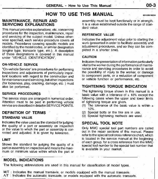
GENERAL - How to Use This Manual 00-3 MAINTENANCE, REPAIR AND SERVlC I NG EXPLAN AT1 0 N S This manual providesexplanations,etc. concerning procedures for the inspection, maintenance,repair and servicing of the subject model. Unless other- wise specified, each service procedure covers all models. Procedures covering specific models are identified by the modelcodes, or similar designation (engine type, transaxle type, etc.). A description of these designations is covered in this manual under “VE H I C LE I DENT I F I CAT I 0 N ” . ON-VEHICLE SERVICE “On-vehicle Service” are proceduresfor performing inspections and adjustments of particularly impor- tant locations with regard to the construction and for maintenance and servicing, but other inspections (for looseness, play, cracking, damage, etc. ) must also be performed. SERVICE PROCEDURES The service steps are arranged in numericalorder. Attention must to be paid in performing vehicle serviceare describedin detail in SERVICE POINTS. DEFINITION OF TERMS STANDARD VALUE Indicatesthe value usedas the standardfor judging the quality of a part or assembly on inspection or the value to which the part or assembly is cor- rected and adjusted. It is given by tolerance. LIMIT Shows the standard for judging the quality of a part or assemblyon inspectionand meansthe maxi- mum or minimum value within which the part or HOW TO USE THIS MANUAL 001 0001 0234 assembly must be kept functionally or in strength. It is a value established outside the range of stan- dard value. REFERENCE VALUE Indicates the adjustment value prior to starting the work (presentedin order to facilitate assembly and adjustment procedures, and so they can be com- pleted in a shorter time). CAUTION Indicates the presentation of information particularly vital to the worker duringthe performance of mainte- nance and servicing procedures in order to avoid the possibility of injury to the worker, or damage to component parts, or a reduction of component or vehicle function or performance, etc. TIGHTENING TORQUE INDICATION The tightening torque shown in this manual is a basic value with a tolerance of -c 10% except the following cases when the upper and lower limits of tightening torque are given. (1) The tolerance of the basic value is within f 10%. (2) Special bolts or the like are in use. (3) Special tightening methods are used. SPECIAL TOOL NOTE Only MMC special tool part numbers are called out in the repair sections of this manual. Please refer to the special tool cross referencechart, which is located in the service manual at the beginning of each group, for a cross referencefrom the MMC special tool number to the special tool number that is available in your market. M 0 D EL INDlCATlONS The following abbreviations are used in this manual for classification of model types. M/T : Indicates the manual transaxle, or models equipped with the manual transaxle. Indicates the automatic transaxle, or models equipped with the automatic transaxle. -_____
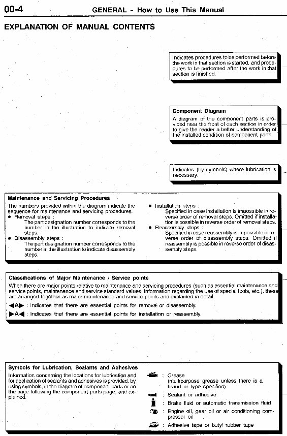
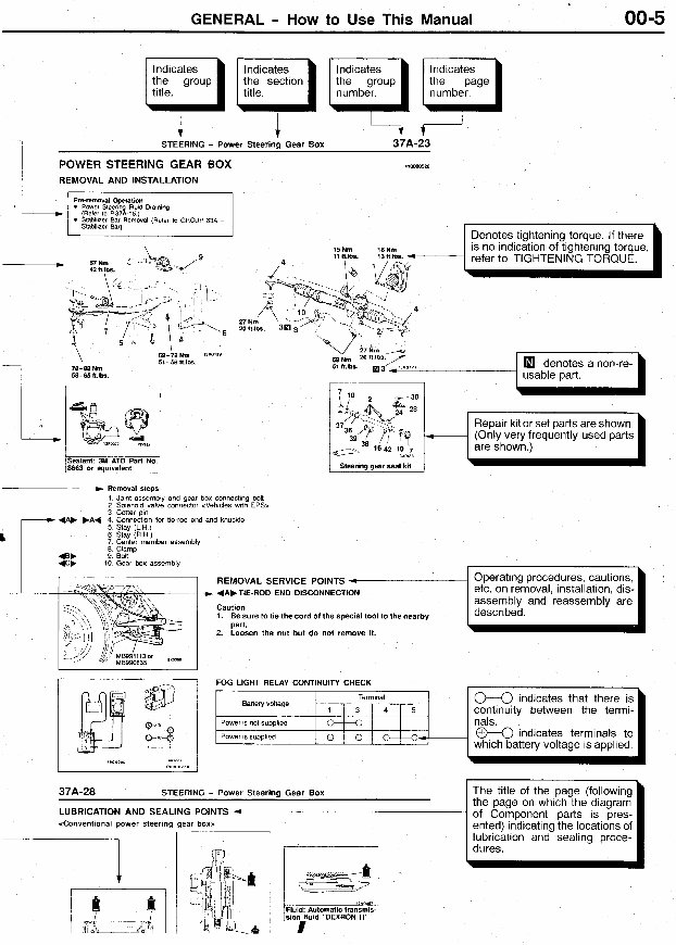
00-4 GENERAL - How to Use This Manual EXPLANATION OF MANUAL CONTENTS Maintenance and Servicing Procedures The numbers provided within the diagram indicate the sequence for maintenance and servicing procedures. 0 Removal steps . The part designation number corresponds to the number in the illustration to indicate removal 0 steps The part designation number corresponds to the number in the illustration to indicate disassembly steps. 0 0 Disassembly steps : the work in that section is started, and proce- section is finished. A diagram of the component parts is pro- to give the reader a better understanding of the installed condition of component parts. necessary. I Installation steps : Specified in case installation is impossible in re- verse order of removal steps Omitted if installa- tion is possible in reverse order of removal steps Specified in case reassembly is impossible in re- verse order of disassembly steps Omitted if reassembly is possible in reverse order of disas- sembly steps Reassembly steps Classifications of Major Maintenance / Service points When there are major points relative to maintenance and servicing procedures (such as essential maintenance and service points, maintenance and service standard values, information regarding the use of special tools, etc ), these are arranged together as major maintenance and service points and explained in detail 4Ab ' Indicates that there are essential points for removal or disassembly. FA4 : Indicates that there are essential points for installation or reassembly. - Symbols for Lubrication, Sealants and Adhesives Information concerningthe locations for lubrication and 6 : Grease for application of sealants and adhesives is provided, by using symbols, in the diagram of component parts or on the page following the component parts page, and ex- plained. (multipurpose grease unless there is a brand or type specified) : Sealant or adhesive : Brake fluid or automatic transmission fluid pressor oil :a : Engine oil, gear oil or air conditioning com- a : Adhesive tape or butyl rubber tape
GENERAL - How to Use This Manual Terminal 1 3 4 5 Battery voltage Power is not supplied *4 Power is supplied 0 - 0 -+ __ 00-5 0-0 indicates that there is continuity between the termi- nals. 0-0 indicates terminals to which battery voltage is applied FI the group the section the group STEERING - Power Steering Gear Box 37A-23 POWER STEERING GEAR BOX REMOVAL AND INSTALLATION 15h 18Nm . D Removal sleps 1 Joint assembly and gear box connecting bolt 2 Solenoid valve wnnector <Vehicles with EPS> 3 Cotter p ~ n 4 Connection tor tie-rod end and knuckle 5 Stay (LH) 6 Slay (R H ) 7 Center member assemblv Repair kit or set parts are shown. (Only very frequently used parts I are shown.)
1995-2003 Mitsubishi Mirage Service & Repair Manual
The 1995-2003 Mitsubishi Mirage Service & Repair Manual is an essential resource for individuals working on Mitsubishi Mirage models from 1995 to 2003. It contains comprehensive information required for troubleshooting, regular maintenance, and complete servicing of the Mirage.
This manual covers a wide range of areas, providing detailed information on engine specifications, transmission systems, electrical diagrams, and chassis components. It also includes precise instructions for repairs and replacements, along with detailed illustrations and tips for improving vehicle performance and efficiency.
Designed for both DIY enthusiasts and experienced mechanics, this manual offers all the necessary technical information to ensure the Mitsubishi Mirage maintains its reliability and performance. It facilitates efficient issue diagnosis and ensures that any repair work is carried out accurately, thereby preserving the car's longevity and operational integrity.
Printable: Yes
Language: English
Compatibility: Compatible with various electronic devices, including PC & Mac computers, Android and Apple smartphones & tablets, etc.
Requirements: Adobe Reader (free)
Recently Viewed
5,521,897Happy Clients
2,594,462eManuals
1,120,453Trusted Sellers
15Years in Business
Price:
Actual Price:
1995-2003 Mitsubishi Mirage Service & Repair Manual