

1990-1993 Mercedes-Benz 500SL Service & Repair Manual
What's Included?
Fast Download Speeds
Online & Offline Access
Access PDF Contents & Bookmarks
Full Search Facility
Print one or all pages of your manual
1990-1995 MERCEDES SL-CLASS R129
SERVICE AND REPAIR MANUAL

AIR BAG RESTRAINT SYSTEM
1992 ACCESSORIES/SAFETY EQUIPMENT Mercedes-Benz Air Bags
DESCRIPTION & OPERATION
All models are equipped with Supplemental Restraint System (SRS). The main components of SRS are a driver-
side air bag module, passenger-side air bag module, electronic SRS control unit, slip ring assembly with carbon
contacts, energy accumulator (capacitor), a voltage transformer, SRS warning light, driver-side knee bolster and
Emergency Tensioning Retractor (ETR) seat belt assembly. ETR seat belt assembly is standard equipment on
passenger-side and optional equipment on driver-side. See Fig. 1 .
If vehicle is equipped with passenger-side air bag, the air bag unit is installed in place of glove box, and
incorporates a knee bolster. An Emergency Tensioning Retractor (ETR) is incorporated within passenger's seat
belt assembly. The SRS is designed to be used with the 3-point seat belts.
If vehicle's deceleration rate, monitored by SRS control unit, is sufficiently high, SRS control unit delivers a
voltage signal to ignite the gas generators in driver and passenger (if equipped) air bag modules, and in ETR
seat belt tensioners. When gas generator solid propellant is ignited, a quantity of non-toxic nitrogen gas is
produced. This nitrogen gas fills air bag in a few hundredths of a second. Immediately after air bag inflates to its
maximum, gas is released through a ventilation hole on rear of air bag module, causing air bag to collapse. The
entire sequence of air bag inflation and collapse takes about 0.2 second.
WARNING: To avoid injury from accidental air bag deployment, read and carefully
follow all WARNINGS and SERVICE PRECAUTIONS.
1992 Mercedes-Benz 500SL
AIR BAG RESTRAINT SYSTEM 1992 ACCESSORIES/SAFETY EQUIPMENT Mercedes-Benz Air Bags
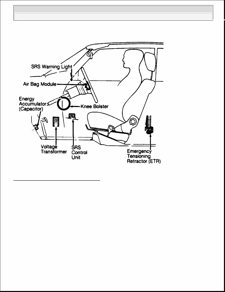
Fig. 1: SRS Component Location (All Models)
Courtesy of MERCEDES-BENZ OF NORTH AMERICA.
DRIVER-SIDE AIR BAG MODULE
Driver-side air bag module consists of a signal carrier, inflatable air bag, gas generator, and ignitor. The gas
generator and ignitor make up the inflator unit mounted permanently to rear of air bag module. A 2-pin
electrical connector with gold-plated terminals is mounted inside inflator unit at rear of air bag module. If 2-pin
connector is disconnected for any reason, a safety shorting spring inside inflator connector spreads open to
touch both terminals. This prevents accidental operation of air bag system by static electricity or careless
handling.
ELECTRICAL SYSTEM
SRS wiring harness outside housing is Yellow. All SRS connectors between air bag module and SRS control
unit have gold-plated terminals for maximum conductivity. When SRS 2-pin connectors are disconnected, a
safety shorting spring inside each connector spreads open to touch both terminals. Safety shorting spring
prevents accidental operation of air bag system by static electricity or careless handling. Safety shorting spring
1992 Mercedes-Benz 500SL
AIR BAG RESTRAINT SYSTEM 1992 ACCESSORIES/SAFETY EQUIPMENT Mercedes-Benz Air Bags

contact is automatically disconnected when SRS connectors are reconnected.
EMERGENCY TENSIONING RETRACTOR (ETR)
The ETR seat belt assembly consists of a gas generator, cable pulley, clutch, guide tube, automatic seat belt
retractor reel, and piston with cable. The complete unit is installed in the right door "B" pillar, in place of
standard belt reel unit. The ETR unit is electrically connected to SRS system by a double pin connector.
When ETR unit wiring connector is disconnected, unit is automatically shorted by a safety shorting spring
inside connector. This prevents accidental operation of ETR system by static electricity or careless handling.
Safety shorting spring contact is automatically disconnected when SRS connectors are reconnected.
The moment an electrical impulse is transmitted from SRS control unit to ETR gas generator to ignite a solid
propellant, a quantity of non-toxic nitrogen gas is produced. The gas accelerates piston and cable in upward
direction in tube. The cable transmits a turning torque to pulley, causing a shear pin to break off, which
connects pulley to wind-up shaft. The wind-up shaft is turned back to eliminate any slack. This action pulls the
seat belt snugly against front occupant in milliseconds.
ENERGY ACCUMULATOR (CAPACITOR)
On 500E models, the energy accumulator or capacitor is a separate SRS component. On all other models,
energy accumulator or capacitor is an integral component of SRS control unit. Capacitor is used to supply
power to SRS control unit if normal power source (battery voltage) is interrupted. If capacitor fails, SRS
warning light on instrument cluster will remain on.
PASSENGER-SIDE AIR BAG MODULE
Passenger-side air bag module consists of an inflatable air bag, 2 gas generators, and 2 ignitors. The air bag
module is mounted in place of glove box, and includes a knee bolster. The 2 gas generators are ignited 15
milliseconds apart to achieve a slower inflation of air bag. The air bag will be fully inflated in about 35
milliseconds. The gas is then quickly released by a filtered ventilation area on windshield side of air bag,
causing air bag to collapse.
A 2-pin connector, with gold-plated terminals, is mounted to inflator unit at rear of air bag module. If 2-pin
connector is disconnected for any reason, a safety shorting spring inside connector spreads open to touch both
terminals, preventing accidental operation of system by static electricity or careless handling.
SLIP RING ASSEMBLY
Slip ring assembly is mounted to bottom side of steering wheel. The slip ring assembly ensures positive
electrical connection between SRS control unit and air bag module when used in conjunction with carbon
contacts mounted in steering column. Carbon contacts constantly rub against slip ring surfaces on bottom of
steering wheel.
SRS CONTROL UNIT
SRS control unit is located under center console, forward of shifter, and is bolted to transmission tunnel. SRS
1992 Mercedes-Benz 500SL
AIR BAG RESTRAINT SYSTEM 1992 ACCESSORIES/SAFETY EQUIPMENT Mercedes-Benz Air Bags

control unit incorporates an electrical sensor to detect deceleration rate, a mercury switch to override threshold
evaluation switch, a microprocessor and a memory system to process and retain information (even after main
power supply has failed).
SRS control unit monitors, detects and evaluates front-to-rear vehicle deceleration and acceleration rates, and
processes this information through an internal dual threshold evaluation switch. When a preset threshold value
(maximum deceleration rate) is exceeded, appropriate air bag deployment is activated according to evaluated
seat belt sensor status information (regardless of whether or not the passenger-side seat belt is buckled).
The SRS control unit monitors and records the combination of "G" force and change in speed (deceleration and
acceleration). All of the following are required to activate SRS: high "G" force, closed mercury switch, and very
rapid deceleration or acceleration. Consequently SRS control unit cannot be activated by a single hammer blow
or other similar influence, which only produces high "G" force.
The sharp deceleration produced by a collision causes the mercury switch to close, while SRS control unit's
electrical sensor simultaneously determines whether or not the impact is sufficient to trigger gas generator.
Activating SRS requires that both the mercury switch and electrical sensor detect a collision.
Two types of SRS control units are used. One unit contains a 12-pin connector to be used on vehicles without
passenger-side air bag. The other unit contains a 16-pin connector to control driver-side and passenger-side air
bags. Both SRS control units function as a diagnostic monitor, which continuously monitors operation of
complete SRS system and records any faults, regardless of ignition switch position or engine operation.
SRS control unit will activate SRS warning light in the instrument panel until a fault is corrected and SRS
memory is cleared. SRS control unit is powered by energy accumulator (capacitor) if normal power source
(battery voltage) is interrupted at any time.
SRS WARNING LIGHT
When ignition is turned on, SRS warning light glows with other instrument panel lights. If no faults are detected
in SRS, warning light will go out after 4-10 seconds with engine off or will go out immediately when engine is
started. If SRS warning light remains on, a fault is indicated in SRS. SRS warning light will remain on until
fault is corrected. If SRS warning light fails to glow when ignition is turned on, bulb is faulty and/or wire to
bulb is shorted to ground.
SERVICING
SRS/AIR BAG label on driver-side door latch post indicates SRS replacement date for driver and passenger air
bag units, and SRS control unit. All SRS components must be thoroughly inspected, including wiring harness.
Before component replacement, check for SRS fault codes by performing system operation check. See
SYSTEM OPERATION CHECK . SRS service life is 10 years from manufactured date, or 10 years from
SRS replacement date after accident related repairs are completed.
POST-COLLISION INSPECTION
After vehicle is involved in a collision, manufacturer recommends replacing all SRS components, with the
exception of an undamaged SRS Yellow wiring harness. If any part of SRS Yellow wiring harness is damaged,
1992 Mercedes-Benz 500SL
AIR BAG RESTRAINT SYSTEM 1992 ACCESSORIES/SAFETY EQUIPMENT Mercedes-Benz Air Bags

DO NOT repair wiring harness, replace complete wiring harness. ALL SRS components include: SRS control
unit, all air bag modules, passenger ETR seat belt assembly and steering wheel (with attached slip ring
assembly).
ADJUSTMENTS
SRS adjustment is not required.
DISPOSAL PROCEDURES
Several situations may arise requiring some form of disposal action, including:
Scrapping a vehicle containing a deployed air bag module and/or ETR.
Scrapping a vehicle with a live air bag module and/or ETR.
Disposal of a live but electrically faulty air bag module and/or ETR.
Disposal of a deployed air bag module and/or ETR.
DEPLOYED AIR BAG OR ETR
Deployed air bag module and/or ETR unit can be thrown away. None of its components are reusable. Deployed
air bag module is NOT classified as hazardous material.
SCRAPPED VEHICLE
1. Before proceeding, follow service precautions. See SERVICE PRECAUTIONS . Move vehicle
outdoors to a remote area, away from workshop and other personnel. Disconnect and shield negative
battery cable. Open all vehicle windows and doors. Ensure air bag module is secured to steering wheel,
and passenger air bag (if equipped) is secured to dash. Ensure ETR seat belt assemblies are secured to "B"
pillars and all seat belt buckles are latched. Remove loose objects from front seat. DO NOT allow anyone
inside vehicle.
2. Locate and disconnect SRS Red connector. See SRS RED CONNECTOR LOCATION table under
DISABLING & ACTIVATING AIR BAG SYSTEM. See Fig. 3 -5. Using Ignition Trigger Device (126-
589-00-90-00), connect ignition trigger device connector to SRS Red connector. Move away from
vehicle, as far as trigger device wiring will allow.
WARNING: An undeployed air bag module or ETR should never be disposed of
without first being deployed. See SCRAPPED VEHICLE . If deployment is
not possible, contact vehicle manufacturer for further instructions.
WARNING: An undeployed air bag module and/or ETR seat belt CANNOT be disposed
of without first being deployed. If this is not possible through procedures
outlined below, contact vehicle manufacturer for further instructions.
Perform remote deployment outdoors. Keep all personnel at least 20 feet
away.
1992 Mercedes-Benz 500SL
AIR BAG RESTRAINT SYSTEM 1992 ACCESSORIES/SAFETY EQUIPMENT Mercedes-Benz Air Bags

3. To deploy air bags, turn rotary switch on trigger device to position No. 4. Depress both push buttons at
same time. Air bag material should be visible in vehicle. Trigger device warning light in upper right
corner of box should glow if SRS air bag ignited. If air bag material is not visible, but trigger device
warning light glows, air bag module is faulty. See UNDEPLOYED AIR BAG/ETR .
4. To deploy ETR seat belt, turn rotary switch on trigger device to position No. 2. Depress both push buttons
at same time. Trigger device warning light in upper right corner of box should glow if ETR seat belt
ignited. If trigger device warning light glows, but passenger seat belt is NOT tight against seat back, ETR
is faulty. See UNDEPLOYED AIR BAG/ETR.
UNDEPLOYED AIR BAG/ETR
After deploying procedures and/or diagnostic testing have confirmed air bag module and/or ETR is
undeployable, contact vehicle manufacturer for proper disposal instructions.
REMOVAL & INSTALLATION
DRIVER-SIDE AIR BAG MODULE
Removal & Installation
1. Before proceeding, follow air bag service precautions. See SERVICE PRECAUTIONS . Disable air bag
system. See DISABLING & ACTIVATING AIR BAG SYSTEM .
2. Using Torx TX30 bit with long shank, remove 2 Torx screws from rear of steering wheel. Lift off air bag
module enough to unplug connector from rear of module. Place module away from work area, with pad
facing upward.
3. To install, reverse removal procedure. Tighten Torx screws to 53 INCH lbs. (6 N.m). Activate air bag
system. Perform system operation check to ensure system is functioning properly. See SYSTEM
OPERATION CHECK .
ENERGY ACCUMULATOR (CAPACITOR)
Removal & Installation (500E)
1. Before proceeding, follow air bag service precautions. See SERVICE PRECAUTIONS . Disable air bag
system. See DISABLING & ACTIVATING AIR BAG SYSTEM .
2. On driver-side foot rest panel, rotate plastic retaining clips 90 degrees and pull off clips. Raise foot rest
panel to locate capacitor position. Remove 2 screws in center of foot rest panel that retain capacitor to
WARNING: Failure to follow air bag service precautions may result in air bag
deployment and personal injury. See SERVICE PRECAUTIONS . After
component replacement, perform a system operation check to ensure
proper system operation. See SYSTEM OPERATION CHECK .
NOTE: Air bag module and steering wheel must be replaced following a collision in
which air bag was deployed.
1992 Mercedes-Benz 500SL
AIR BAG RESTRAINT SYSTEM 1992 ACCESSORIES/SAFETY EQUIPMENT Mercedes-Benz Air Bags

under side of panel. Remove foot rest panel. Disconnect capacitor connector and remove capacitor.
3. To install, reverse removal procedures. Activate air bag system. Perform system operation check to
ensure system is functioning properly. See SYSTEM OPERATION CHECK .
PASSENGER-SIDE AIR BAG MODULE
SLIP RING ASSEMBLY
Removal & Installation
1. Before proceeding, follow air bag service precautions. See SERVICE PRECAUTIONS . Disable air bag
system. See DISABLING & ACTIVATING AIR BAG SYSTEM . Remove air bag module. See
DRIVER - SIDE AIR BAG MODULE under REMOVAL & INSTALLATION. Remove steering wheel.
See STEERING WHEEL .
2. To remove slip ring from steering wheel, remove horn contacts and support springs from center of
steering wheel. From inside steering wheel hub opening, disconnect horn wiring connector, and remove
Phillips head screws retaining slip ring to bottom of steering wheel.
3. Remove steering wheel hub metal assembly. Remove slip ring by guiding slip ring wiring through
steering wheel opening.
4. To remove carbon contacts from steering column, remove steering column cover plate retaining screws (if
equipped). Remove cover plate off steering shaft/column. Locate SRS carbon contacts at about 2 o'clock
position. See Fig. 3 -5. Remove SRS carbon contacts from steering column.
5. On some models, carbon contacts are held in place by plastic retainers. Pry out retainers. Unplug wiring
and replace each contact/retainer as a complete unit.
6. To install, reverse removal procedures. Activate air bag system. Perform system operation check to
ensure system is functioning properly. See SYSTEM OPERATION CHECK .
SRS CONTROL UNIT
NOTE: Information is not available from manufacturer.
1992 Mercedes-Benz 500SL
AIR BAG RESTRAINT SYSTEM 1992 ACCESSORIES/SAFETY EQUIPMENT Mercedes-Benz Air Bags
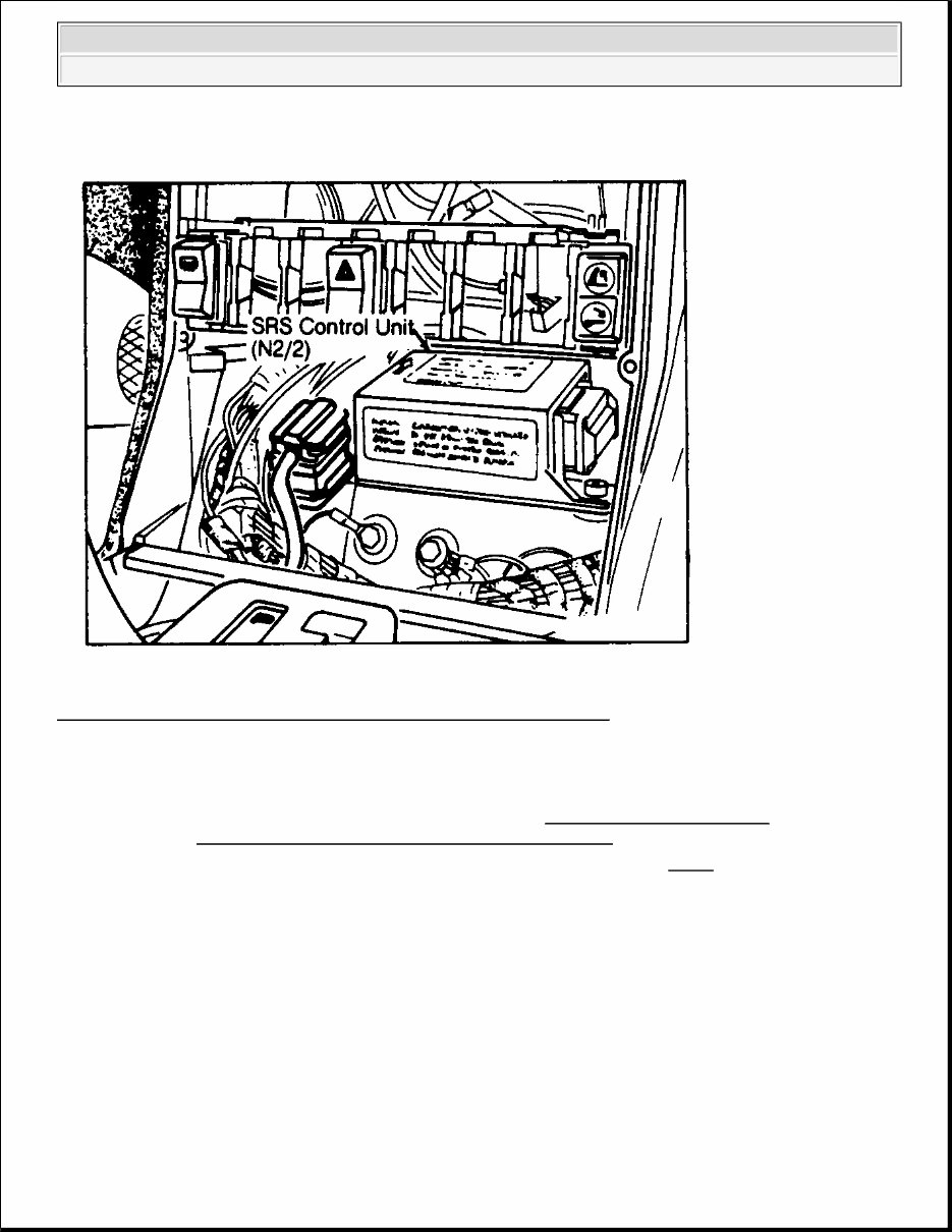
Fig. 2: SRS Control Unit With Radio Removed Location (All Models)
Courtesy of MERCEDES-BENZ OF NORTH AMERICA.
Removal (500E)
1. Before proceeding, follow air bag service precautions. See SERVICE PRECAUTIONS . Disable air bag
system. See DISABLING & ACTIVATING AIR BAG SYSTEM .
2. Remove gearshift lever cover. Remove radio. Locate SRS control unit. See Fig. 2 . If SRS control unit
harness connector can be disconnected at control unit, go to step 4). If SRS control unit harness connector
CAN NOT be disconnected at control unit, remove driver-side floor carpet and locate foot rest panel. At
driver-side foot rest panel rotate plastic retaining clips 90 degrees. Pull off clips. Remove driver-side foot
rest panel, and left kick panel.
3. Loosen or remove all SRS control unit wiring harness retaining clips: in driver-side floor, from foot rest
area, along bottom of kick panel, in front of driver-side seat, and up into center console. Pull SRS control
unit wiring harness out of gear shift lever area until harness is removed from driver-side floor area.
4. Unscrew SRS control unit mounting bolts using Torx TX30 bit. Remove SRS control unit and wiring
harness through radio opening in center console face plate. Disconnect SRS control unit harness
connector.
1992 Mercedes-Benz 500SL
AIR BAG RESTRAINT SYSTEM 1992 ACCESSORIES/SAFETY EQUIPMENT Mercedes-Benz Air Bags

Installation
1. Install SRS control unit with top arrow pointing toward front of vehicle. Tighten Torx TX30 bolts to
specification. See TORQUE SPECIFICATIONS table. Connect SRS control unit harness connector. If
wiring harness is attached to control unit, route new SRS wiring harness into original position and
connect all SRS electrical connectors together.
2. Activate air bag system. Check SRS warning light operation. See SYSTEM OPERATION CHECK . If
SRS operates properly, disable air bag system. See DISABLING & ACTIVATING AIR BAG
SYSTEM . Complete installation by reversing removal procedures. Activate air bag system. Perform
SYSTEM OPERATION CHECK. If fault codes are present and/or SRS does not function properly, see
DIAGNOSIS & TESTING .
Removal (500SEL)
1. Before proceeding, follow air bag service precautions. See SERVICE PRECAUTIONS . Disable air bag
system. See DISABLING & ACTIVATING AIR BAG SYSTEM .
2. Remove ash tray and ash tray housing bracket. Remove A/C control knobs and radio knobs. Remove
center instrument panel face plate by pulling outward and downward. Disconnect wiring connections
from switches on rear of face plate. Remove radio. Locate SRS control unit. See Fig. 6 and Fig. 2 .
Remove SRS wiring harness connector from SRS control unit.
3. Unscrew SRS control unit mounting bolts using Torx TX30 bit. Remove SRS control unit out through
radio bracket opening in center console.
Installation
1. Install SRS control unit with top arrow pointing toward front of vehicle. Tighten SRS control unit Torx
TX30 bolts to specification. See TORQUE SPECIFICATIONS table. Plug in SRS connector to SRS
control unit.
2. Before completing center instrument panel installation, activate air bag system. Check SRS warning light
operation. See SYSTEM OPERATION CHECK . If fault codes are present and/or SRS does not
function properly, see DIAGNOSIS & TESTING .
3. If SRS functions properly, disable air bag system. See DISABLING & ACTIVATING AIR BAG
SYSTEM . Continue installation procedures by reversing removal procedures. After installation
procedures are completed, activate air bag system.
Removal (500SL)
1. Before proceeding, follow air bag service precautions. See SERVICE PRECAUTIONS . Disable air bag
system. See DISABLING & ACTIVATING AIR BAG SYSTEM .
2. Pull off control knobs for blower fan and air distribution switches. Unscrew 2 large retaining nuts from
knob recesses. Remove ash tray. Unscrew ash tray housing retaining screws. Remove ash tray housing
from center console.
3. Remove center console A/C-heater face plate by pulling outward and downward. Disconnect wiring
connections from rear of face plate. Unscrew 2 horizontal bolts inside opening between A/C-heater
control wheels.
4. Push air distribution switch toward right side of plate to remove. Push fan blower switch upward to
1992 Mercedes-Benz 500SL
AIR BAG RESTRAINT SYSTEM 1992 ACCESSORIES/SAFETY EQUIPMENT Mercedes-Benz Air Bags
You're Reading a Preview
What's Included?
Fast Download Speeds
Online & Offline Access
Access PDF Contents & Bookmarks
Full Search Facility
Print one or all pages of your manual
$39.99
$51.99
Viewed 21 Times Today


Secure transaction
What's Included?
Fast Download Speeds
Online & Offline Access
Access PDF Contents & Bookmarks
Full Search Facility
Print one or all pages of your manual
$39.99
$51.99
- Complete Factory Service Repair Workshop Manual for Mercedes Benz 500SL 1990-1993.
- Accessible for instant download to your computer, tablet, or smartphone.
- Includes detailed photos & diagrams, covering all repairs, servicing, and troubleshooting procedures.
- Utilized by professional mechanics and technicians, featuring step-by-step instructions and highly detailed exploded diagrams & pictures.
- Printable - you have the option to print out a single page or the entire manual.
- Multi-computer use - this manual can be used on as many computers as required.
- Full version - no limitations or trial periods, and can be used for life.
- Compatibility - fully compatible with all Windows & MAC Computers.
Thanks for considering this manual. Click the button to proceed.


