

Mercedes-Benz 190D 190DB 190SL Service & Repair Manual
What's Included?
Fast Download Speeds
Online & Offline Access
Access PDF Contents & Bookmarks
Full Search Facility
Print one or all pages of your manual
Service Manual
Models 180 to 220 SE
MERCEDES-BENZ OF NORTH AMERICA
l
INC.
Mercedes-Benz
service
;·::J;l"~~·X::ii· .:.
.. .
" ....
"~

.: '1
·1·,
SM 1201
REPRINTED IN USA
Publhhed by the Daimler-Benz Aktiengeselfschafr, Srutlgart-Unlertuerkheim, Export-
Service. RepreduttiDn Dr trcnsletion, in whole Dr in parr, not permitted without
wriHen authori~ation.
PREFACE
This manual was developed as a supplementary manual to the Workshop
Manual Model 190 to extend the coverage to Models 180, 1800, 180b,
180c, 180D, 180Db, 180Dc, 190D, 190Db, 1905L, 2200, 219, 220S and 220SE.
The individual repair procedures are described in detail only if they do not
correspond ta those of Model 190. When there is no difference, reference
is made to the basic Model 190 Workshop Manual. This means that for a
complete description of various repair procedures, both manuals, the
Workshop Manual Model 190 and the Workshop Manual 180 to 220SE, must
be available.
Not covered are the side-valve engine of model 180, diesel engines OM 636
OM 621 of models 180D, 180Db, 180Dc, 190D and 190Db, the fuel injec-
tion system of Model 220SE, the hydraulic-automatic transmission, and the
daublejointed rear axle of model 180 and 180D. These units are covered
in other workshop manuals.
The entire contents of this Workshop Manual are arranged by groups. The
group index serves to locate any particular group. Each group is preceded
by a comprehensive listing of its contents.
Mercedes-Benz of North America, lnc., recommends thor repairs to, and
maintenance of, Mercedes-Benz automobiles performed only by Mercedes-
Benz trained personnel at authorized Mercedes-Benz repair stations.
The information contained in this special publication was originally issued
by Daimler-Benz AG in conjunction with supplementary service literature
only to its authorized dealers. The various repair and maintenance pro-
cedures outlined herein are procedures to be used by trained Mercedes-
Benz service and repair station personnel. Supplementory service literature
is no longer available for this publication .
. Mercedes-Benz of North America, Inc., assumes no liability for any damage
to person or property occasioned by the utilization of this publication to
effect maintenance or repair work on Mercedes-Benz autamobiles.
Reprinted by
MERCEDES-BENZ OF NORTH AMERICA, INC.
v
Location of Model Plate,
Engine, Chassis, and Body Numbers
Apart from exceptions listed below, the location of the Model Plate and the Plates giving the En-
gine, Chassis, and Body Numbers and the Type of Car Finish, is, for Models 180 to 220SE, the
same as on Model 190.
On Models 180 and 180 D the Engine Number Plate is located on top of the timing gear cover.
On Model 190 Sl, the Chassis Number Plate and the Plate giving the Type of Car Finish are
located at the top of the fire wall behind the battery. On Model 220a there is as yet no plate
indicating the type of Car Finish.
To ensure prompt and correct execution of your orders and attention to your inquiries/ please let
us have the following details:
1. Complete Chassis Number
2. Complete Engine Number
3. Complete Body Number
4. Mileage covered
location of Unit Numbers
In your inquiries and orders referring to specific car units such as front axle/ steering gear, trans-
mission/ and rear axle, please quote the Unit Numbers as well. For Models 180 to 220 SE these
Numbers can be found in the some place as on Model 190.
VI
- -~
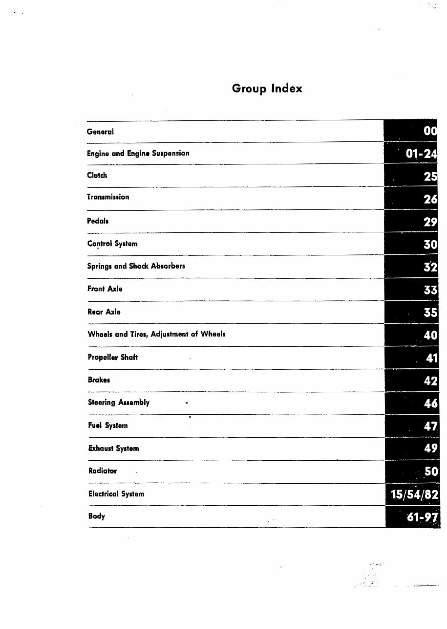
Group Index
General
Engine and Engine Suspension
Clutch
Transmission
Pedals
Co~trol System
Springs and Shock Absorbers
Front Axle
Rear Axle
Wheels and Tires, Adjustment of Wheels
Propeller Shaft
Brakes
Steering Assembly
Fuel System
Exhaust System
Radiator
Electrical System
Body
,::'
..- ---:;_.
,.,.. '
-.~'-" _- --~

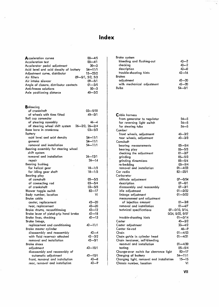
Acceleration curves
Acceleration test
Accelerator pedal adjustment
Acid level and acid density of battery
Adjustment curve, distributor
Air filters
Air intake silencer
Angle of closure, distributor contacts
Anti-freeze salutians
Axle positioning distance
Balancing
of crankshaft
af wheels with tires fitted
Boll cup connector
of steering assembly
of steering wheel shift system
Bose bore in crankcase
Battery
acid level and acid density
general
removal and installation
Bearing assembly for steering wheel
shift system
removal and installation
repair
Bearing bushing
for helical gear
for idling gear shaft
Bearing play
of camshaft
of connecting rod
of crankshaft
Blower toggle switch
Body number, location
Brake cable
center, replacement
rear, replacement
Brake drums, reconditioning
Brake lever of pistol-grip hand brake
Bra ke lines, checking
Brake linings,
replacement and conditioning
Brake master cylinder
disassembly and reassembly
with fluid reservoir attoched
removal and installation
Brake shoes
adjustment
disassembly and reassembly of
automatic adjustment
front, removal and installation
rear, removal and installation
~/S
~/1
30-3
54-111l
15-23/2
09-S/1, 5/2, S/3
09-5/1
01-315
50-3
40-3/2
03-S/10
40-3/1
46-4
26-712, 26-214
03-S/3
54-1111
54-11/1
54-1111
26-1211
26-14
18-1/3
18-1/3
05-5/3
03-514
03-5/3
B2-17
VI
42-20
42-20
42-12
42-1B
42-13
42-11/1
42-4
42-3/2
42-3/1
42-10/1
42-1011
42-8
42-9
Index
Brake system
bleeding and flushing-out
checking
description
trouble-shooting hints
Brakes
adjustment
with mechanical adjustment
Bulbs
Cable harness
from generator to regulator
for reversing light switch
for steering tube
Comber
front wheels, adjustment
rear wheels, adjustment
Camshaft
bearing measurements
bearing play
checking the adjustment
grinding
grinding dimensions
re-bedding
removal and installation
Car radio
Carburetor
altitude adjustment
description
disassembly and reassembly
idle odjustment
linkage adjustment
measurement and adjustment
of injection amount
removal and installation
technical specifications
trouble-shooting hints
Coster
Caster adjustment
Center tie-rod
Chain
Chain guide in cylinder head
Chain tensianer, self-bleeding
removal and installation
testing
Change-over switch for clearance light
Charging of battery
Charging light, removal and installation
Chcssis number, location
42-2
42-2
42-0
42-16
42-20
42-20
S4-0/1
54-S
54-5
54-5
40--3/2
4~3/3
05-5/4
05-5/3
01-317
05-5/3
05-5/4
05-5/4
01-4/23
B2-20/1
07-0/54
07-011
07-3/1
01-3122
01-3122
Ol-31B
01--417
07-0110, 0/14,
0124, 0/32, 0/51
01-3/14
4~3/2
33--412
M-9
01-4/53
01-4/31
01-4/30
05-5/4
B2-17
54-11/1
15--15
VI
VII
' .. ~':-
03-5/3
30--611
54---012
82-17
54-18
01-3/5
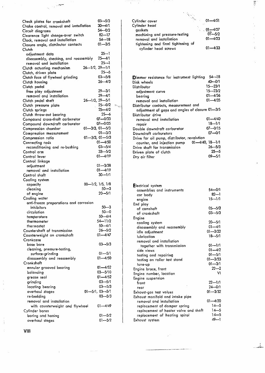
Check plates for crankshaft
Choke control, removal and installation
Circuit diagrams
Clearance light change-over switch
Clock, removal and installation
Closure angle, distributor contacts
Clutch
adjustment data 25-1
disassembly, checking, and reassembly 25-4/1
removal and installation 25-1
Clutch actuating mechanism 26-1/2, 29-111
Clutch, driven plate 25-5
Clutch face of flywheel grinding 03-5/8
Clutch housing 26---413
Clutch pedal
free ploy adjustment 29-3/1
removal and installation 29-4/1
Clutch pedal shaft 26-112, 29-5/1
Clutch pressure plote 25-012 '" r, ',;::'
Clutch springs 25-4/2
Clutch throw-out bearing 25--6
Compound cross-draft carburetor 07......{)133
Compound downdraft carburetor 07"""{)125
Compression chamber 01-313, 01-5/3
Compression measurement 01-3/3
Compression ratio 01-313, 01-513
Connecting rods 01-4/50
reconditioning and re-bushinq 03-5/4
Control arm 33-512
Control lever 01-4/19
Control linkage
adjustment 01-3/3B
removal and installation 01-4/19
Control shaft 31}-1/1
Cooling system
capacity
cleaning
of engine
Cooling water
anti-freeze preparations and corrosion
inhibitors
circu lotion
temperature
thermometer
thermostat
Countershaft of transmission
Counterweight on crankshaft
Crankcase
bose bore
cleaning, pressure-testing,
surfoce-grinding
disassembly and reassembly
Crankshaft
annular grooved bearing
balancing
grease seal
grinding
locating bearing
overhaul stages
re-bedding
removol and installation
with counterweight and flywheel
Cylinder bores
boring and honing
overhaul stages
VIII
00-112, 115, lIB
51}-3
21}-5/1
51}-3
50--0
50--614
54-1112
50--6/1
26-5/2
01-4147
03-5/3
01-5/1
01-4/50
01-4152
03-5110
01-4/52
03-5/1
03-5/3
01-5/1, 03-5/1
03-5/3
01-4/49
01-512
01-5/2
Cylinder cover
Cylinder head
gaskets
machining and pressure-testing
removal and installation
tightening and final tightening of
cylinder head screws
01-4151
. (}k-
4127
01;_512
01-4123
01-4133
Dimmer resistance for instrument lighting 54-1B
Disk wheels 4~/l
Distributor 15-23/1
15-2312
01-4/36
01-4/35
adjustment curve
bearing
removal ond installation
Distributor contocts, measurement and
adjustment of gaps and angles of closure 01-3/5
Distributor drive
01-4140
18-111
07-0115
07......{)/l
removal and installation
repair
Double downdraft carburetor
Downdraft corburetors
Drive for oil pump, distributor, revolution
counter, and injection pump 01-4/40, 18-111
Drive shaft for transmission 26-513
Driven plate of clutch 25-5
Dry oir filter 09-5/1
Electrical system
ossemblies and instruments
cor body
engine
End ploy
of camshaft
of crankshaft
Engine
cooling system
disassembly and reassembly
idle adjustment
lubrication
removal and installation
together with transmission
side views
testing and repairing
testing on roller test stand
tune-up
Engine broce, front
Engine number, location
Engine suspension
front
rear
Exhaust-gas test values
Exhaust manifold and intake pipe
removal and installation
replacement of damper spring
replacement of heater valve and shaft
replacement of heating spiral
Exhaust system
54......{)/1
82-1
15-111
05-513
03-5/3
21}-5/1
01-4/1
01-3m
18-511
01-111
01-412
01-5/1
01-3133
01-3/1
22-2
VI
22-1/1
24......{)/1
01-3/32
01-4/20
14-5
14-5
14-5
49-1
I
....d
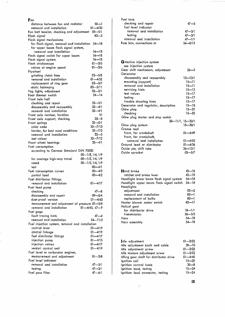
Fan
distance between fan and radiator 50--1
removal and installation 01-4/33
Fan belt tension, checking and adjustment 50-5/1
Flash signal 82-3
Flash signal mechanisms
for flash signal, removal and installation 54-18
for upper beam flash signal system,
removal and installation
Flash signal switch for upper beam
Flash signal system
Flash stroboscope
values at engine speed
Flywheel
grinding clutch face
removal and installation
replacement of ring gear
.stotic balancing
Fog lights, adjustment
Foot dimmer switch
Front axle half
Fuel consumption curves
partial load
Fuel distributor fittings,
removal and installation
Fuel feed pump
checking 47-8
disassembly and repair 09-514
dust-proof version 01-4143
measurement and adjustment of pressure 01-3/8
removal and installation 01-4143 47-9
Fuel gage r
fault tracing hints
removal and installation
Fuel injection system, removal and
control lever
control linkage
fuel distributor fittings
injection pump
injection valves
venturi control unit
Fuel level in carburetor engines,
measurement and adjustment
Fuel level indicator
removal and installation
testing
Fuel pass filter
checking and repair
disassembly and reassembly
removal and installation
Front axle number, location
Front axle support, checking
Front springs
color code
harder, for bod rood conditions
removal and installation
test values
Front wheel bearings
Fuel consumption
according to German Standard
for overage high-way travel
rated
test
54-18
54-18
54-18
01-3/5
01-3/6
03-5/8
01-4152
03-517
03-5/11
82-211
54-14
33-5/1
33--4/1
33--411
VI
33-8
32-0/1
32-7113
32-712
32-5
32-7112
33-4/1
DIN 70030
00--113,1/6,1/9
00-1/3,1/6,1/9
00--1/3,1/6,1/9
00-4/1
00-412
00-4/2
01-41l7
47-4
54-1112
installation
01-4/19
01-4/19
01-4/17
01-4/15
01-4/17
01-4/19
01-3/8
47-311
47-3/1
47--611
testing
trouble shooting hints
Generator and regulator, description
Glow plug
checking
Glow plug starter and stop switch
3O-llf1, 15-33/1
15-30/1
Fuel tonk
checking and repair
fuel level indicator
removal and installation
testing
removal and installation
Fuse box, connections at
Gasoline injection system
see injection system
Gear shift mechanism, adjustment
Generator
disassembly and reassembly
mounting (support)
removal and installation
servicing hints
test values
Glow plug system
Grease seal
front, for crankshaft
front, for crankshaft,
removal 'and installation
Ground lead at distributor
Guide pin, shift tube
Guide sprocket
Hand broke
ratchet and broke lever
Headlight lower beam flash signal system
Headlight upper beam flash signal switch
Headlights
adjustment
removal and installation
replacement of bulbs
Heater blower motor switch
Helical gear
for distributor drive
transmission
Horn
Horn assembly
Idle adjustment
Idle adjustment knob and coble
Idle adjustment screw
Idle mixture adjustment screw
Idling gear shaft for distributor drive
Ignition coil
Ignition control knob
Ignition lead, testing
Ignition lead connector, testing
47-5
47-311
47-311
47-111
54-0/13
26-3
15-13/1
15-11
15-11
15-12
15-17
15-17
15-17
15-10
15-31
15-32
01-4149
01-4152
01-4/36
26-1211
05-517
42-18
42-18
54-18
54-18
82-2
82-1
82-1
82-17
18-1/1
26-5/3
54-18
54-18
01-3/22
30-10
01-3122
01-3122
01-4/40
15-22
30-8
15-24
15-24
IX
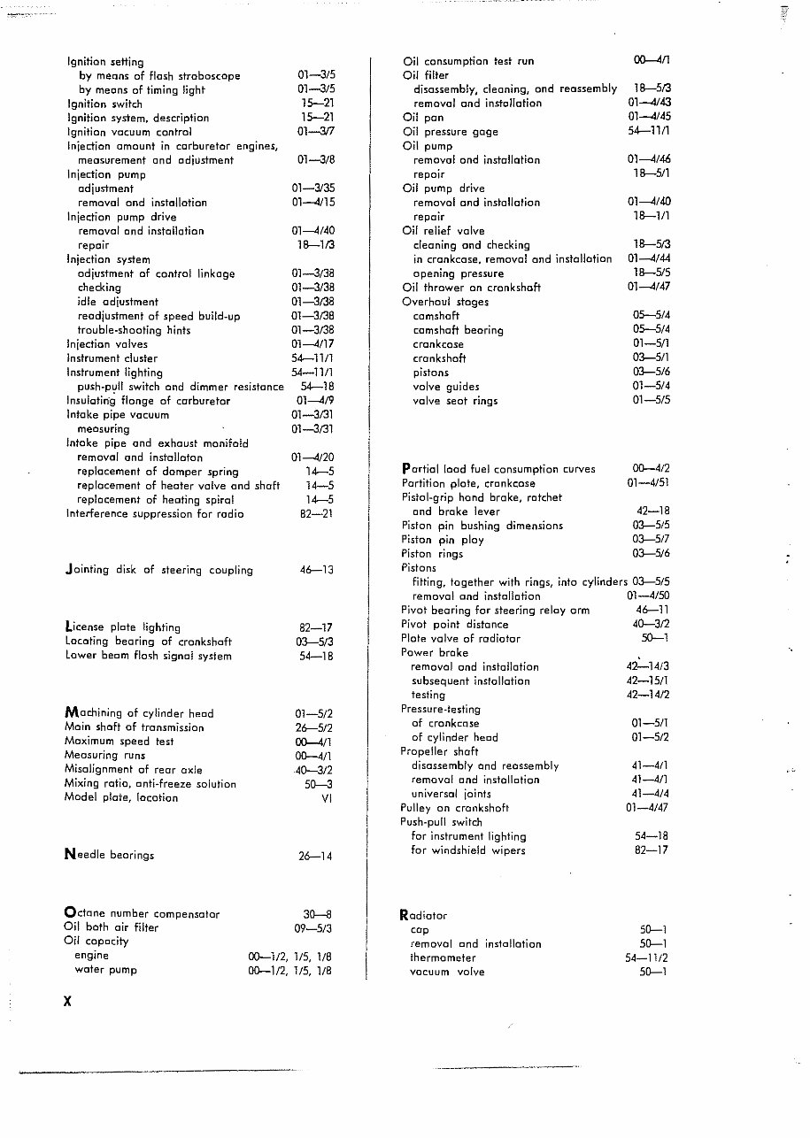
Ignition setting
by means of flash stroboscope
by means of timing light
Ignition switch
Ignition system, description
Ignition vocuurn control
Injection amount in carburetor engines,
measurement and adjustment
Injection pump
adjustment
removal and installotion
Injection pump drive
removo! and installation
repair
Injection system
adjustment of control linkage
checking
idle adjustment
readjustment of speed build-up
trouble-shooting hints
Injection valves
Instrument cluster
Instrument lighting
push-pull switch ond dimmer resistance
Insulating flange of carburetor
Intake pipe vacuum
meosuring
Intake pipe and exhoust manifold
removal and installaton
replacement of domper spring
replacement of heoter valve and shaft
replacement of heating spiral
Interference suppression for radio
Jointing disk of steering coupling
License plote lighting
locating bearing of crankshaft
lower becm flash signal system
Machining of cylinder heod
Main shaft of transmission
Maximum speed test
Measuring runs
Misalignment of rear axle
Mixing ratio, anti·freeze solution
Model plate, location
Needle bearings
Ochme number compensntcr
Oil both air filter
Oil copocity
engine
water pump
01-3/5
01-315
15--21
15--21
01-3/7
01-3/8
01-3/35
01---4115
01---.4140
18-113
01-3/38
01-3/38
01-3138
01-3138
01-3/38
01---.4/17
54-1111
54-11/1
54-18
01---.4/9
01-3131
01-3131
01---.4120
14-5
14-5
14-5
82-21
46--13
82-17
03-5/3
54-18
01-5/2
26--5/2
~/1
~4/1
40-3/2
50-3
VI
26--14
30-8
09-5/3
00-112, 115, 1/8
~1!2. 115, 1/8
x
portial load fuel consumption curves
Portition plate, cronkcose
Pistol-grip hand brake, ratchet
and brake lever
Piston pin bushing dimensions
Piston pin ploy
Piston rings
Pistons
fitting, together with rings, into cylinders 03-5/5
removal and instollotion 01-4/50
Pivot bearing for steering relay arm 46--11
Pivot point distance 40-312
Plate valve of radiatar 50-1
Power brake
Oil consumption test run
Oil filter
disassembly. cleaning, and reassembly
removol and installation
Oil pan
Oil pressure gage
Oil pump
removal and installation
repair
Oil pump drive
removol and installation
repair
Oil relief valve
cleaning and checking
in crankcase. removal and installation
opening pressure
Oil thrower on crankshaft
Overhaul stages
camshaft
camshaft beoring
crankcase
crankshaft
pistons
valve guides
valve seat rings
removal and installation
subsequent installation
testing
Pressure-testing
of crankcase
of cylinder heod
Propeller shaft
disossembly and reassembly
removal ond installotion
universal joints
Pulley on crankshaft
Push-pull switch
For instrument lighting
For windshield wipers
Radiator
cap
removal end installation
thermometer
vacuum valve
18-513
01---4/43
01---4145
54-11/1
01---.4/46
18-5/1
01---.4140
18-111
18-513
01---.4/44
18-515
01---.4147
05--514
05--5/4
01-5/1
03-5/1
03-5/6
01-5/4
01-5/5
~4/2
01-4151
42-18
03-5/5
03-517
03-5/6
42-14/3
42-15/1
42-14/2
OJ-5/1
01-5/2
41-411
41-4/1
41-4/4
01-4/47
j.';"
54-18
82-17
50-1
50-1
54-11/2
50-1
You're Reading a Preview
What's Included?
Fast Download Speeds
Online & Offline Access
Access PDF Contents & Bookmarks
Full Search Facility
Print one or all pages of your manual
$41.99
$54.99
Viewed 12 Times Today


Secure transaction
What's Included?
Fast Download Speeds
Online & Offline Access
Access PDF Contents & Bookmarks
Full Search Facility
Print one or all pages of your manual
$41.99
$54.99
Thank you for considering this comprehensive Workshop Service Repair Manual for the Mercedes Benz 190D, 190DB, and 190SL.
This manual is an invaluable resource, covering every Service & Repair Procedure necessary for professional mechanics and DIY enthusiasts alike.
With easy-to-follow step-by-step instructions and detailed illustrations, this manual empowers you to save on repair costs by performing maintenance and repairs on your own.
Upon purchase, the manual is yours to keep forever. You have the flexibility to print specific pages, chapters, or the entire manual. Additionally, it can be conveniently accessed on your tablet or smartphone.
MODELS COVERED:
- All Models/Engines/Trim/Transmissions Types Are Covered.
CONTENTS:
- This high-quality Service Repair Workshop Manual encompasses all repair procedures from A to Z, ensuring that every repair and service procedure is comprehensively addressed.
COMPUTER REQUIREMENTS:
- This downloadable Manual is compatible with all PC & MAC Computers, tablets, and mobile phones. The only software required is Adobe Reader, which is typically pre-installed on most computers. If not, it can be downloaded for free.
INSTANT DELIVERY:
- Upon payment via Visa, MasterCard, or PayPal, the manual will be instantly emailed to the address provided during checkout.
Customer Satisfaction Guaranteed.


