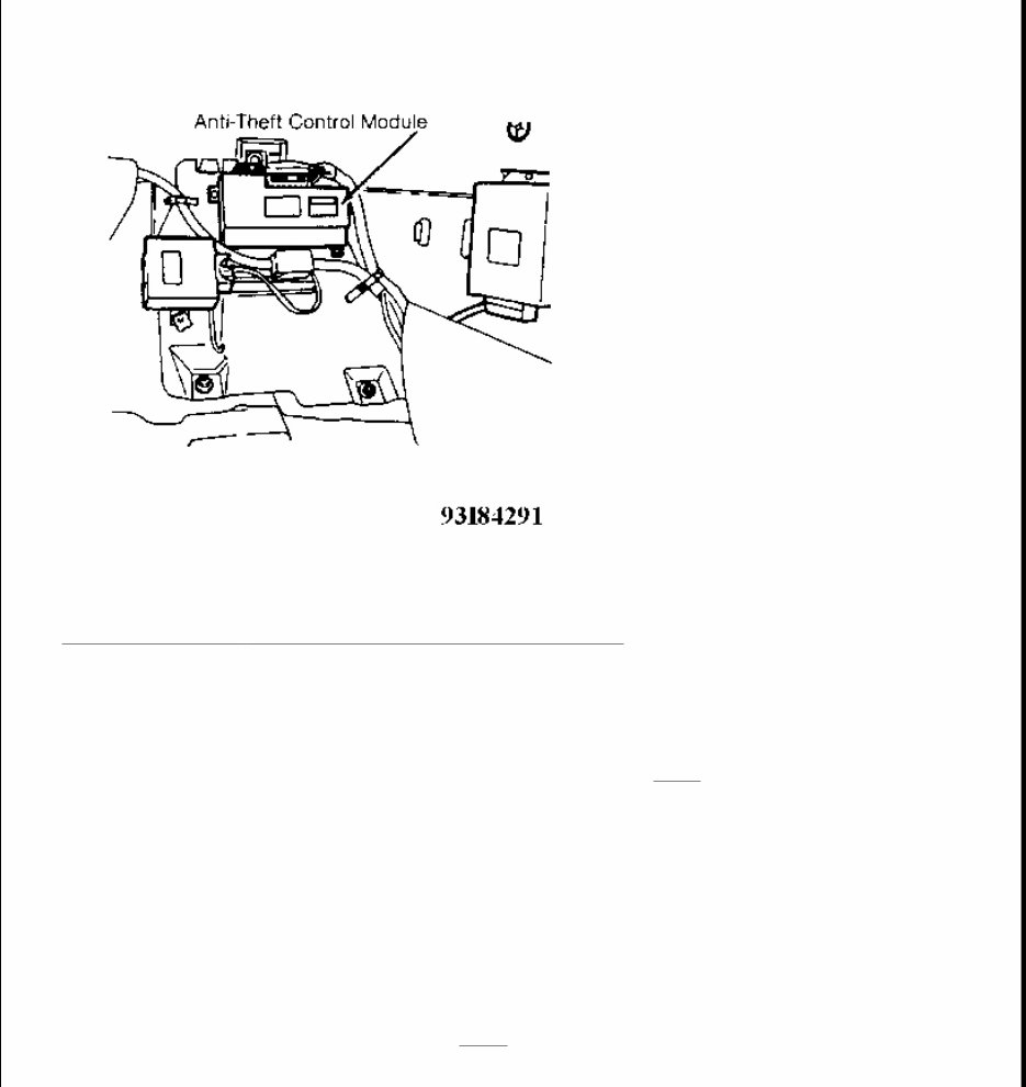
ANTI-THEFT SYSTEM 1994 ACCESSORIES/SAFETY EQUIPMENT Mercedes-Benz Anti-Theft System DESCRIPTION & OPERATION The anti-theft system is a contact controlled system. When the anti-theft system is activated, an audio horn will sound and exterior lights will flash. The anti-theft system monitors the radio, all doors, hood and trunk lid position. TROUBLE SHOOTING TESTING CIRCUIT CHECK 1. Disconnect anti-theft control module 14-pin wiring harness connector. Anti-theft control module is located in right footwell below foot support. See Fig. 1 . Ensure wiring harness connector terminals are clean and tight. 2. Connect voltmeter positive lead to connector terminal No. 3 (Red/White wire) and negative lead to terminal No. 2 (Brown wire). If 11 volts or more are present, go to next step. If less than 11 volts are not present, repair open circuit. 3. Disconnect anti-theft control module 8-pin wiring harness connector. Ensure wiring harness connector terminals are clean and tight. Connect voltmeter negative lead to 14-pin connector terminal No. 2 (Brown wire). 4. Alternately connect voltmeter positive lead to 8-pin connector terminal No. 4 (Red/White wire) and No. 5 (Red/Yellow wire). If 11 volts or more are present, circuit is okay and testing is complete. If less than 11 volts are present, go to next step. 5. Check voltage between ground and input side of auxiliary fuses. If less than 11 volts are not present, repair open circuit. If 11 volts or more are present, repair open or shorted circuit between fuse(s) and anti- theft control module 8-pin wiring harness connector. NOTE: Trouble shooting information is not available from manufacturer. NOTE: Ensure battery is fully charged and all fuses are okay.
Fig. 1: Locating Anti - Theft Control Module (E320, E420 & E500) Courtesy of MERCEDES-BENZ OF NORTH AMERICA FRONT DOOR SWITCH CHECK 1. Ensure doors are closed. Disconnect anti-theft control module 8-pin wiring harness connector. Anti-theft control module is located in right footwell below foot support. See Fig. 1 . Ensure wiring harness connector terminals are clean and tight. 2. Connect ohmmeter between connector terminal No. 6 (Yellow/Blue wire) and ground. Insert master key in left door lock and turn counterclockwise. Insert master key in right door lock and turn clockwise. If 0.5 ohm is present when key is in lock and held as specified, circuit is okay and testing is complete. If resistance is not as specified, go to next step. 3. Ensure doors are closed. Connect ohmmeter between connector terminal No. 7 (Green/Yellow wire) and ground. Insert master key in left door lock and turn counterclockwise. Insert master key in right door lock and turn clockwise. If 0.5 ohm is present when key is in lock and held as specified, circuit is okay and testing is complete. If resistance is not as specified, go to next step. 4. Remove connector from faulty switch. Place door latch in the closed position. Connect ohmmeter between switch terminals No. 1 and 3. See Fig. 2 . Insert master key in left door lock and turn clockwise. Insert master key in right door lock and turn counterclockwise. If 0.5 ohm or less is present when key is in lock and held as specified, go to next step. If more than 0.5 ohm is present when key is in lock and held
as specified, replace door switch. 5. With switch connector removed and door latch in the closed position, connect ohmmeter between switch terminals No. 1 and 2. See Fig. 2 . Insert master key in left door lock and turn counterclockwise. Insert master key in right door lock and turn clockwise. If 0.5 ohm or less is present when key is in lock and held as specified, go to next step. If more than 0.5 ohm is present when key is in lock and held as specified, replace door switch. 6. Disconnect anti-theft control module 8-pin and 14-pin wiring harness connector (if necessary). Check for continuity between door switch connector terminal No. 1 and 14-pin connector terminal No. 2 (Brown wire). 7. Check for continuity between door switch connector terminal No. 2 and 8-pin connector terminal No. 7 (Green/Yellow wire). Check for continuity between door switch connector terminal No. 3 and 8-pin connector terminal No. 6 (Yellow/Blue wire). If continuity is not present, repair circuit as necessary. If continuity is present, circuits are okay. Replace anti-theft control module. Fig. 2: Door Switch Connector Terminal ID (E320, E420 & E500) Courtesy of MERCEDES-BENZ OF NORTH AMERICA TRUNK SWITCH CIRCUIT CHECK 1. Ensure doors are closed. Disconnect anti-theft control module 14-pin wiring harness connector. Anti-theft control module is located in right footwell below foot support. See Fig. 1 . Ensure wiring harness connector terminals are clean and tight. 2. Connect voltmeter negative lead to terminal No. 10 (Black wire). Connect positive lead to connector terminal No. 3 (Red/White wire). If 11 volts or more are present, circuit is okay and testing is complete. If less than 11 volts are present, repair circuit as necessary. STARTER SWITCH DISABLE CIRCUIT CHECK
1. Disconnect anti-theft control module 14-pin wiring harness connector. Anti-theft control module is located in right footwell below foot support. See Fig. 1 . Ensure wiring harness connector terminals are clean and tight. 2. Connect voltmeter negative lead to terminal No. 2 (Brown wire). Connect positive lead to connector terminal No. 14 (Black/Red wire). Turn ignition switch to the No. 2 position. If 11 volts or more are present, circuit is okay and testing is complete. If less than 11 volts are present, repair circuit as necessary. ANTI-THEFT ALARM HORN CHECK 1. Disconnect anti-theft control module 8-pin wiring harness connector. Anti-theft control module is located in right footwell below foot support. See Fig. 1 . Ensure wiring harness connector terminals are clean and tight. 2. Connect ohmmeter between terminal No. 1 (Black/Yellow/Red wire) and ground. If zero ohms are present, go to next step. If zero ohms are not present, check Black/Yellow/Red wire for continuity and repair as necessary. 3. Using a jumper wire, connect terminals No. 1 and 5 (Red/Yellow wire). If horn sounds, alarm is okay and testing is complete. If horn does not sound, check ground wire for open circuit. If ground wire is okay, replace horn. ANTI-THEFT ALARM OPTICAL (LIGHTS) CHECK 1. Disconnect anti-theft control module 8-pin wiring harness connector. Anti-theft control module is located in right footwell below foot support. See Fig. 1 . Ensure wiring harness connector terminals are clean and tight. 2. Connect voltmeter negative lead to ground. Alternately connect positive lead to terminal No. 2 (Gray wire) and terminal No. 3 (Gray/White wire). If about 11 volts are present, go to next step. If about 11 volts are not present, repair circuit between terminal No. 2 and fuse No. 3, or between terminal No. 3 and fuse No. 8. 3. Connect voltmeter negative lead to ground. Connect positive lead to terminal No. 8 (Yellow wire). If about 11 volts are not present, repair circuit between terminal No. 8 and fuse No. 14. If about 11 volts are present, no faults can be detected, replace anti-theft control module. REMOVAL & INSTALLATION Removal and installation information is not available.
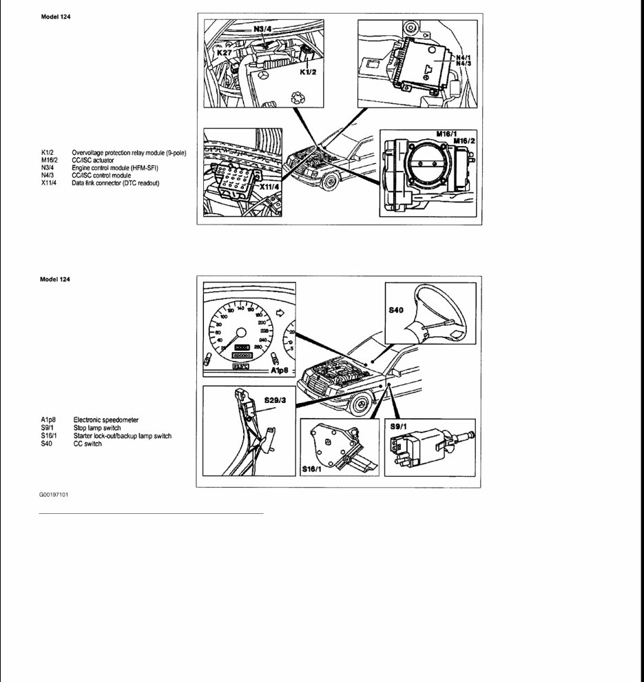
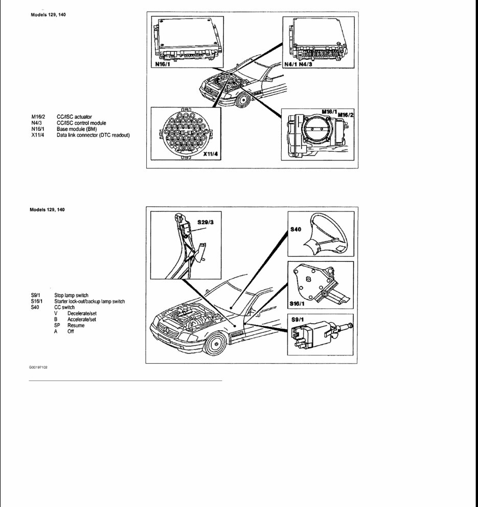
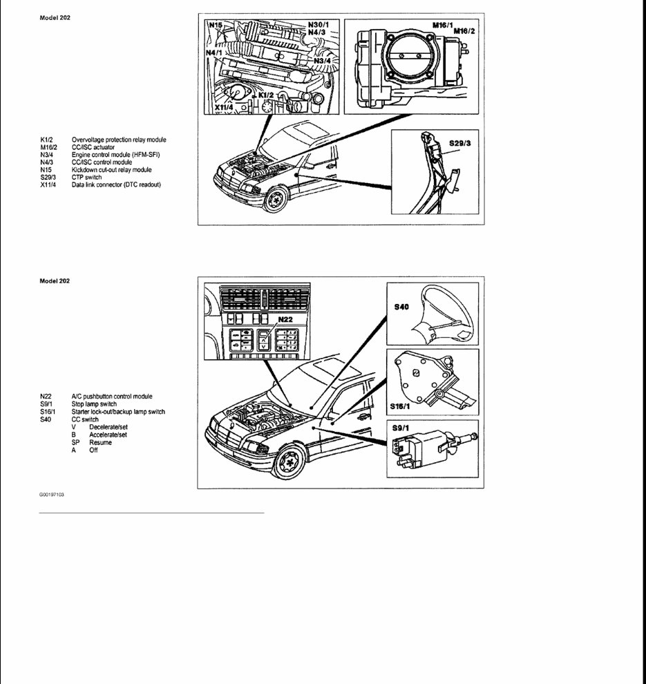
1993-96 ACCESSORIES & EQUIPMENT Cruise Control Systems IDENTIFICATION COMPONENT LOCATIONS ELECTRICAL SYSTEM TESTS COMPONENT LOCATIONS (SECTION 21) ELECTRICAL SYSTEM TESTS COMPONENT LOCATIONS (SECTION 21) WARNING: Vehicles are equipped with air bag supplemental restraint system. Before attempting ANY repairs involving steering column, instrument panel or related components, see SERVICE PRECAUTIONS and DISABLING & ACTIVATING AIR BAG SYSTEM in appropriate AIR BAG RESTRAINT SYSTEMS article. CAUTION: When battery is disconnected, vehicle computer and memory systems may lose memory data. Driveability problems may exist until computer systems have completed a relearn cycle. See COMPUTER RELEARN PROCEDURES article in GENERAL INFORMATION before disconnecting battery. CAUTION: Vehicles equipped with coded radios are susceptible to damage when battery is disconnected. Ensure ignition switch is in OFF position and radio is turned off before disconnecting battery. Have radio code available when disconnecting battery or removing radio. NOTE: For Mercedes-Benz model, chassis and engine identification, see MERCEDES - BENZ MODEL IDENTIFICATION . Component See Base Module - BM (N16/1) - Models 129 & 140 Fig. 2 A/C Pushbutton Control Module (N22) - Model 202 Fig. 3 CC Switch (S40) - Model 124 Fig. 1 CC Switch (S40) - Models 129 & 140 Fig. 2 CC Switch (S40) - Model 202 Fig. 3 CC/ISC Actuator (M16/2) - Model 124 Fig. 1 CC/ISC Actuator (M16/2) - Models 129 & 140 Fig. 2 CC/ISC Actuator (M16/2) - Model 202 Fig. 3 CC/ISC Control Module (N4/3) - Model 124 Fig. 1 CC/ISC Control Module (N4/3) - Models 129 & 140 Fig. 2
CC/ISC Control Module (N4/3) - Model 202 Fig. 3 CTP Switch (S29/3) - Model 202 Fig. 3 Data Link Connector - DTC Readout (X11/4) - Model 124 Fig. 1 Data Link Connector - DTC Readout (X11/4) - Models 129 & 140 Fig. 2 Data Link Connector - DTC Readout (X11/4) - Model 202 Fig. 3 Electronic Speedometer (A1p8) - Model 124 Fig. 1 Engine Control Module - HFM-SFI (N3/4) - Model 124 Fig. 1 Engine Control Module - HFM-SFI (N3/4) - Model 202 Fig. 3 Kickdown Cut-Out Relay Module (N15) - Model 202 Fig. 3 Overvoltage Protection Relay Module - 9 Pole (K1/2) - Model 124 Fig. 1 Overvoltage Protection Relay Module (K1/2) - Model 202 Fig. 3 Starter Lock-out/Backup Lamp Switch (S16/1) - Model 124 Fig. 1 Starter Lock-out/Backup Lamp Switch (S16/1) - Models 129 & 140 Fig. 2 Starter Lock-out/Backup Lamp Switch (S16/1) - Model 202 Fig. 3 Stop Lamp Switch (S9/1) - Model 124 Fig. 1 Stop Lamp Switch (S9/1) - Models 129 & 140 Fig. 2 Stop Lamp Switch (S9/1) - Model 202 Fig. 3
Fig. 1: Component Locations (Model 124) Courtesy of MERCEDES-BENZ OF NORTH AMERICA.
Fig. 2: Component Locations (Model 129 & 140) Courtesy of MERCEDES-BENZ OF NORTH AMERICA.
Fig. 3: Component Locations (Model 202) Courtesy of MERCEDES-BENZ OF NORTH AMERICA. PROGRAMMING ELECTRONIC TRACTION SYSTEM ADAPTATION NOTE: If the CC/ISC control module (N4/3) is replaced, or if a control module from another vehicle is temporarily installed, the ETS adaptation must be activated. Thereby allowing the CC/ISC control module to adapt to the vehicle configuration.
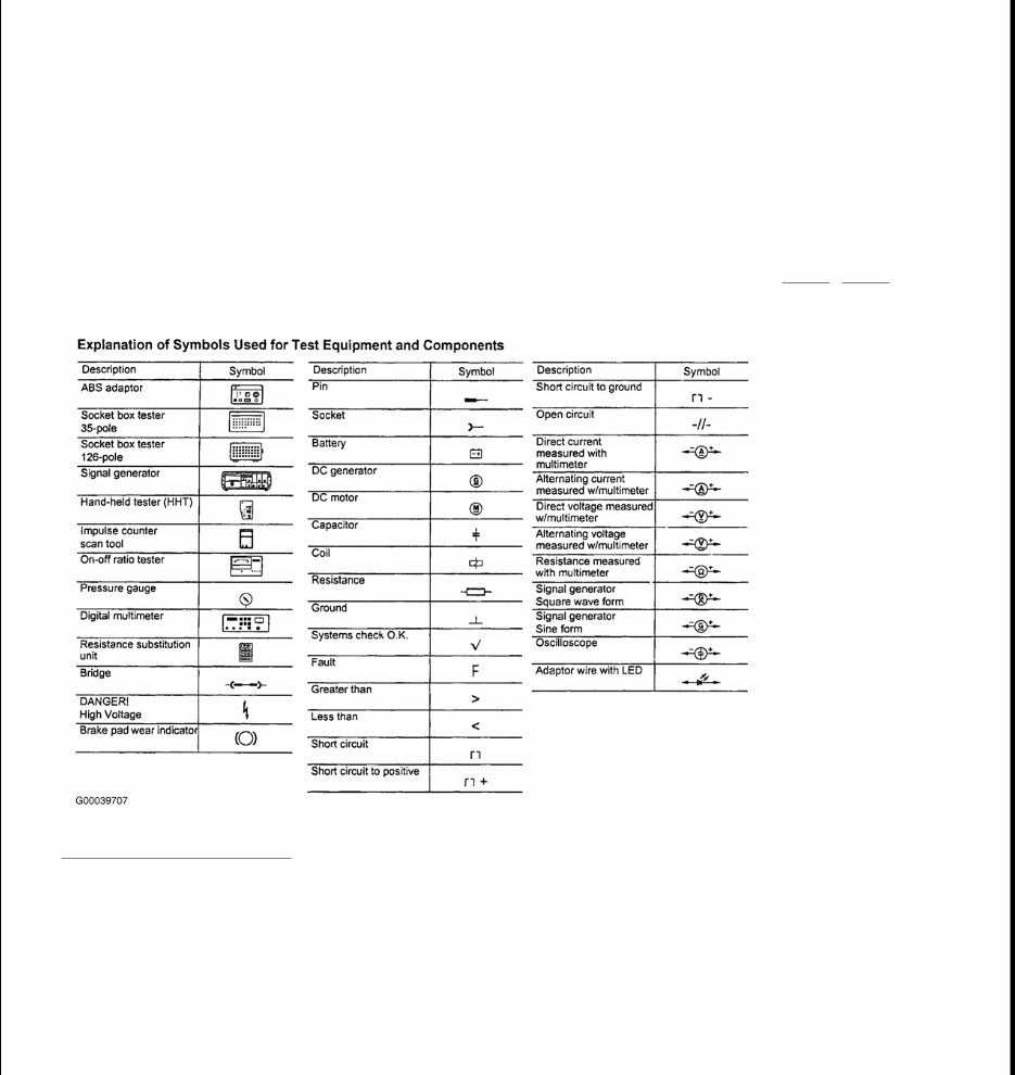
1. Turn ignition on. 2. Wait 3 seconds 3. Start engine. 4. Wait 7 seconds. 5. Turn ignition off 6. Turn ignition on. USING DIAGNOSTIC CHARTS Use following illustrations to understand diagnostic charts and identify symbols used. See Fig. 4 -Fig. 6 . Fig. 4: Identifying Symbols Courtesy of DAIMLERCHRYSLER CORPORATION
Get your hands on the 1994 Mercedes-Benz E320 Service & Repair Manual, a comprehensive guide for fixing vehicle issues using a Do-It-Yourself approach. This manual includes troubleshooting and replacement procedures recommended by the manufacturer, complete with step-by-step instructions, clear images, and exploded-view illustrations.
Whether you're a professional mechanic or a DIY enthusiast, you understand the importance of regular maintenance for your vehicle's durability. Over time, certain parts will wear out and require replacement, making a reliable repair manual indispensable. It equips you with the manufacturer's recommended troubleshooting charts and replacement procedures, enabling you to save on repairs, enhance your vehicle's reliability, and minimize visits to the repair shop.
This manual eliminates the hassle of searching through numerous pages for specific information and spares you from dealing with greasy, torn, or lost pages. Its digital format allows for easy accessibility, searchability, and portability, making it more convenient than a traditional bound manual. Additionally, you have the option to print a physical copy if preferred.
Format: .pdf
Printable: Yes
Language: English
Compatibility: Compatible with various electronic devices, including PC, Mac computers, Android and Apple smartphones, and tablets