

1999 Mazda B2500 Service & Repair Manual
What's Included?
Fast Download Speeds
Offline Viewing
Access Contents & Bookmarks
Full Search Facility
Print one or all pages of your manual

1999 STARTING & CHARGING SYSTEMS
Starters - Pickup
DESCRIPTION & OPERATION
A gear reduction starter with permanent magnets is used. An internal planetary gear reduction unit provides
increased cranking torque. The starting system includes a 6-pole, 4-brush starting motor with a solenoid-
actuated drive, battery, starter/ignition switch, transmission range sensor (A/T), clutch pedal position switch
(M/T), starter relay and associated circuitry.
If vehicle is equipped with anti-theft system, a starter interrupt relay is used to interrupt power between ignition
switch and transmission range sensor (A/T) or clutch pedal position switch (M/T) when anti-theft system is
activated.
TROUBLE SHOOTING
Check the following items before proceeding with testing:
z Check battery state of charge.
z Check cable connections at battery and starter motor.
z Ensure transmission is fully engaged in Park or Neutral position.
z Ensure clutch pedal is fully depressed.
z Check fuse No. 1 (50-amp) in power distribution box (in engine compartment).
z Check fuse No. 24 (7.5-amp) in instrument panel fuse box.
z On models equipped anti-theft system, ensure anti-theft system is operating properly (horn sounds, lights
flash, etc.) See appropriate ANTI-THEFT SYSTEMS article in ACCESSORIES & EQUIPMENT for
additional information.
ON-VEHICLE TESTING
ENGINE DOES NOT CRANK
1. Check battery condition and state of charge. If battery is okay, go to next step. If battery is not okay,
replace or charge battery as necessary.
2. Measure voltage between positive battery post and engine block were negative battery cable is connected
(on 4.0L engine, negative battery cable grounds to starter mounting stud). If battery voltage exists, go to
next step. If battery voltage does not exist, perform STARTER GROUND CIRCUIT TEST .
3. Measure voltage between positive battery post and starter motor case. If battery voltage exists, go to next
step. If battery voltage does not exist, clean starter motor mounting flange and ensure starter motor is
properly installed.
4. Turn ignition switch to LOCK position. Measure voltage at terminal "B" at starter solenoid. See Fig. 1 . If
battery voltage exists, go to next step. If battery voltage does not exist, perform VOLTAGE DROP
TEST . Replace positive battery cable if necessary.
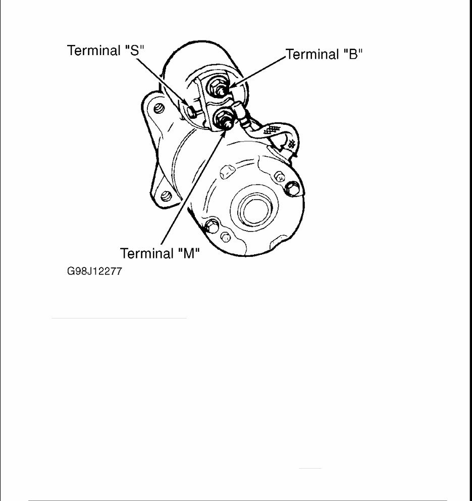
Fig. 1: Starter Solenoid Terminals
Courtesy of MAZDA MOTORS CORP.
5. Connect a remote starter switch between terminals "B" and "S" at starter solenoid. Engage remote starter
switch. If starter engages and engine cranks, go to next step. If starter motor does not engage,
repair/replace starter motor as necessary. If starter motor engages but engine does not crank, check for
engine mechanical failure (hydrostatic lock, seized, etc.). If mechanical failure does not exist,
repair/replace starter motor as necessary.
6. Disconnect Yellow/Light Blue wire from terminal "S" at starter solenoid. Measure voltage at
Yellow/Light Blue wire while turning ignition switch to START position. If battery voltage does not
exist, go to next step. If battery voltage exists, repair poor connection at terminal "S" at starter solenoid. If
connection is okay, replace starter solenoid.
7. Turn ignition switch to LOCK position. Remove starter relay. Starter relay is located in power
distribution box (in engine compartment). Measure voltage at terminal No. 85 (Tan/Red wire) at starter
relay socket while turning ignition switch to START position. See Fig. 2 . If battery voltage exists, go to
next step. If battery voltage does not exist, go to step 12 .
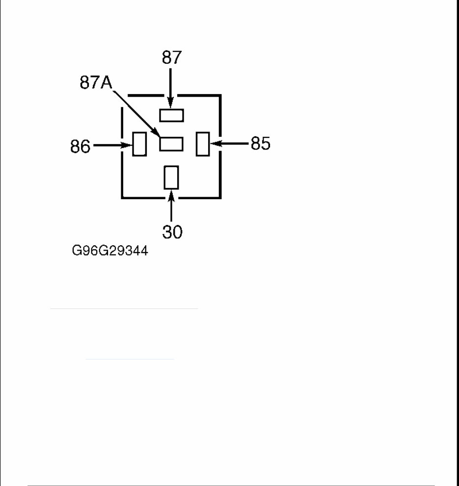
Fig. 2: Starter Relay Socket Terminals
Courtesy of MAZDA MOTORS CORP.
8. Turn ignition switch to LOCK position. Measure voltage at terminal No. 30 (Yellow wire) at starter relay
socket. If battery voltage exists, go to next step. If battery voltage does not exist, repair open in Yellow
wire. See WIRING DIAGRAMS .
9. Measure resistance between ground and terminal No. 86 (Black wire) at starter relay socket. If resistance
is 5 ohms or less, go to next step. If resistance is greater than 5 ohms, repair open in Black wire between
power distribution box and ground.
10. Ensure Yellow/Light Blue wire is disconnected from terminal "S" at starter. Measure resistance between
ground and terminal No. 87 (Yellow/Light Blue wire) at starter relay socket. If resistance is greater than
10,000 ohms, go to next step. If resistance is 10,000 ohms or less, repair short to ground in Yellow/Light
Blue wire between power distribution box and starter.
11. Measure resistance in Yellow/Light Blue wire between terminal No. 87 at starter relay socket and starter.
If resistance is greater than 5 ohms, repair open in Yellow/Light Blue wire between power distribution
box and starter. If resistance is 5 ohms or less, replace starter relay.

12. Disconnect Clutch Pedal Position (CPP) switch (M/T) or CPP jumper harness (A/T) connector (located
on clutch pedal bracket). Ensure anti-theft system is disabled (if equipped). Measure voltage at terminal
No. 6 (White/Pink wire) at CPP switch/jumper harness connector while turning ignition switch to START
position. See Fig. 3 . If battery voltage does not exist, go to next step. If battery voltage exists, go to step
20 .
13. Turn ignition switch to LOCK position. Remove and inspect fuse No. 24 (7.5-amp) in instrument panel
fuse box. If fuse is okay, go to next step. If fuse is blown, go to step 16 .
14. While turning ignition switch to START position, measure voltage at input side of fuse No. 24. If battery
voltage exists and vehicle is equipped anti-theft system, go to next step. If battery voltage exists and
vehicle is not equipped anti-theft system, repair open in White/Pink wire between instrument panel fuse
box and CPP switch/jumper harness connector. If battery voltage does not exist (with or without anti-theft
system), go to step 23 .
15. Disconnect Passive Anti-Theft System (PATS) module harness connector. Measure resistance between
ground and starter relay connector terminal No. 86 (Pink/Orange wire). If resistance is 50 ohms or less,
repair short to ground in Pink/Orange wire. If resistance is greater than 50 ohms, see appropriate ANT-
THEFT SYSTEMS article in ACCESSORIES & EQUIPMENT for diagnostic procedures.
16. Measure resistance between ground and terminal No. 6 (White/Pink wire) at CPP switch/jumper harness
connector. If resistance is greater than 10,000 ohms, go to next step. If resistance is 10,000 ohms or less,
repair short to ground in White/Pink wire between instrument panel fuse box and CPP switch/jumper
harness connector.
17. Remove starter relay from power distribution box in engine compartment. Measure resistance between
ground and terminal No. 5 (Pink wire) at CPP switch/jumper harness connector. If resistance is greater
than 10,000 ohms, repair intermittent short to ground. If resistance is 10,000 ohms or less and vehicle is
equipped with automatic transmission, go to next step. If resistance is 10,000 ohms or less and vehicle is
equipped with manual transmission, repair short to ground in Pink wire and/or Tan/Red wire between
starter relay and CPP switch/jumper harness connector.
18. Disconnect Transmission Range (TR) switch harness connector. Measure resistance between ground and
terminal No. 5 (Pink wire) at CPP switch/jumper harness connector. If resistance is greater than 10,000
ohms, go to next step. If resistance is 10,000 ohms or less, repair short to ground in Pink wire between
TR switch and CPP switch/jumper harness connector.
19. Measure resistance between ground and terminal No. 10 (Tan/Red wire) at TR switch harness connector.
See Fig. 4 . If resistance is greater than 10,000 ohms, go to next step. If resistance is 10,000 ohms or less,
repair short to ground in Tan/Red wire between TR switch and starter relay.
20. Remove starter relay from power distribution box in engine compartment. Measure resistance between
terminal No. 5 (Pink wire) at CPP switch/jumper harness connector and terminal No. 86 (Tan/Red wire)
at starter relay socket. See Fig. 2 and Fig. 3 . If resistance is 5 ohms or less, replace CPP switch/jumper
switch or jumper. If resistance is greater than 5 ohms and vehicle is equipped with automatic
transmission, go to next step. If resistance is greater than 5 ohms and vehicle is equipped with manual
transmission, repair open in Pink wire and/or Tan/Red wire between CPP switch/jumper harness
connector and starter relay.
21. Disconnect transmission range switch harness connector. Measure resistance in Pink wire between
terminal No. 5 at CPP switch/jumper harness connector 206 and terminal No. 12 at TR switch harness
NOTE: On vehicles equipped with automatic transmission, Clutch Pedal Position
(CPP) switch is substituted with a jumper harness.

connector. See Fig. 3 and Fig. 4 . If resistance is 5 ohms or less, go to next step. If resistance is greater
than 5 ohms, repair open in Pink wire between CPP switch/jumper harness connector and TR switch.
You're Reading a Preview
What's Included?
Fast Download Speeds
Offline Viewing
Access Contents & Bookmarks
Full Search Facility
Print one or all pages of your manual
$33.99
Viewed 26 Times Today


Secure transaction
What's Included?
Fast Download Speeds
Offline Viewing
Access Contents & Bookmarks
Full Search Facility
Print one or all pages of your manual
$33.99
- This repair manual provides comprehensive troubleshooting and replacement procedures, including step-by-step instructions, clear images, and exploded-view illustrations.
- It is useful for both professional mechanics and DIY enthusiasts for maintaining and repairing the 1999 Mazda B2500.
- Regular maintenance is essential for the vehicle's durability, and this manual offers the manufacturer's recommended troubleshooting charts and replacement procedures.
- It eliminates the hassle of searching through numerous pages and offers the convenience of digital access, allowing easy searching, bookmarking, and portability.
- It is available in English and compatible with various electronic devices, including PC, Mac, Android, and Apple devices, and requires Adobe Reader for access.
- For those who prefer a physical copy, the manual is also printable.


