

2007-2012 Mazda 3 (Mazda3/Mazdaspeed3) Service & Repair Manual
What's Included?
Fast Download Speeds
Offline Viewing
Access Contents & Bookmarks
Full Search Facility
Print one or all pages of your manual
2010
MaZDa3
MaZDaSPEED3
Workshop
Manual
FOREWORD
This manual contains on-vehicle service
and/or diagnosis procedures for the Mazda3/
Mazdaspeed3.
For proper repair and maintenance,
a thorough familiarization with this manual is
important, and it should always be kept in a
handy place for quick and easy reference.
All the contents of this manual, including
drawings and specifications, are the latest
available at the time of printing.
As modifications affecting repair or
maintenance occur, relevant information
supplementary to this volume will be made
available at Mazda dealers. This manual
should be kept up-to-date.
Mazda Motor Corporation reserves the right
to alter the specifications and contents of
this manual without obligation or advance
notice.
All rights reserved. No part of this book may
be reproduced or used in any form or by any
means, electronic or mechanical-including
photocopying and recording and the use of
any kind of information storage and retrieval
system-without permission in writing.
APPLICATION:
Mazda Motor Corporation
HIROSHIMA, JAPAN
This manual is applicable to vehicles
beginning with the Vehicle Identification
Numbers (VIN), and related materials
shown on the following page.
CONTENTS
Title
GENERAL INFORMATION
ENGINE
SUSPENSION
DRIVELINE/AXLE
BRAKES
TRANSMISSIONrrRANSAXLE
STEERING
HEATER, VENTILATION &
AIR CONDITIONING HVAC
RESTRAINTS
BODY & ACCESSORIES
ALPHABETICAL INDEX
© 2009 Mazda Motor Corporation
PRINTED IN U.S.A., APRIL 2009
Form No. 1930-1U-09D
Part No. 9999-95-0178-10
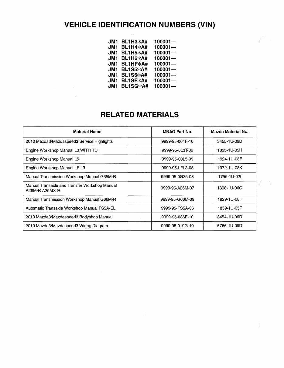
VEHICLE IDENTIFICATION NUMBERS (VIN)
JM1 BL1H3*A#
JM1 BL1H4*A#
JM1 BL1H5*A#
JM1 BL1H6*A#
JM1 BL1HF*A#
JM1 BL 1S5*A#
JM1 BL 1S6*A#
JM1 BL 1SF*A#
JM1 BL1SG*A#
100001-
100001-
100001-
100001-
100001-
100001-
100001-
100001-
100001-
RELATED MATERIALS
Material Name MNAO Part No.
2010 Mazda3/Mazdaspeed3 Service Highlights 9999-95-064F-10
Engine Workshop Manual L3 WITH TC 9999-95-0L3T-06
Engine Workshop Manual L5 9999-95-00L5-09
Engine Workshop Manual LF L3 9999-95-LFL3-08
Manual Transmission Workshop Manual G35M-R 9999-95-0G35-03
Manual Transaxle and Transfer Workshop Manual
9999-95-A26M-07
A26M-R A26MX-R
Manual Transmission Workshop Manual G66M-R 9999-95-G66M-09
Automatic Transaxle Workshop Manual FS5A-EL 9999-95-FS5A-06
2010 Mazda3/Mazdaspeed3 Bodyshop Manual 9999-95-036F-10
2010 Mazda3/Mazdaspeed3 Wiring Diagram 9999-95-019G-10
Mazda Material No.
3455-1 U-09D
1833-1 U-05H
1924-1 U-08F
1972-1 U-08K
1756-1 U-021
1898-1 U-06G
1929-1 U-08F
1859-1 U-05 F
3454-1 U-09D
5766-1 U-09D
WARNING
Servicing a vehicle can be dangerous. If you have not received
service-related training, the risks of injury, property damage, and
failure of servicing increase. The recommended servicing procedures
for the vehicle in this workshop manual were developed with
Mazda-trained technicians in mind. This manual may be useful to
non-Mazda trained technicians, but a technician with our
service-related training and experience will be at less risk when
performing service operations. However, all users of this manual are
expected to at least know general safety procedures.
This manual contains "Warnings" and "Cautions" applicable to risks
not normally encountered in a general technician's experience.
They should be followed to reduce the risk of injury and the risk
that improper service or repair may damage the vehicle or render it
unsafe. It is also important to understand that the "Warnings" and
"Cautions" are not exhaustive. It is impossible to warn of all
the hazardous consequences that might result from failure to follow
the procedures.
The procedures recommended and described in this manual are
effective methods of performing service and repair. Some require tools
specifically designed for a specific purpose. Persons using procedures
and tools which are not recommended by Mazda Motor Corporation
must satisfy themselves thoroughly that neither personal safety nor
safety of the vehicle will be jeopardized.
The contents of this manual, including drawings and specifications, are
the latest available at the time of printing, and Mazda Motor Corporation
reserves the right to change the vehicle designs and alter the contents
of this manual without notice and without incurring obligation.
Parts should be replaced with genuine Mazda replacement parts or
with parts which match the quality of genuine Mazda replacement
parts. Persons using replacement parts of lesser quality than that of
genuine Mazda replacement parts must satisfy themselves thoroughly
that neither personal safety nor safety of the vehicle will be
jeopardized.
Mazda Motor Corporation is not responsible for any problems which
may arise from the use of this manual. The cause of such problems
includes but is not limited to insufficient service-related training, use of
improper tools, use of replacement parts of lesser quality than that of
genuine Mazda replacement parts, or not being aware of any revision
of this manual.

, "
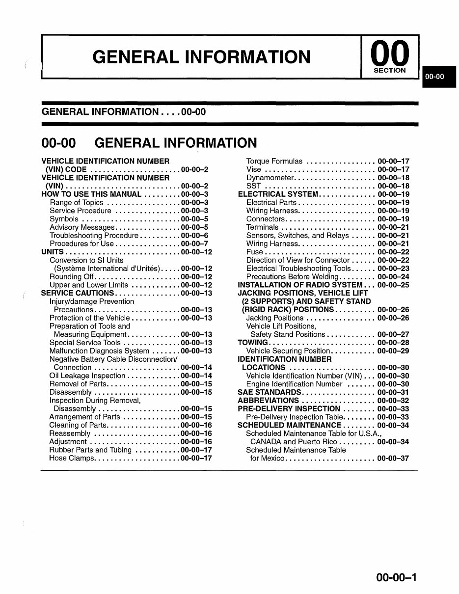
GENERAL INFORMATION
GENERAL INFORMATION .... 00-00
00-00 GENERAL INFORMATION
VEHICLE IDENTIFICATION NUMBER
(VIN) CODE ..................... . 00-00-2
VEHICLE IDENTIFICATION NUMBER
(VIN) ............................ 00-00-2
HOW TO USE THIS MANUAL . ....... . 00-00-3
Range of Topics ..• ....... • ....... 00-00-3
Service Procedure ............... . 00-00-3
Symbols ................ • ....... 00-00-5
Advisory Messages ........... • .... 00-00-5
Troubleshooting Procedure ......... . 00-00-6
Procedures for Use ............... . 00-00-7
UNITS . .......................... . 00-00-12
Conversion to SI Units
(Systeme International d'Unites) .... . 00-00-12
Rounding Off. ................... . 00-00-12
Upper and Lower Limits ........... . 00-00-12
SERVICE CAUTIONS . .............. . 00-00-13
Injury/damage Prevention
Precautions ............. • ...... . 00-00-13
Protection of the Vehicle ........... . 00-00-13
Preparation of Tools and
Measuring Equipment ............ . 00-00-13
Special Service Tools ...... •.• .... . 00-00-13
Malfunction Diagnosis System ...... . 00-00-13
Negative Battery Cable Disconnection/
Connection ............... • .... . 00-00-14
Oil Leakage Inspection ............ • 00-00-14
Removal of Parts ............ • .... . 00-00-15
Disassembly • ................... . 00-00-15
Inspection During Removal,
Disassembly ................... . 00-00-15
Arrangement of Parts ........ • .... • 00-00-15
Cleaning of Parts ................. . 00-00-16
Reassembly ..• ............ • .... • 00-00-16
Adjustment ..................... . 00-00-16
Rubber Parts and Tubing ...•.•...• . 00-00-17
Hose Clamps .................... . 00-00-17
Torque Formulas ........ • ........ 00-00-17
Vise ....... •...• .............. . 00-00-17
Dynamometer ........... •.• ...... 00-00-18
SST .......................... . 00-00-18
ELECTRICAL SySTEM .............. 00-00-19
Electrical Parts •..•...• .......... . 00-00-19
Wiring Harness ............ • ...... 00-00-19
Connectors •..• ...... • ........... 00-00-19
Terminals ..• .... • .............. . 00-00-21
Sensors, Switches, and Relays ...... 00-00-21
Wiring Harness •••• .............. . 00-00-21
Fuse ......... • ..... •...• ....... 00-00-22
Direction of View for Connector ...... 00-00-22
Electrical Troubleshooting Tools ...... 00-00-23
Precautions Before Welding ........ . 00-00-24
INSTALLATION OF RADIO SYSTEM . .. 00-00-25
JACKING POSITIONS, VEHICLE LIFT
(2 SUPPORTS) AND SAFETY STAND
(RIGID RACK) POSITIONS . ......... 00-00-26
Jacking Positions ................ . 00-00-26
Vehicle Lift Positions,
Safety Stand Positions ........... . 00-00-27
TOWING . ......................... 00-00-28
Vehicle Securing Position .......... . 00-00-29
IDENTIFICATION NUMBER
LOCATIONS ..................... 00-00-30
Vehicle Identification Number (VIN) .. . 00-00-30
Engine Identification Number ....... 00-00-30
SAE STANDARDS . ................ . 00-00-31
ABBREVIATIONS ................. . 00-00-32
PRE-DELIVERY INSPECTION ....... . 00-00-33
Pre-Delivery Inspection Table ....... . 00-00-33
SCHEDULED MAINTENANCE . ...... . 00-00-34
Scheduled Maintenance Table for U.S.A.,
CANADA and Puerto Rico ......... 00-00-34
Scheduled Maintenance Table
for Mexico ...................... 00-00-37
00-00-1
You're Reading a Preview
What's Included?
Fast Download Speeds
Offline Viewing
Access Contents & Bookmarks
Full Search Facility
Print one or all pages of your manual
$36.99
Viewed 60 Times Today


Secure transaction
What's Included?
Fast Download Speeds
Offline Viewing
Access Contents & Bookmarks
Full Search Facility
Print one or all pages of your manual
$36.99
This comprehensive service and repair manual for the 2007-2012 Mazda 3 (Mazda3/Mazdaspeed3) is an economical resource designed to ensure your vehicle’s optimal performance. The manual features detailed illustrations, diagrams, wiring schematics, specifications, and step-by-step instructions to guide both DIY enthusiasts and professional mechanics through a wide range of repair services.
- 2007-2012 Mazda 3 (Mazda3/Mazdaspeed3) Service & Repair Manual
- 2007-2012 Mazda 3 (Mazda3/Mazdaspeed3) Workshop Service & Repair Manual
- 2007-2012 Mazda 3 (Mazda3/Mazdaspeed3) Factory Service & Repair Manual
- 2007-2012 Mazda 3 (Mazda3/Mazdaspeed3) Repair Manual
- 2007-2012 Mazda 3 (Mazda3/Mazdaspeed3) Service Manual
- 2007-2012 Mazda 3 (Mazda3/Mazdaspeed3) Service Manual Repair
Product Details:
- File Format: PDF
- Language: English
- Specifications: Fully Printable
- Zoom IN/OUT: YES
- Delivery: Instant Access
- Requirements: Adobe Reader & Win
- Compatible: All Versions of Windows & Mac
The 2007-2012 Mazda 3 (Mazda3/Mazdaspeed3) Service & Repair Manual provides instant access to essential technical information for precise diagnostics and repairs, making it an indispensable resource for anyone working on these models.


