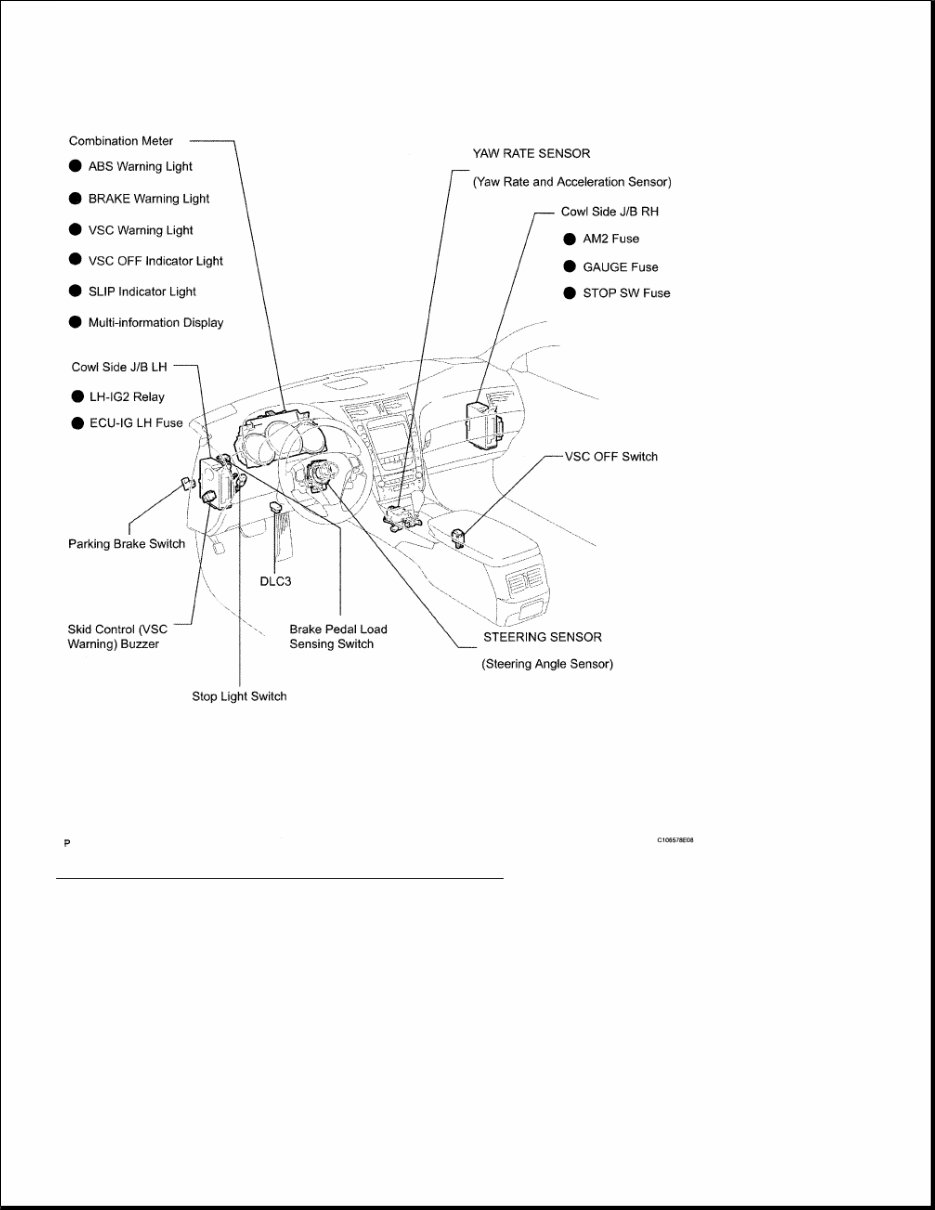
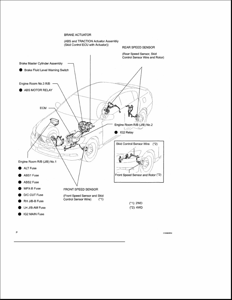
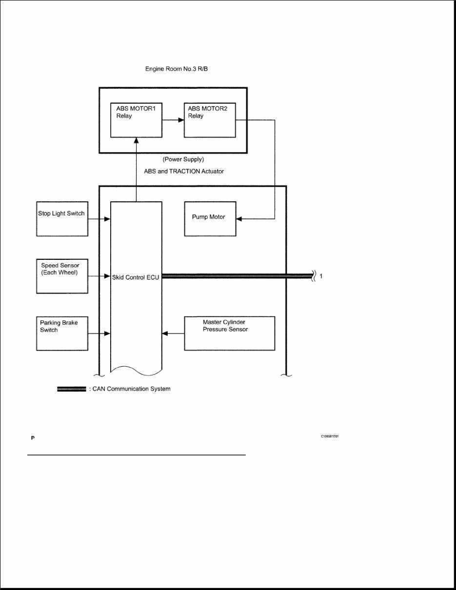
HVAC Air Conditioning - GS350/GS430 AIR CONDITIONING SYSTEM PRECAUTION SYSTEM REFERENCE PARTS LOCATION NOTE: When disconnecting the cable from the negative (-) battery terminal, initialize the following systems after the cable is reconnected. System Name See procedure Power Window Control System INITIALIZATION Intuitive Parking Assist System Variable Gear Ratio Steering System
Fig. 1: Identifying Air Conditioning Components (1 Of 3)
Fig. 2: Identifying Air Conditioning Components (2 Of 3)
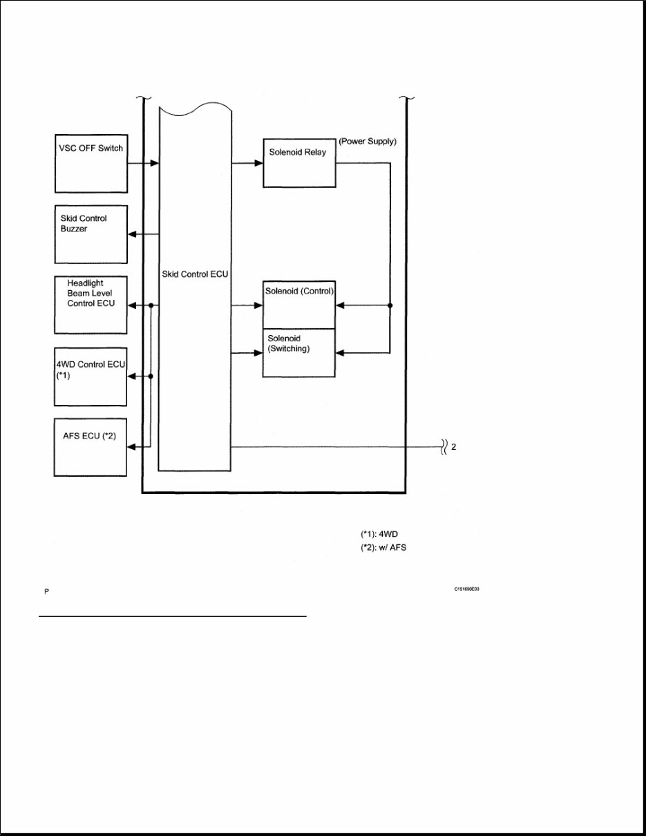
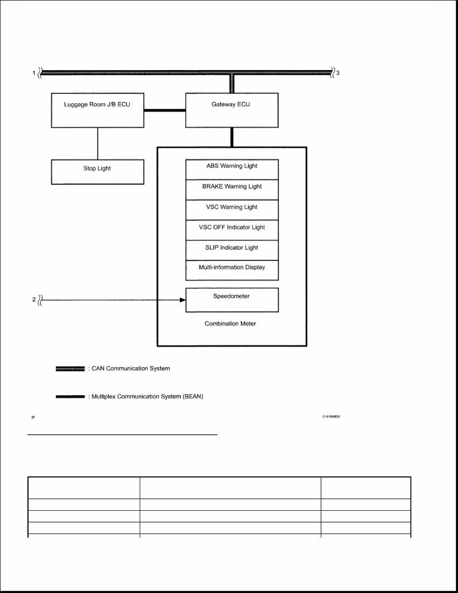
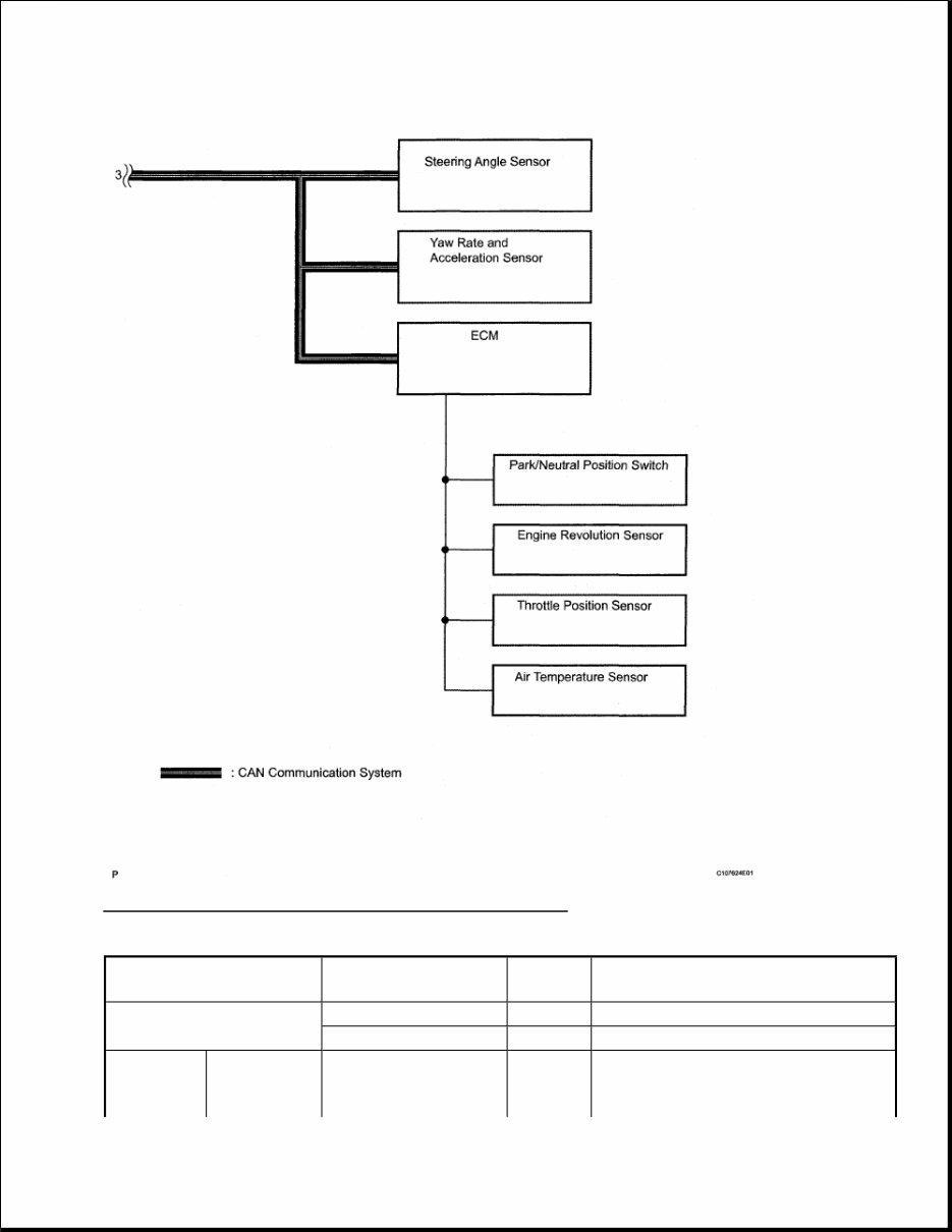
Fig. 3: Identifying Air Conditioning Components (3 Of 3) SYSTEM DIAGRAM
Fig. 4: Air Conditioning System Diagram (1 Of 2)
Fig. 5: Air Conditioning System Diagram (2 Of 2) Input signal to A/C amplifier: TRANSMITTING ECU SIGNALS Transmitting ECU (transmitter) Signals Communication Method Front Door RH ECU Mirror heater operation signal BEAN Front Door LH ECU Mirror heater operation signal BEAN ECM Heater relay signal CAN
Output signal to A/C amplifier: TRANSMITTING ECU SIGNALS SYSTEM DESCRIPTION 1. GENERAL a. The air conditioning system has the following features: In compliance with the temperature set with the temperature control switch, the A/C amplifier calculates the outlet temperature based on the input signals from various sensors. In addition, corrections in accordance with the signals from the room humidity sensor and the water temperature sensor are added to control the outlet air temperature. Controls the blower motor in accordance with the airflow volume that has been calculated by A/C amplifier based on the input signals from various sensors. Automatically changes the outlets in accordance with the outlet mode ratio that has been calculated by the A/C amplifier based on the input signals from various sensors. ECM Magnetic clutch signal CAN ECM Rear defogger relay operation signal CAN ECM Idle up signal CAN ECM A/C compressor signal CAN ECM Prohibition of charge signal CAN ECM Heater valve signal CAN ECM Pressure sensor signal CAN Distance Control ECU Ambient temperature signal CAN Multi-display Ambient temperature signal AVC-LAN Multi-display IND display signal AVC-LAN Multi-display Buzzer signal AVC-LAN Multi-display Driver and passenger side set temperature indication signal AVC-LAN Transmitting ECU (transmitter) Signals Communication Method Combination Meter Vehicle speed signal BEAN ECM Engine revolution speed signal CAN ECM Water temperature signal CAN ECM Ambient temperature signal CAN ECM A/C compressor lock signal CAN ECM A/C control cut signal CAN ECM A/C compressor control signal CAN Multi-display A/C operation signal AVC-LAN Multi-display Rear defogger operation signal AVC-LAN Multi-display Mirror heater operation signal AVC-LAN Multi-display Wiper deicer operation signal AVC-LAN
Automatically controls the air inlet control damper in accordance with the airflow volume that has been calculated by the A/C amplifier. Based on the signals from the ambient temperature sensor, this control calculates the outside temperature, which is then corrected in the air conditioning amplifier, and shown in the multi-information display in the combination meter. Turns the rear defogger and outside rear mirror heaters on for 15 minutes when the rear defogger switch is pressed. Turns them off if the switch is pressed while they are operating. The A/C amplifier automatically controls the air inlets based on the signals from the smog ventilation sensor. Checks the sensors in accordance with operation of the air conditioner switches. HINT: The smart connector has a built-in IC that enables communication with the A/C amplifier servomotor driving and position detection. The A/C amplifier equipped with the function of controlling the indicator lighting. 2. MODEL POSITION AND DAMPER OPERATION
Fig. 6: Identifying Model Position And Damper Operation CONTROL DAMPER OPERATION CHART Control Damper Control Position Damper Position Operation Air Inlet Control Damper FRESH B Brings in fresh air. RECIRC A Recirculates internal air. Air Mix Control Film Driver and Front Passenger MAX COOL to MAX HOT (TEMP. SETTING 18 to 32°C C, D, E Varies the mixture ratio of the fresh air and the recirculation air in order to regulate the temperature continuously
If you are in need of a repair manual for your 2007 Lexus GS350, look no further. Our accessible repair manual is the perfect resource for both professional mechanics and DIY enthusiasts. In the past, traditional paper repair manuals were the norm, but our digital format offers a more cost-effective and convenient alternative.
Whether you are tackling brake repairs, suspension component replacements, engine troubleshooting, or standard maintenance tasks, this repair manual provides comprehensive service information for your vehicle. It covers a wide range of areas including brakes, engine, suspension, steering, drivetrain, electrical systems, heating, and air conditioning.
By utilizing this manual, you can save a significant amount of money on vehicle maintenance and repairs. Mechanics often charge high fees for their services, making a DIY approach with the assistance of our 2007 Lexus GS350 repair manual a wise choice. The is compatible with Windows, Mac computers, smartphones, and tablets, ensuring ease of use for all users.