1986-1995 JEEP WRANGLER YJ Service and Repair Manual
What's Included?
Lifetime Access
Fast Download Speeds
Offline Viewing
Access Contents & Bookmarks
Full Search Facility
Print one or all pages of your manual
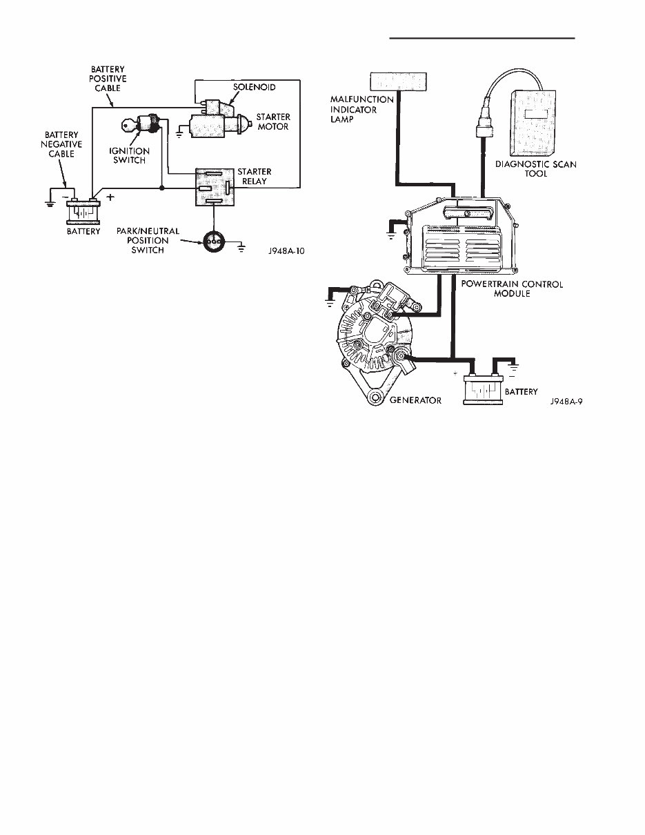
ELECTRICAL GROUP INDEX Group Group AUDIO SYSTEMS ........................ 8F BATTERY/STARTER/GENERATOR SERVICE .... 8B BATTERY/STARTING/CHARGING SYSTEMS DIAGNOSTICS ......................... 8A CHIME/BUZZER WARNING SYSTEMS ........ 8U HORNS ................................ 8G IGNITION SYSTEMS ...................... 8D INSTRUMENT PANEL AND GAUGES ......... 8E LAMPS ................................ 8L OVERHEAD CONSOLE .................... 8C POWER LOCKS .......................... 8P POWER MIRRORS ....................... 8T POWER SEATS .......................... 8R POWER WINDOWS ....................... 8S REAR WINDOW DEFOGGER ............... 8N RESTRAINT SYSTEMS ................... 8M TURN SIGNAL AND HAZARD WARNING SYSTEMS ............................. 8J VEHICLE SPEED CONTROL SYSTEM ......... 8H WIPER AND WASHER SYSTEMS ............ 8K XJ WIRING DIAGRAMS-LEFT HAND DRIVE . . . 8W XJ WIRING DIAGRAMS-RIGHT HAND DRIVE . 8W YJ WIRING DIAGRAMS .................. 8W BATTERY/STARTING/CHARGING SYSTEMS DIAGNOSTICS CONTENTS page page BATTERY ............................... 2 CHARGING SYSTEM ..................... 17 IGNITION-OFF DRAW .................... 10 SPECIFICATIONS ........................ 23 STARTING SYSTEM ...................... 11 USING ON-BOARD DIAGNOSTIC SYSTEM .... 22 GENERAL INFORMATION The battery, starting, and charging systems operate with one another; therefore, they must be tested as a complete system. In order for the vehicle to start and charge properly, all of the components involved in these systems must perform within specifications. Group 8A covers battery, starting (Fig. 1) and charging (Fig. 2) system diagnostic procedures. These procedures include the most basic conventional diag- nostic methods, to On-Board Diagnostics (OBD) built into the Powertrain Control Module (PCM). Use of an induction milliamp ammeter, volt/ohmmeter, battery charger, carbon pile rheostat (load tester), and 12- volt test lamp will be required. All OBD-sensed systems are monitored by the PCM. Each monitored circuit is assigned a Diagnos- tic Trouble Code (DTC). The PCM will store a DTC in electronic memory for any failure it detects. See Us- ing On-Board Diagnostic System in this group for more information. J ELECTRICAL 8A - 1
BATTERY GENERAL INFORMATION The storage battery is a device used to store elec- trical energy potential in a chemical form. When an electrical load is applied to the battery terminals, an electrochemical reaction occurs within the battery. This reaction causes the battery to discharge electri- cal current. The battery is made up of 6 individual cells that are connected in series. Each cell contains positively charged plate groups made of lead oxide, and nega- tively charged plate groups made of sponge lead. These dissimilar metal plates are submerged in a sulfuric acid and water solution called electrolyte. As the battery discharges, a gradual chemical change takes place within each cell. The sulfuric acid in the electrolyte combines with the plate materials, causing both plates to change to lead sulfate. At the same time, oxygen from the positive plate material combines with hydrogen from the sulfuric acid, caus- ing the electrolyte to become mainly water. The chemical changes within the battery are caused by movement of excess or free electrons be- tween the positive and negative plate groups. This movement of electrons produces a flow of electrical current through the load device attached to the bat- tery terminals. As the plate materials become more similar chem- ically, and the electrolyte becomes less acid, the volt- age potential of each cell is reduced. However, by charging the battery with a voltage higher than that of the battery, the process is reversed. Charging the battery gradually changes the sul- fated lead plates back into sponge lead and lead ox- ide, and the water back into sulfuric acid. This action restores the difference in electron charges deposited on the plates, and the voltage potential of the battery cells. For a battery to remain useful, it must be able to produce high-amperage current over an extended pe- riod. A battery must also be able to accept a charge, so that its voltage potential may be restored. In addition to producing and storing electrical en- ergy, the battery serves as a capacitor or voltage sta- bilizer for the vehicle electrical system. It absorbs abnormal or transient voltages caused by switching of any of the vehicle’s electrical components. The battery is vented to release excess gas that is created when the battery is being charged or dis- Fig. 1 Starting System Components (Typical) Fig. 2 Charging System Components (Typical) 8A - 2 BATTERY/STARTING/CHARGING SYSTEMS DIAGNOSTICS J
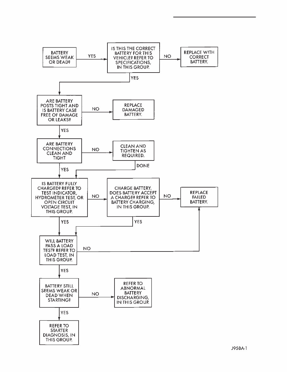
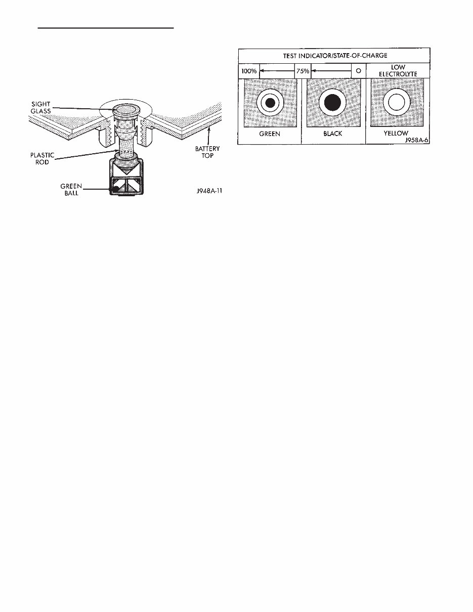
charged. However, even with these vents, hydrogen gas can collect in or around the battery. If hydrogen gas is exposed to flame or sparks, it can ignite. If the electrolyte level is low, the battery could arc internally and explode. If the battery is equipped with removable cell caps, add distilled water when- ever the electrolyte level is below the top of the plates. If the battery cell caps cannot be removed, the battery must be replaced when the electrolyte level is low. WARNING: DO NOT ATTEMPT TO ASSIST BOOST, CHARGE, OR TEST BATTERY WHEN ELECTRO- LYTE LEVEL IS BELOW THE TOP OF THE PLATES. PERSONAL INJURY MAY OCCUR. BATTERY RATINGS Currently, there are 2 commonly accepted methods for rating and comparing battery performance. These ratings are called Cold Cranking Amperage (CCA), and Reserve Capacity (RC). Be certain that a replace- ment battery has CCA and RC ratings that equal or exceed the original equipment specification for the vehicle being serviced. See Battery Classifications and Ratings charts in Specifications at the back of this group. COLD CRANKING AMPERAGE The Cold Cranking Amperage (CCA) rating speci- fies how much current (in amperes) the battery can deliver for 30 seconds at -17.7°C (0°F). Terminal volt- age must not fall below 7.2 volts during or after the 30 second discharge. The CCA required is generally higher as engine displacement increases, depending also upon the starter current draw requirements. RESERVE CAPACITY The Reserve Capacity (RC) rating specifies the time (in minutes) it takes for battery terminal volt- age to fall below 10.2 volts at a discharge rate of 25 amps. RC is determined with the battery fully- charged at 26.7°C (80°F). This rating estimates how long the battery might last after a charging system failure, under minimum electrical load. DIAGNOSIS The battery must be completely charged and the top, posts, and terminal clamps should be properly cleaned before diagnostic procedures are performed. Refer to Group 8B - Battery/Starter/Generator Ser- vice for more information. The condition of a battery is determined by two cri- teria: (1) State-Of-Charge This can be determined by viewing the built-in test indicator, by checking spe- cific gravity of the electrolyte (hydrometer test), or by checking battery voltage (open circuit voltage test). (2) Cranking Capacity This can be determined by performing a battery load test, which measures the ability of the battery to supply high-amperage current. If the battery has a built-in test indicator, use this test first. If it has no test indicator, but has remov- able cell caps, perform the hydrometer test first. If cell caps are not removable, or a hydrometer is not available, perform the open circuit voltage test first. The battery must be charged before proceeding with a load test if: • the built-in test indicator has a black or dark color visible • the temperature corrected specific gravity is less than 1.235 • the open circuit voltage is less than 12.4 volts. A battery that will not accept a charge is faulty and further testing is not required. A battery that is fully-charged, but does not pass the load test is faulty and must be replaced. Completely discharged batteries may take several hours to accept a charge. See Charging Completely Discharged Battery. A battery is fully-charged when: • all cells are gassing freely during charging • a green color is visible in the sight glass of the built-in test indicator • three corrected specific gravity tests, taken at 1-hour intervals, indicate no increase in specific grav- ity • open circuit voltage is 12.4 volts or greater. ABNORMAL BATTERY DISCHARGING Any of the following conditions can result in abnor- mal battery discharging: (1) Corroded battery posts and terminals. (2) Loose or worn generator drive belt. (3) Electrical loads that exceed the output of the charging system, possibly due to equipment installed after manufacture or repeated short trip use. (4) Slow driving speeds (heavy traffic conditions) or prolonged idling with high-amperage draw systems in use. (5) Faulty circuit or component causing excessive ignition-off draw. See Ignition-Off Draw in this group for diagnosis. (6) Faulty charging system. (7) Faulty or incorrect battery. BUILT-IN TEST INDICATOR A test indicator (hydrometer) built into the top of the battery case, provides visual information for bat- tery testing (Fig. 1). It is important when using the test indicator that the battery be level and have a clean sight glass to see correct indications. Additional light may be required to view indicator. J BATTERY/STARTING/CHARGING SYSTEMS DIAGNOSTICS 8A - 3
BATTERY DIAGNOSIS 8A - 4 BATTERY/STARTING/CHARGING SYSTEMS DIAGNOSTICS J
WARNING: DO NOT USE OPEN FLAME AS A SOURCE OF ADDITIONAL LIGHT FOR VIEWING TEST INDICATOR. EXPLOSIVE HYDROGEN GAS MAY BE PRESENT IN THE AREA SURROUNDING BATTERY. Like a hydrometer, the built-in test indicator mea- sures the specific gravity of the electrolyte. Specific gravity will indicate battery state-of-charge. How- ever, the test indicator will not indicate cranking ca- pacity of the battery. See Load Test in this group for more information. Look into the sight glass and note the color of the indicator (Fig. 2). Refer to the following description, as the color indicates: GREEN—indicates 75% to 100% state-of-charge. The battery is adequately charged for further test- ing or return to use. If the vehicle will not crank for a minimum of 15 seconds with a fully-charged bat- tery, perform Load Test. BLACK OR DARK—indicates 0% to 75% state-of- charge. The battery is inadequately charged and must be charged until green indicator (Fig. 2) is visible in sight glass (12.4 volts or more) before the battery is tested further or returned to use. See Abnormal Bat- tery Discharging in this group to diagnose cause of discharged condition. YELLOW OR BRIGHT—indicates low electrolyte level. The electrolyte level in the battery is below test in- dicator (Fig. 2). A maintenance-free battery with non- removable cell caps must be replaced if electrolyte level is low. Water can be added to a low-mainte- nance battery with removable cell caps. A low electro- lyte level may be caused by an over-charging condition. See Charging System in this group to di- agnose an over-charging condition. WARNING: DO NOT ATTEMPT TO CHARGE, TEST, OR ASSIST BOOST BATTERY WHEN YELLOW OR BRIGHT COLOR IS VISIBLE IN SIGHT GLASS OF TEST INDICATOR. LOW ELECTROLYTE LEVEL CAN ALLOW BATTERY TO ARC INTERNALLY AND EX- PLODE. PERSONAL INJURY MAY OCCUR. HYDROMETER TEST The hydrometer test reveals the battery state-of- charge by measuring the specific gravity of the elec- trolyte. This test cannot be performed on batteries with non-removable cell caps. If battery has non-re- movable cell caps, see Built-In Test Indicator or Open Circuit Voltage Test. Specific gravity is a comparison of the density of the electrolyte to the density of pure water. Pure wa- ter has a specific gravity of 1.000, and sulfuric acid has a specific gravity of 1.835. Sulfuric acid makes up approximately 35% of the electrolyte by weight, or 24% by volume. In a fully-charged battery the electrolyte will have a temperature corrected specific gravity of 1.260 to 1.290. However, a specific gravity of 1.235 or above is satisfactory for battery load testing and/or return to service. Before testing, visually inspect battery for any damage (cracked case or cover, loose posts, etc.) that would cause the battery to be faulty. Then remove cell caps and check electrolyte level. Add distilled wa- ter if electrolyte level is below the top of the battery plates. To use the hydrometer correctly, hold it with the top surface of the electrolyte at eye level. Refer to the hydrometer manufacturer’s instructions for correct use of hydrometer. Remove only enough electrolyte from the battery so the float is off the bottom of the hydrometer barrel with pressure on the bulb re- leased. Exercise care when inserting the tip of the hydrom- eter into a cell to avoid damaging the plate separa- tors. Damaged plate separators can cause premature battery failure. Hydrometer floats are generally calibrated to indi- cate the specific gravity correctly only at 26.7°C (80°F). When testing the specific gravity at any other temperature, a correction factor is required. The correction factor is approximately a specific gravity value of 0.004, referred to as 4 points of spe- cific gravity. For each 5.5°C above 26.7°C (10°F above 80°F), add 4 points. For each 5.5°C below 26.7°C (10°F below 80°F), subtract 4 points. Always correct Fig. 1 Built-In Test Indicator Fig. 2 Built-In Test Indicator Sight Glass J BATTERY/STARTING/CHARGING SYSTEMS DIAGNOSTICS 8A - 5
The 1986-1995 JEEP WRANGLER YJ Service and Repair Manual is a comprehensive guide that provides detailed information and step-by-step instructions to help owners and mechanics perform maintenance, service, and repairs on their JEEP WRANGLER YJ vehicles from 1986 to 1995.
This manual covers various models of the JEEP WRANGLER YJ, including:
1986 JEEP WRANGLER YJ
1987 JEEP WRANGLER YJ
1988 JEEP WRANGLER YJ
1989 JEEP WRANGLER YJ
1990 JEEP WRANGLER YJ
1991 JEEP WRANGLER YJ
1992 JEEP WRANGLER YJ
1993 JEEP WRANGLER YJ
1994 JEEP WRANGLER YJ
1995 JEEP WRANGLER YJ
Whether you need to perform routine maintenance tasks, troubleshoot electrical and mechanical issues, or undertake major repairs, this service and repair manual will be your go-to resource. It is packed with detailed diagrams, illustrations, and photographs to assist you in understanding the procedures and performing them correctly.
With this manual, you can save time and money by avoiding costly visits to service centers and mechanics. It empowers you to maintain and repair your JEEP WRANGLER YJ with confidence and ensure its optimal performance and longevity.
Recently Viewed
5,521,897Happy Clients
2,594,462eManuals
1,120,453Trusted Sellers
15Years in Business
Price:
Actual Price:
1986-1995 JEEP WRANGLER YJ Service and Repair Manual