Jeep AX 15 Transmission Service & workshop Repair Manual
What's Included?
Lifetime Access
Fast Download Speeds
Online & Offline Access
Access PDF Contents & Bookmarks
Full Search Facility
Print one or all pages of your manual
AX 15 MANUAL TRANSMISSION INDEX page page General Information ....................... 32 Service Diagnosis ........................ 33 Transmission Assembly and Adjustment ....... 51 Transmission Disassembly and Overhaul ....... 36 Transmission Gear Ratios .................. 33 Transmission Identification .................. 32 Transmission Installation—AX 15 ............. 35 Transmission Lubricant .................... 33 Transmission Removal—AX 15 .............. 34 Transmission Shift Pattern .................. 33 Transmission Switch and Plug Locations ....... 33 GENERAL INFORMATION The AX 15 is a 5-speed, synchromesh, manual transmission. Fifth gear is an overdrive range with a ratio of 0.79:1. The shift mechanism is integral and mounted in the shift tower portion of the adapter housing (Fig. 1). An adapter housing is used to attach the transmis- sion to the transfer case on 4-wheel drive models. A standard extension housing is used on 2-wheel drive models. The AX 15 is used in XJ and YJ models with a 4.0L engine. The AX 15 is designed for use with ei- ther two-wheel drive or four-wheel drive applica- tions. TRANSMISSION IDENTIFICATION The AX 15 identification code numbers are on the bottom surface of the transmission gear case (Fig. 2). The first number is year of manufacture. The sec- ond and third numbers indicate month of manufac- ture. The next series of numbers is the transmission serial number. Fig. 1 AX 15 Manual Transmission Fig. 2 Identification Code Number Location 21 - 32 AX 15 MANUAL TRANSMISSION J
TRANSMISSION SHIFT PATTERN The AX 15 shift pattern is shown in Figure 3. First and second and third and fourth gear ranges are in line for improved shifting. Fifth and reverse gear ranges are also in line at the extreme right of the pattern (Fig. 3). The AX 15 is equipped with a reverse lockout mechanism. The shift lever must be moved through the Neutral detent before making a shift to reverse. TRANSMISSION LUBRICANT Recommended lubricant for AX 15 transmissions is Mopar 75W-90, API Grade GL-5 gear lubricant, or equivalent. Correct lubricant refill or top-off level is to the bot- tom edge of the fill plug hole. Lubricant capacity is: • 3.10 liters (3.27 qts.) in 4-wheel drive models. • 3.15 liters (3.32 qts.) in 2-wheel drive models. TRANSMISSION SWITCH AND PLUG LOCATIONS The fill plug is at the driver side of the gear case (Fig. 4). The drain plug and backup light switch are on the passenger side of the gear case (Fig. 5). TRANSMISSION GEAR RATIOS The transmission gear ratios are as follows: First gear - 3.83:1 Second gear - 2.33:1 Third gear - 1.44:1 Fourth gear - 1.00:1 Fifth gear - 0.79:1 Reverse - 4.22:1 SERVICE DIAGNOSIS LOW LUBRICANT LEVEL A low transmission lubricant level is generally the result of a leak, inadequate lubricant fill, or an in- correct lubricant level check. Leaks can occur at the mating surfaces of the gear case, intermediate plate and adapter or extension housing, or from the front/rear seals. A suspected leak could also be the result of an overfill condition. Leaks at the rear of the extension or adapter hous- ing will be from the housing oil seals. Leaks at com- ponent mating surfaces will probably be the result of inadequate sealer, gaps in the sealer, incorrect bolt tightening, or use of a non-recommended sealer. A leak at the front of the transmission will be from either the front bearing retainer or retainer seal. Lu- bricant may be seen dripping from the clutch hous- ing after extended operation. If the leak is severe, it may also contaminate the clutch disc causing slip, grab and chatter. Transmissions filled from air or electrically pow- ered lubricant containers can be underfilled. This generally happens when the container delivery mech- anism is improperly calibrated. Always check the lu- bricant level after filling to avoid an under fill condition. A correct lubricant level check can only be made when the vehicle is level; use a drive-on hoist to en- sure this. Also allow the lubricant to settle for a Fig. 3 AX 15 Shift Pattern Fig. 4 Fill Plug Location Fig. 5 Drain Plug And Backup Light Switch Location J AX 15 MANUAL TRANSMISSION 21 - 33
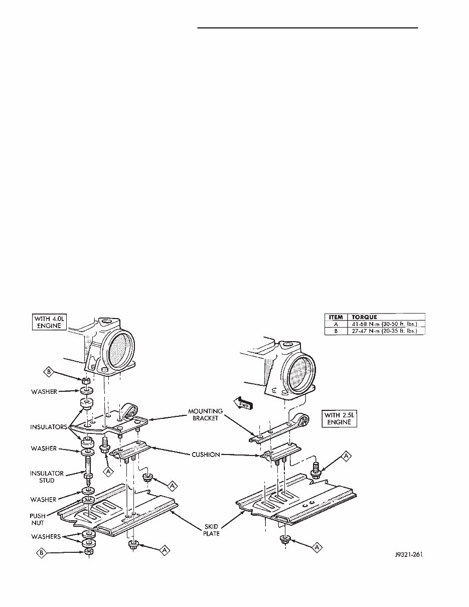
minute or so before checking. These recommenda- tions will ensure an accurate check and avoid an un- der-or-overfill condition. HARD SHIFTING Hard shifting is usually caused by a low lubricant level, improper or contaminated lubricants, compo- nent damage, incorrect clutch adjustment, or by a damaged clutch pressure plate or disc. Substantial lubricant leaks can result in gear, shift rail, synchro and bearing damage. If a leak goes un- detected for an extended period, the first indications of a problem are usually hard shifting and noise. Incorrect or contaminated lubricants can also con- tribute to hard shifting. The consequence of using non-recommended lubricants is noise, excessive wear, internal bind and hard shifting. Improper clutch release is a frequent cause of hard shifting. Incorrect adjustment or a worn, damaged pressure plate or disc can cause incorrect release. If the clutch problem is advanced, gear clash during shifts can result. Worn or damaged synchro rings can cause gear clash when shifting into any forward gear. In some new or rebuilt transmissions, new synchro rings may tend to stick slightly causing hard or noisy shifts. In most cases, this condition will decline as the rings wear-in. TRANSMISSION NOISE Most manual transmissions make some noise dur- ing normal operation. Rotating gears can generate a mild whine that may only be audible at extreme speeds. Severe, obviously audible transmission noise is generally the result of a lubricant problem. Insuffi- cient, improper, or contaminated lubricant can pro- mote rapid wear of gears, synchros, shift rails, forks and bearings. The overheating caused by a lubricant problem, can also lead to gear breakage. TRANSMISSION REMOVAL—AX 15 (1) Shift transmission into first or third gear. (2) Raise vehicle on a hoist. (3) Disconnect necessary exhaust system compo- nents. (4) Support transmission with adjustable jack stand. (5) Disconnect rear cushion and mounting bracket from transmission, or transfer case (Fig. 1). (6) On XJ, remove rear crossmember. On YJ, re- move skid plate (Fig. 1). (7) Disconnect transmission shift linkage, speed- ometer cable, transfer case vacuum lines and clutch hydraulic lines. (8) Lower transmission-transfer case assembly no more than 7.6 cm (3 in.) for access to shift lever. Fig. 1 Rear Mount Components (YJ Shown) 21 - 34 AX 15 MANUAL TRANSMISSION J
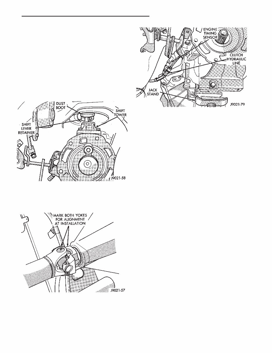
(9) Reach up and around transmission case and unseat shift lever dust boot from transmission shift tower (Fig. 2). Move boot upward on shift lever for access to lever retainer. (10) Disengage shift lever as follows: (a) Reach up and around transmission case and press shift lever retainer downward with your fin- gers. (b) Turn retainer counterclockwise to release it. (c) Lift lever and retainer out of shift tower (Fig. 2). It is not necessary to remove shift lever from floorpan boot. Simply leave lever in place for later installation. (11) Mark front and rear propeller shafts for in- stallation alignment (Fig. 3). Then remove both shafts. (12) Remove crankshaft position/engine timing sen- sor (Fig. 4). (13) Disconnect transmission and transfer case vent hoses. (14) Remove slave cylinder from clutch housing. (15) Support transmission-transfer case assembly with transmission jack. Secure assembly to jack with safety chains. (16) Reposition adjustable jack stand under engine. Be sure to place wood block between jack and oil pan. (17) Remove clutch housing brace rod. (18) Remove clutch housing-to-engine bolts and re- move transmission-transfer case assembly. (19) Remove bolts attaching transmission to trans- fer case and separate components. (20) Remove release bearing, fork and retainer clip. (21) Remove clutch housing from transmission. TRANSMISSION INSTALLATION—AX 15 (1) Install clutch housing on transmission. Tighten housing bolts to 37 Nzm (27 ft-lbs) torque. (2) Lubricate contact surfaces of release fork, lever and pivot ball stud. Then install bearing, fork and clip in clutch housing. (3) Mount transmission on transmission jack. Se- cure transmission with safety chains. (4) Lightly lubricate pilot bearing and transmis- sion input shaft splines with Mopar high tempera- ture grease. (5) Align transmission input shaft and clutch disc splines and install transmission. (6) Install and tighten clutch housing-to-engine bolts to 38 Nzm (28 ft. lbs.) torque. Be sure housing is properly seated on engine before tightening bolts. (7) Lower transmission no more than 7.6 cm (3 in.) for access to the shift tower. (8) Reach up and around the transmission and in- sert shift lever in shift tower. Press lever retainer downward and turn it clockwise to lock it in place. Then install lever dust boot on shift tower. (9) Connect engine timing sensor. Fig. 2 Removing/Installing Shift Lever Fig. 3 Marking Propeller Shaft And Axle Yoke Fig. 4 Timing Sensor Location J AX 15 MANUAL TRANSMISSION 21 - 35
(10) Remove jack from under transmission and mount transfer case on jack. (11) Align transfer case and transmission shafts and install transfer case. Tighten transfer case-to- transmission nuts/bolts to 35 Nzm (26 ft. lbs.) torque. (12) Move jack stand from under engine and repo- sition it under transmission. Then remove transmis- sion jack. (13) Connect transfer case vacuum hoses and link- age. Check and adjust linkage if necessary. (14) Connect transmission and transfer case vent hoses and backup light switch wires. (15) Install clutch sleeve cylinder. (16) Connect vehicle speed sensor and wires. (17) On XJ, install rear crossmember and attach cushion and bracket. Tighten crossmember-to-frame bolts to 41 Nzm (30 ft. lbs.) torque. Tighten transmis- sion-to-rear cushion and bracket bolts/nuts to 45 Nzm (33 ft. lbs.) torque. (18) On YJ, install rear cushion and bracket and skid plate. Tighten attaching bolts/nuts to indicated torque (Fig. 1). (19) Align and install front/rear propeller shafts. Tighten shaft U-joint clamp bolts to 19 Nzm (170 in. lbs.) torque. (20) On XJ, install skid plate if removed. Tighten bolts to 42 Nzm (31 ft. lbs.) torque. Tighten stud nuts to 17 Nzm (150 in. lbs.) torque. (21) Top off transmission and transfer lubricant levels. (22) Remove supports and lower vehicle. TRANSMISSION DISASSEMBLY AND OVERHAUL ADAPTER/EXTENSION HOUSING REMOVAL (1) Remove release bearing, fork, retainer clip and clutch housing from transmission. Also remove shift lever if not previously removed. (2) On 2-wheel drive models, remove extension housing seal (Fig. 1). (3) Remove shift tower bolts and remove tower from adapter or extension housing (Fig. 2). (4) Remove gasket from shift tower (Fig. 3). (5) Remove shift arm retainer bolt (Fig. 4). Fig. 1 Removing Extension Housing Seal Fig. 2 Shift Tower Removal/Installation Fig. 3 Shift Tower Gasket Removal/Installation Fig. 4 Shift Arm Retainer Bolt Removal/Installation 21 - 36 AX 15 MANUAL TRANSMISSION J
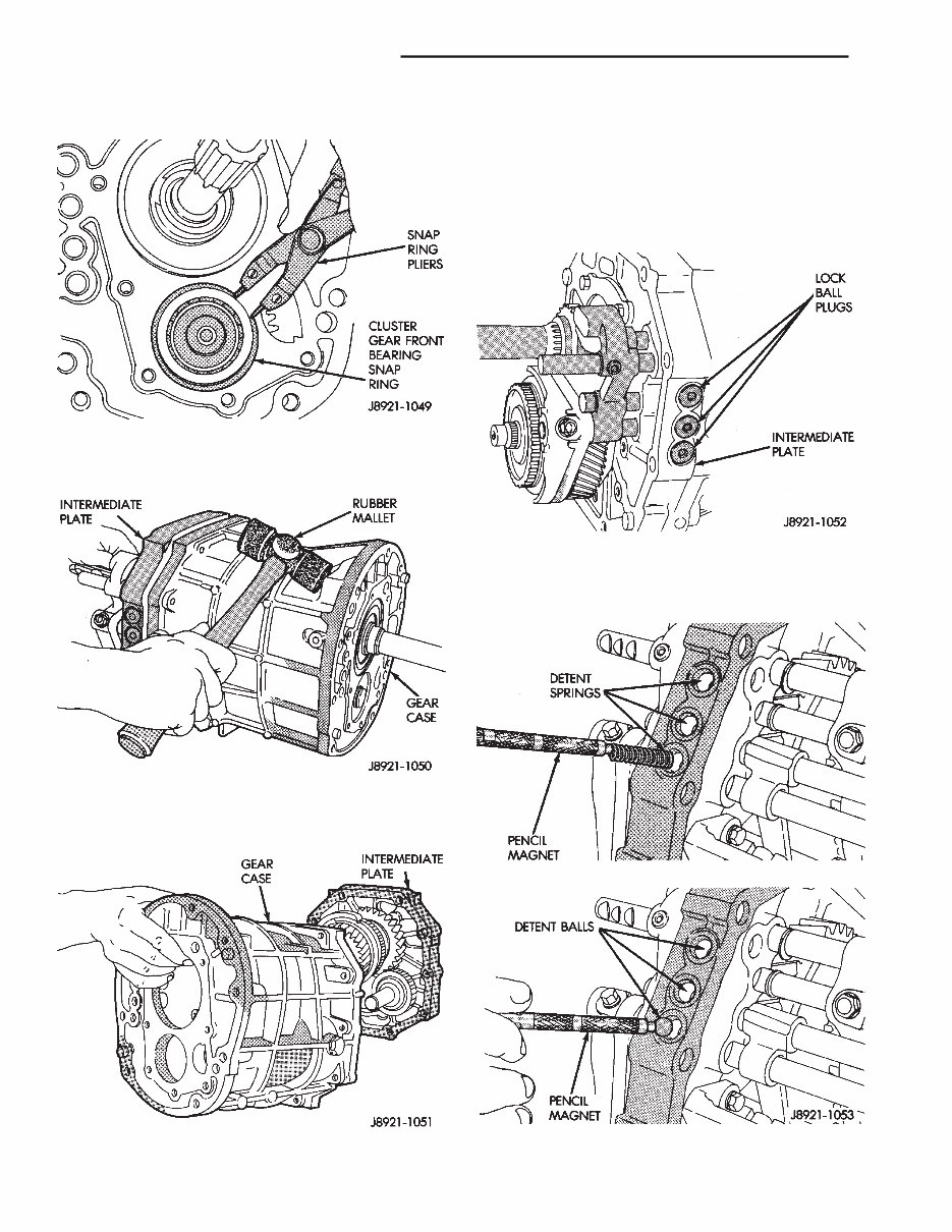
(6) Loosen and remove restrictor pins (Fig. 5). (7) Remove shift arm shaft plug (Fig. 6). (8) Remove shift arm shaft with large magnet (Fig. 7). (9) Remove shift arm (Fig. 8). (10) Remove plug for reverse shift head lock ball. Plug is at right side of adapter housing near backup light switch (Fig. 9). Fig. 5 Removing/Installing Restrictor Pins Fig. 6 Removing/Installing Shift Lever Shaft Plug Fig. 7 Removing/Installing Shift Lever Shaft Fig. 8 Shift Arm Removal/Installation Fig. 9 Removing/Installing Lock Ball Plug J AX 15 MANUAL TRANSMISSION 21 - 37
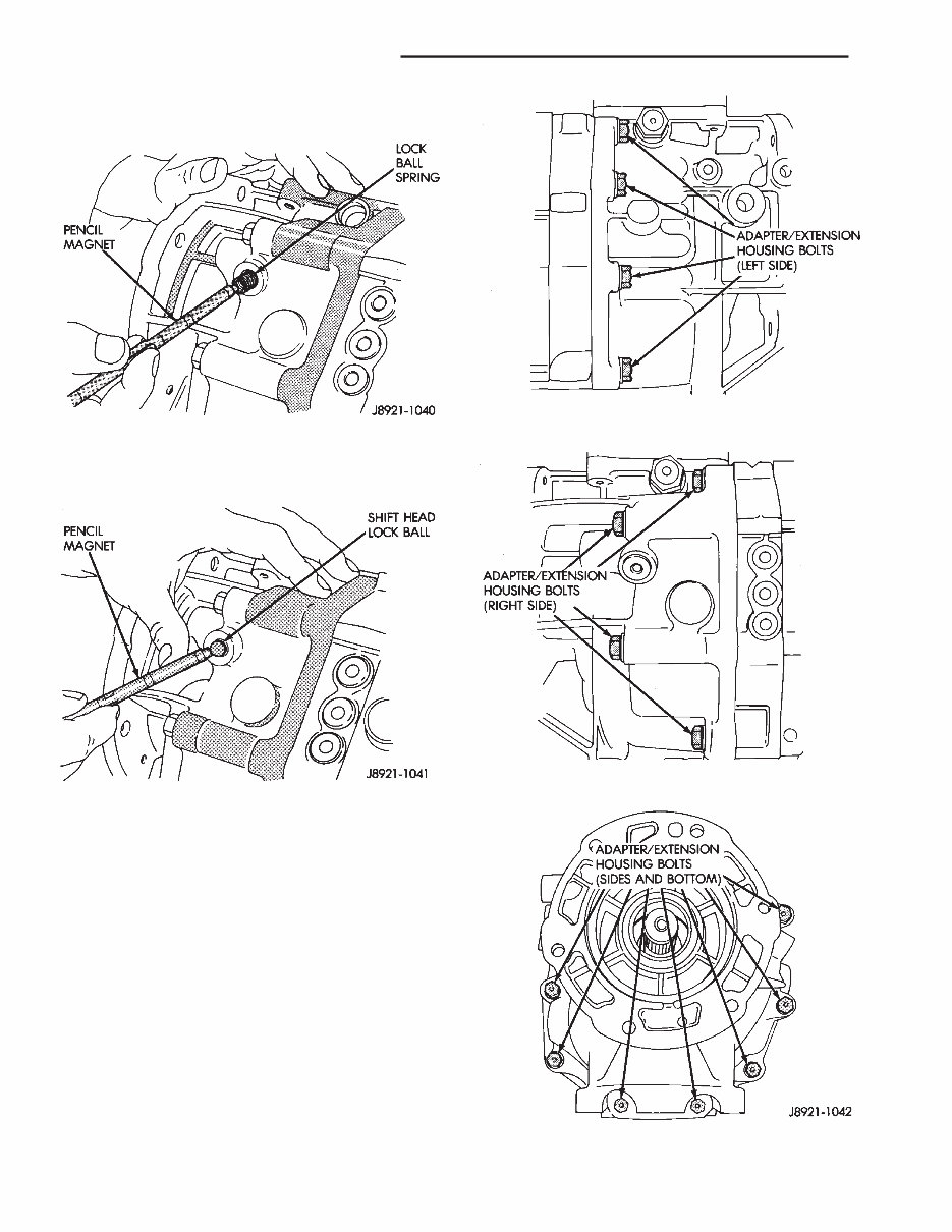
(11) Remove lock ball spring with pencil magnet (Fig. 10). (12) Remove shift head lock ball with pencil mag- net (Fig. 11). (13) Remove backup light switch from adapter/ex- tension housing. (14) On 2-wheel drive models, remove distance sensor, speedometer adapter and driven gear if not removed previously. (15) Remove adapter/extension housing bolts (Fig. 12). Fig. 10 Removing/Installing Lock Ball Spring Fig. 11 Removing/Installing Shift Head Lock Ball Fig. 12 Adapter Housing Bolt Locations 21 - 38 AX 15 MANUAL TRANSMISSION J
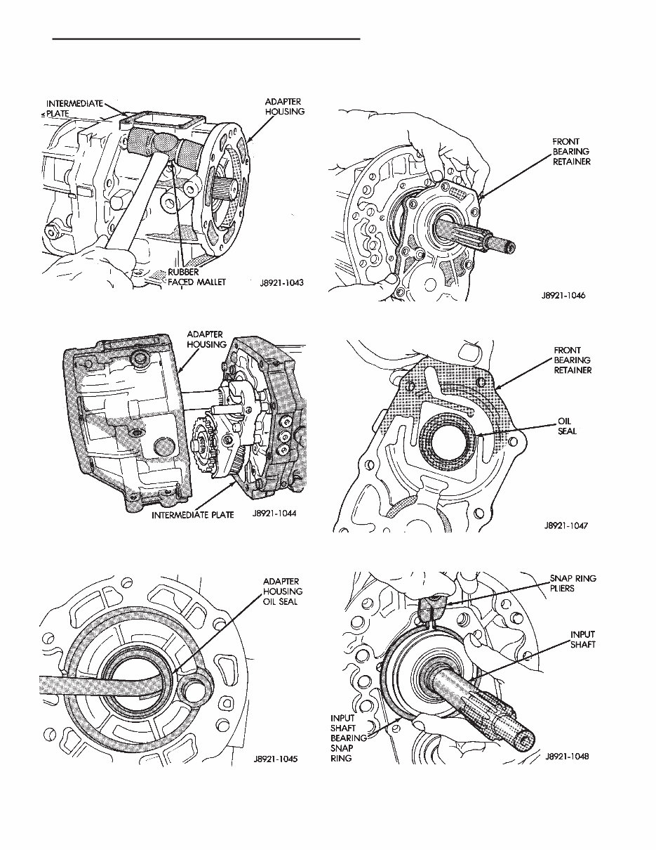
(16) Loosen adapter/extension housing with rubber mallet (Fig. 13). (17) Remove housing after loosening it (Fig. 14) (18) Remove adapter housing oil seal with pry tool (Fig. 15). GEAR CASE REMOVAL (1) Remove bearing retainer bolts and remove re- tainer (Fig. 16). (2) Remove retainer oil seal with pry tool (Fig. 17). (3) Remove input shaft bearing snap ring (Fig. 18). Fig. 13 Loosening Adapter Housing Fig. 14 Adapter Housing Removal Fig. 15 Removing Adapter Housing Seal Fig. 16 Front Bearing Retainer Removal Fig. 17 Front Bearing Retainer Seal Location Fig. 18 Removing Input Shaft Bearing Snap Ring J AX 15 MANUAL TRANSMISSION 21 - 39
(4) Remove cluster gear front bearing snap ring (Fig. 19). (5) Loosen gear case by tapping it away from inter- mediate plate with rubber mallet (Fig. 20). (6) Remove gear case from geartrain and interme- diate plate (Fig. 21). (7) On 2-wheel drive models, remove speedometer gear snap ring and remove speedometer gear and spacer from output shaft. FIFTH GEAR AND SYNCHRO ASSEMBLY REMOVAL (1) Remove three lock ball plugs from intermediate plate (Fig. 22). (2) Remove three lock ball springs and lock balls from intermediate plate with pencil magnet (Fig. 23). Fig. 19 Removing Cluster Gear Front Bearing Snap Ring Fig. 20 Loosening Gear Case Fig. 21 Gear Case Removal Fig. 22 Lock Ball Plug Locations Fig. 23 Removing/Installing Lock Ball And Spring 21 - 40 AX 15 MANUAL TRANSMISSION J
(3) Mount intermediate plate and geartrain assem- bly in vise as follows: (a) Insert two spare bolts in one bottom bolt hole in intermediate plate. Insert bolts from opposite sides of plates (Fig. 24). (b) Install enough flat washers under each bolt head to prevent bolts from touching (Fig. 24). (c) Tape bolts and washers in place and mount intermediate plate in vise (Fig. 24). (d) Clamp vise jaws securely against bolt heads (Fig. 24). Do not clamp vise jaws on intermedi- ate plate. Clamp only on bolt heads. (4) Remove fifth gear snap ring (Fig. 25). Retain snap ring for assembly reference. It is a select fit component. (5) Remove E-ring that secures reverse shift arm to fork (Fig. 26). Fig. 24 Mounting Intermediate Plate And Geartrain In Vise Fig. 25 Fifth Gear Snap Ring Removal Fig. 26 Removing Reverse Shift Arm E-Ring J AX 15 MANUAL TRANSMISSION 21 - 41
Get your hands on the comprehensive service/repair manual for the Jeep AX 15 Transmission. This manual is a valuable resource for both professional mechanics and DIY enthusiasts, providing detailed instructions and step-by-step diagrams for all workshop procedures.
By utilizing the Jeep AX 15 Transmission Service & Workshop Manual, you can effectively perform car repairs at home. This manual covers a range of models, including the Jeep AX 15 Transmission.
The manual includes in-depth coverage of the AX 15, a 5-speed, synchromesh, manual transmission. It features an overdrive range with a ratio of 0.79:1 in fifth gear. The integral shift mechanism is mounted in the shift tower portion of the adapter housing, which is used to attach the transmission to the transfer case on 4-wheel drive models. Additionally, it provides information on the use of the AX 15 in XJ and YJ models with a 4.0L engine, designed for both two-wheel drive and four-wheel drive applications.
File Format: PDF
Compatibility: All Versions of Windows & Mac
Language: English
Requirements: Adobe Reader
Ready to take on some DIY car maintenance? This manual is your go-to resource for servicing and repairing your vehicle, offering the opportunity to save money and gain valuable hands-on experience. It's time to roll up your sleeves and get started!
Recently Viewed
5,521,897Happy Clients
2,594,462eManuals
1,120,453Trusted Sellers
15Years in Business
Price:
Actual Price:
Jeep AX 15 Transmission Service & workshop Repair Manual