ENGINE TABLE OF CONTENTS page page 2.5L ENGINE .............................. 1 4.0L ENGINE ............................. 61 2.5L ENGINE TABLE OF CONTENTS page page DESCRIPTION AND OPERATION ENGINE ................................. 2 LUBRICATION SYSTEM ..................... 2 CYLINDER BLOCK......................... 5 CYLINDER HEAD.......................... 5 CRANKSHAFT ............................ 5 PISTON AND CONNECTING ROD ............. 6 CAMSHAFT .............................. 6 ROCKER ARM ............................ 6 VALVES ................................. 6 VALVE SPRING ........................... 7 CYLINDER HEAD COVER ................... 7 HYDRAULIC TAPPET ....................... 7 VALVE GUIDE ............................ 7 OIL PAN ................................. 7 VALVE STEM SEAL ........................ 8 INTAKE MANIFOLD ........................ 8 EXHAUST MANIFOLD ...................... 8 DIAGNOSIS AND TESTING ENGINE DIAGNOSIS—INTRODUCTION......... 8 SERVICE DIAGNOSIS—PERFORMANCE ....... 9 SERVICE DIAGNOSIS—MECHANICAL......... 10 INTAKE MANIFOLD LEAKAGE DIAGNOSIS ..... 13 CYLINDER COMPRESSION PRESSURE TEST . . 13 ENGINE CYLINDER HEAD GASKET FAILURE DIAGNOSIS ........................... 13 CYLINDER COMBUSTION PRESSURE LEAKAGE TEST ........................ 13 ENGINE OIL LEAK INSPECTION ............. 14 ENGINE OIL PRESSURE ................... 15 SERVICE PROCEDURES VALVE TIMING ........................... 15 VALVE, GUIDE AND SEAL .................. 15 PISTON—FITTING ........................ 17 PISTON RING—FITTING ................... 18 CONNECTING ROD BEARINGS—FITTING ..... 21 FITTING CRANKSHAFT MAIN BEARINGS ...... 23 FORM-IN-PLACE GASKETS ................. 25 ENGINE PERFORMANCE .................. 26 HONING CYLINDER BORES ................ 26 REPAIR DAMAGED OR WORN THREADS ...... 27 SERVICE ENGINE ASSEMBLY (SHORT BLOCK) .... 27 HYDROSTATIC LOCK ..................... 27 ENGINE OIL SERVICE ..................... 27 REMOVAL AND INSTALLATION ENGINE MOUNTS—FRONT ................. 29 ENGINE MOUNT—REAR ................... 30 ENGINE ................................ 31 INTAKE MANIFOLD ....................... 33 EXHAUST MANIFOLD ..................... 35 CYLINDER HEAD COVER .................. 35 ROCKER ARMS AND PUSH RODS ........... 36 VALVE SPRING AND SEAL ................. 37 CYLINDER HEAD......................... 38 CYLINDER HEAD......................... 40 HYDRAULIC TAPPETS..................... 40 VIBRATION DAMPER ...................... 41 TIMING CASE COVER OIL SEAL ............. 41 TIMING CASE COVER ..................... 42 TIMING CHAIN AND SPROCKETS ............ 43 CAMSHAFT ............................. 44 CAMSHAFT PIN REPLACEMENT ............. 45 CAMSHAFT BEARINGS .................... 47 CRANKSHAFT MAIN BEARINGS ............. 47 OIL PAN ................................ 49 OIL PUMP .............................. 50 PISTON AND CONNECTING ROD ............ 51 REAR MAIN OIL SEAL ..................... 52 DISASSEMBLY AND ASSEMBLY CYLINDER BLOCK........................ 53 CLEANING AND INSPECTION ROCKER ARMS AND PUSH RODS ........... 53 ENGINE CYLINDER HEAD .................. 54 CYLINDER BLOCK........................ 54 SPECIFICATIONS ENGINE SPECIFICATIONS.................. 55 SPECIFICATIONS—TORQUE ................ 59 SPECIAL TOOLS 2.5L ENGINE SPECIAL TOOLS .............. 60 XJ ENGINE 9-1
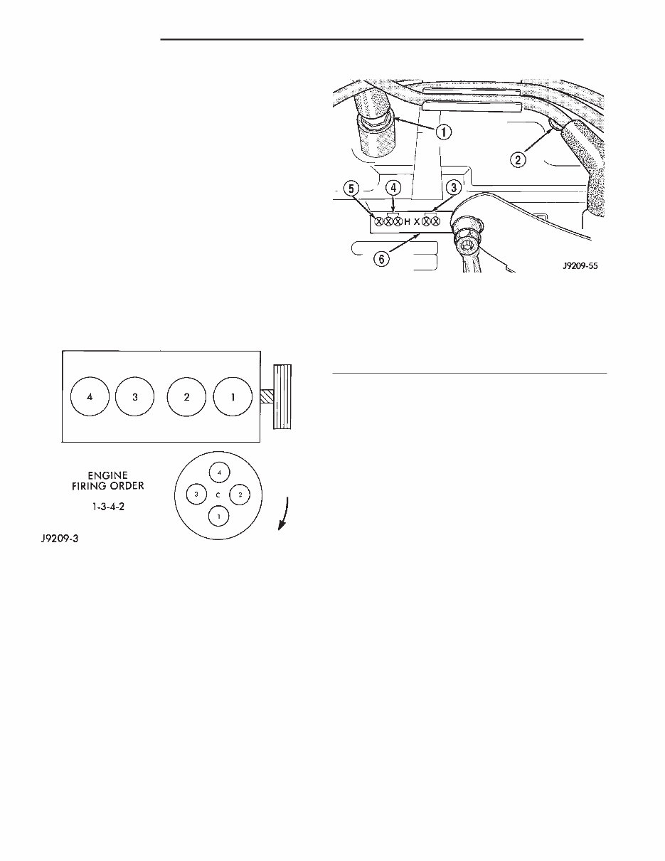
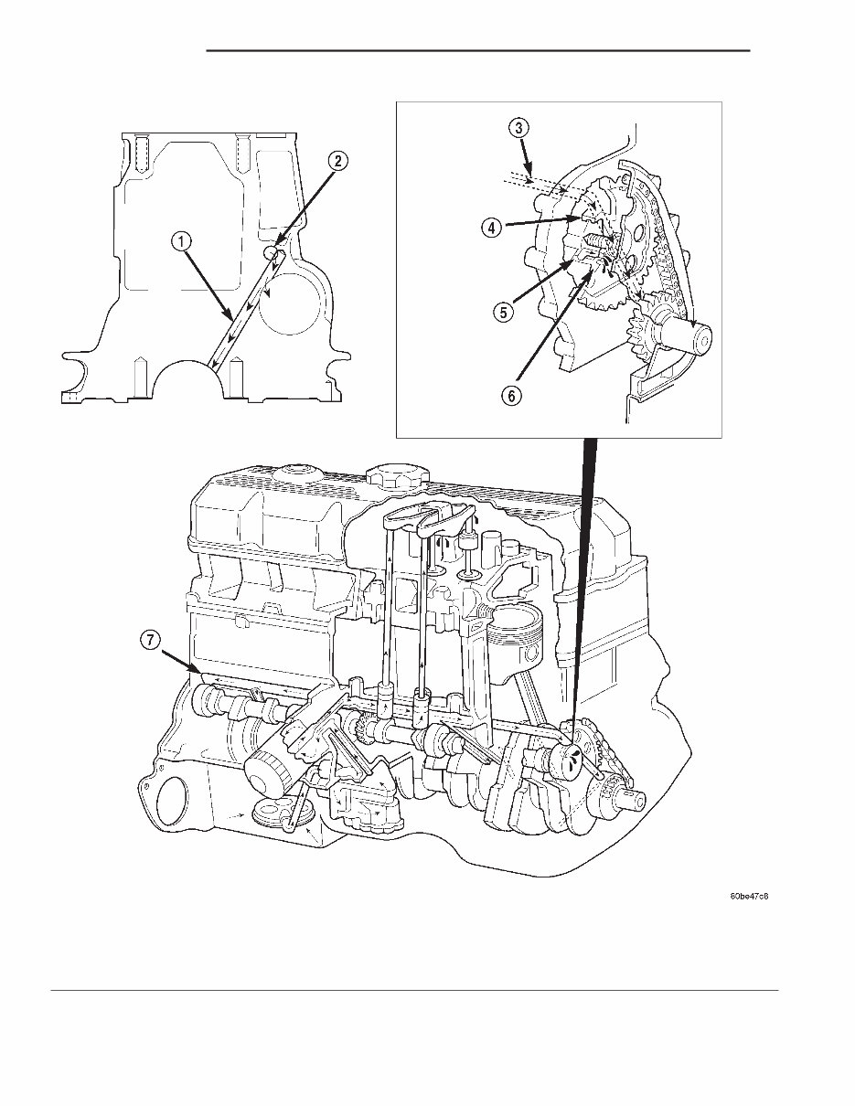
DESCRIPTION AND OPERATION ENGINE DESCRIPTION The 2.5 liter (150 CID) four-cylinder engine is an In-line, lightweight, overhead valve engine. This engine is designed for unleaded fuel. The engine cylinder head has dual quench-type combustion cham- bers that create turbulence and fast burning of the air/ fuel mixture. This results in good fuel economy. The cylinders are numbered 1 through 4 from front to rear. The firing order is 1-3-4-2 (Fig. 1). The crankshaft rotation is clockwise, when viewed from the front of the engine. The crankshaft rotates within five main bearings and the camshaft rotates within four bearings. The engine Build Date Code is located on a machined surface on the right side of the cylinder block between the No.3 and No.4 cylinders (Fig. 2). The digits of the code identify: • 1st Digit—The year (8 = 1998). • 2nd & 3rd Digits—The month (01 - 12). • 4th & 5th Digits—The engine type/fuel system/ compression ratio (HX = A 2.5 liter (150 CID) 9.1:1 compression ratio engine with a multi-point fuel injection system). • 6th & 7th Digits—The day of engine build (01 - 31). FOR EXAMPLE: Code * 801HX23 * identifies a 2.5 liter (150 CID) engine with a multi-point fuel injection system, 9.1:1 compression ratio and built on January 23, 1998. LUBRICATION SYSTEM DESCRIPTION A gear—type positive displacement pump is mounted at the underside of the block opposite the No. 4 main bearing. OPERATION The pump draws oil through the screen and inlet tube from the sump at the rear of the oil pan. The oil is driven between the drive and idler gears and pump body, then forced through the outlet to the block. An oil gallery in the block channels the oil to the inlet side of the full flow oil filter. After passing through the filter element, the oil passes from the center outlet of the filter through an oil gallery that channels the oil up to the main gallery which extends the entire length of the block. Galleries extend downward from the main oil gallery to the upper shell of each main bearing. The crankshaft is drilled internally to pass oil from the main bearing journals (except number 4 main bearing journal) to the connecting rod journals. Each connecting rod bearing cap has a small squirt hole, oil passes through the squirt hole and is thrown off as the rod rotates. This oil throwoff lubricates the camshaft lobes, distributor drive gear, cylinder walls, and piston pins. The hydraulic valve tappets receive oil directly from the main oil gallery. Oil is provided to the cam- shaft bearing through galleries. The front camshaft bearing journal passes oil through the camshaft Fig. 1 Engine Firing Order Fig. 2 Build Date Code Location 1 – NO. 4 CYLINDER 2 – NO. 3 CYLINDER 3 – DAY 4 – MONTH 5 – YEAR 6 – MACHINED SURFACE 9-2 2.5L ENGINE XJ
sprocket to the timing chain. Oil drains back to the oil pan under the number one main bearing cap. The oil supply for the rocker arms and bridged pivot assemblies is provided by the hydraulic valve tappets which pass oil through hollow push rods to a hole in the corresponding rocker arm. Oil from the rocker arm lubricates the valve train components, then passes down through the push rod guide holes in the cylinder head past the valve tappet area, and returns to the oil pan. XJ 2.5L ENGINE 9-3 DESCRIPTION AND OPERATION (Continued)
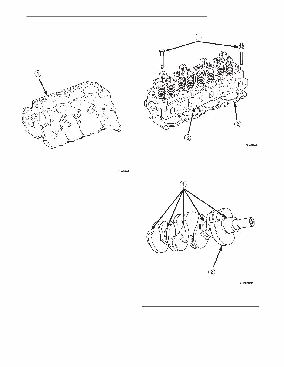
CYLINDER BLOCK DESCRIPTION The cylinder block is a cast iron inline four cylin- der design. The cylinder block is drilled forming gal- leries for both oil and coolant. CYLINDER HEAD DESCRIPTION The cylinder head is made of cast iron containing eight valves made of chrome plated heat resistant steel, valve stem seals, springs, retainers and keep- ers. The cylinder head, valve seats and guides can be resurfaced for service purposes. The cylinder head uses dual quench-type design combustion chambers which cause turbulence in the cylinders allowing faster burning of the air/fuel mix- ture, resulting in better fuel economy. The valve guides are integral to the cylinder head, They are not replaceable. However, they are service- able. CRANKSHAFT DESCRIPTION The crankshaft is constructed of nodular cast iron. Fig. 3 Cylinder Block—2.5L 1 – CYLINDER BLOCK Fig. 4 Cylinder Head 1 – CYLINDER HEAD BOLTS 2 – CYLINDER HEAD GASKET 3 – CYLINDER HEAD Fig. 5 Crankshaft—Typical 1 – MAIN BEARING JOURNALS 2 – COUNTER BALANCE WEIGHTS XJ 2.5L ENGINE 9-5 DESCRIPTION AND OPERATION (Continued)
The 2001 Jeep Cherokee (XJ) Workshop Repair Manual is a comprehensive guide tailored to assist owners and mechanics in maintaining and repairing the 2001 Jeep Cherokee (XJ) model. This manual encompasses various aspects of the vehicle, offering detailed instructions and diagrams for easy reference and understanding.
Key features of the 2001 Jeep Cherokee (XJ) Workshop Repair Manual include:
Step-by-step instructions for routine maintenance tasks such as oil changes, filter replacements, and tire rotations
Detailed explanations of various systems and components, including the engine, transmission, electrical system, and more
Troubleshooting guides to aid in diagnosing and resolving common issues
Comprehensive wiring diagrams for electrical repairs
Specifications and torque values for various parts
Whether you are a professional mechanic or a Jeep Cherokee (XJ) owner seeking to save on repair costs, the 2001 Jeep Cherokee (XJ) Workshop Repair Manual is a valuable resource that will guide you through the maintenance and repair process. With its clear instructions and detailed diagrams, this manual is an essential tool for ensuring the longevity and optimal performance of your 2001 Jeep Cherokee (XJ).

 workshop Repair Manual")