HAC-1 VENTILATION, HEATER & AIR CONDITIONER C D E F G H J K L M SECTION HAC A B HAC N O P CONTENTS HEATER & AIR CONDITIONING CONTROL SYSTEM AUTOMATIC AIR CONDITIONING BASIC INSPECTION ................................... 4 DIAGNOSIS AND REPAIR WORKFLOW ......... 4 Work Flow ................................................................ 4 INSPECTION AND ADJUSTMENT .................... 7 WITHOUT PLASMACLUSTER SYSTEM ................... 7 WITHOUT PLASMACLUSTER SYSTEM : De- scription & Inspection ............................................... 7 WITHOUT PLASMACLUSTER SYSTEM : Tem- perature Setting Trimmer ......................................... 9 WITHOUT PLASMACLUSTER SYSTEM : Foot Position Setting Trimmer ........................................ 11 WITHOUT PLASMACLUSTER SYSTEM : Inlet Port Memory Function ............................................ 12 WITH PLASMACLUSTER SYSTEM ........................ 13 WITH PLASMACLUSTER SYSTEM : Description & Inspection ........................................................... 13 WITH PLASMACLUSTER SYSTEM : Tempera- ture Setting Trimmer .............................................. 15 WITH PLASMACLUSTER SYSTEM : Foot Posi- tion Setting Trimmer ............................................... 16 WITH PLASMACLUSTER SYSTEM : Inlet Port Memory Function ................................................... 17 WITH PLASMACLUSTER SYSTEM : Exhaust Gas/Outside Odor Detecting Sensor Sensitivity Adjustment Function .............................................. 18 WITH PLASMACLUSTER SYSTEM : Auto Intake Interlocking Movement Change Function ............... 18 SYSTEM DESCRIPTION ............................ 20 COMPRESSOR CONTROL FUNCTION ...........20 Description ............................................................. 20 Fail-safe ................................................................. 20 Component Part Location ...................................... 21 Component Description .......................................... 24 AUTOMATIC AIR CONDITIONING SYSTEM ... 25 WITHOUT LEFT AND RIGHT VENTILATION TEM- PERATURE SEPARATELY CONTROL SYSTEM ....25 WITHOUT LEFT AND RIGHT VENTILATION TEMPERATURE SEPARATELY CONTROL SYSTEM : System Diagram ...................................25 WITHOUT LEFT AND RIGHT VENTILATION TEMPERATURE SEPARATELY CONTROL SYSTEM : System Description ...............................26 WITHOUT LEFT AND RIGHT VENTILATION TEMPERATURE SEPARATELY CONTROL SYSTEM : Component Part Location .....................33 WITHOUT LEFT AND RIGHT VENTILATION TEMPERATURE SEPARATELY CONTROL SYSTEM : Component Description ........................35 WITH LEFT AND RIGHT VENTILATION TEMPER- ATURE SEPARATELY CONTROL SYSTEM ..........36 WITH LEFT AND RIGHT VENTILATION TEM- PERATURE SEPARATELY CONTROL SYSTEM : System Diagram ...................................................36 WITH LEFT AND RIGHT VENTILATION TEM- PERATURE SEPARATELY CONTROL SYSTEM : System Description ...............................................38 WITH LEFT AND RIGHT VENTILATION TEM- PERATURE SEPARATELY CONTROL SYSTEM : Component Part Location .....................................50 WITH LEFT AND RIGHT VENTILATION TEM- PERATURE SEPARATELY CONTROL SYSTEM : Component Description ........................................52 ACCS (ADVANCE CLIMATE CONTROL SYSTEM) ........................................................... 54 System Diagram .....................................................54 System Description .................................................54 Component Part Location .......................................56 Component Description ..........................................57 CAN COMMUNICATION SYSTEM ................... 58 System Description .................................................58 Revision: 2013 February 2012 G Sedan
HAC-2 MODE DOOR CONTROL SYSTEM ................. 59 System Diagram .................................................... 59 System Description ................................................ 59 AIR MIX DOOR CONTROL SYSTEM .............. 61 System Diagram .................................................... 61 System Description ................................................ 61 INTAKE DOOR CONTROL SYSTEM ............... 63 System Diagram .................................................... 63 System Description ................................................ 63 BLOWER MOTOR CONTROL SYSTEM ......... 65 System Diagram .................................................... 65 System Description ................................................ 65 MAGNET CLUTCH CONTROL SYSTEM ........ 67 System Diagram .................................................... 67 System Description ................................................ 67 DIAGNOSIS SYSTEM (UNIFIED METER & A/ C AMP.) ............................................................. 69 WITHOUT PLASMACLUSTER SYSTEM ................ 69 WITHOUT PLASMACLUSTER SYSTEM : Diag- nosis Description ................................................... 69 WITH PLASMACLUSTER SYSTEM ........................ 74 WITH PLASMACLUSTER SYSTEM : Diagnosis Description ............................................................. 74 DTC/CIRCUIT DIAGNOSIS ........................ 80 POWER SUPPLY AND GROUND CIRCUIT .... 80 UNIFIED METER AND A/C AMP. ............................ 80 UNIFIED METER AND A/C AMP. : Diagnosis Pro- cedure .................................................................... 80 UNIFIED METER AND A/C AMP. .................... 81 Description ............................................................. 81 Component Function Check .................................. 81 Diagnosis Procedure ............................................. 81 MODE DOOR MOTOR ..................................... 82 Description ............................................................. 82 Component Function Check ................................ 82 Diagnosis Procedure ............................................. 82 AIR MIX DOOR MOTOR ................................... 84 WITHOUT LEFT AND RIGHT VENTILATION TEM- PERATURE SEPARATELY CONTROL SYSTEM ... 84 WITHOUT LEFT AND RIGHT VENTILATION TEMPERATURE SEPARATELY CONTROL SYSTEM : Description ........................................... 84 WITHOUT LEFT AND RIGHT VENTILATION TEMPERATURE SEPARATELY CONTROL SYSTEM : Component Function Check ............... 84 WITHOUT LEFT AND RIGHT VENTILATION TEMPERATURE SEPARATELY CONTROL SYSTEM : Diagnosis Procedure ........................... 84 WITH LEFT AND RIGHT VENTILATION TEMPER- ATURE SEPARATELY CONTROL SYSTEM .......... 85 WITH LEFT AND RIGHT VENTILATION TEM- PERATURE SEPARATELY CONTROL SYSTEM : Description ........................................................... 85 WITH LEFT AND RIGHT VENTILATION TEM- PERATURE SEPARATELY CONTROL SYSTEM : Component Function Check ............................... 86 WITH LEFT AND RIGHT VENTILATION TEM- PERATURE SEPARATELY CONTROL SYSTEM : Diagnosis Procedure ............................................ 86 INTAKE DOOR MOTOR ................................... 89 Description ............................................................. 89 Component Function Check ................................. 89 Diagnosis Procedure .............................................. 89 BLOWER MOTOR ............................................ 91 Description ............................................................. 91 Component Function Check ................................. 91 Diagnosis Procedure .............................................. 91 Component Inspection ........................................... 93 MAGNET CLUTCH ........................................... 95 Description ............................................................. 95 Component Function Check .................................. 95 Diagnosis Procedure .............................................. 95 ECV (ELECTRICAL CONTROL VALVE) ......... 97 Description ............................................................. 97 Diagnosis Procedure .............................................. 97 AMBIENT SENSOR .......................................... 99 Description ............................................................. 99 Component Function Check ................................. 99 Diagnosis Procedure .............................................. 99 Component Inspection ......................................... 100 IN-VEHICLE SENSOR ..................................... 102 Description ........................................................... 102 Component Function Check ............................... 102 Diagnosis Procedure ............................................ 102 Component Inspection ......................................... 103 SUNLOAD SENSOR ....................................... 105 Description ........................................................... 105 Component Function Check ............................... 105 Diagnosis Procedure ............................................ 105 Component Inspection ......................................... 106 INTAKE SENSOR ............................................ 108 Description ........................................................... 108 Component Function Check ............................... 108 Diagnosis Procedure ............................................ 108 Component Inspection ......................................... 109 EXHAUST GAS/OUTSIDE ODOR DETECT- ING SENSOR ................................................... 110 Description ........................................................... 110 Component Function Check ............................... 110 Diagnosis Procedure ............................................ 110 Revision: 2013 February 2012 G Sedan
HAC-3 C D E F G H J K L M A B HAC N O P IONIZER .......................................................... 113 Description ........................................................... 113 Component Function Check ................................. 113 Diagnosis Procedure ............................................ 113 ECU DIAGNOSIS INFORMATION ........... 115 UNIFIED METER AND A/C AMP. ................... 115 Reference Value .................................................. 115 Wiring Diagram - AUTOMATIC AIR CONDITION- ING SYSTEM - ..................................................... 117 Fail-safe ............................................................... 118 ECM ................................................................. 120 VQ37VHR ............................................................... 120 VQ37VHR : Reference Value ............................... 120 VQ25HR FOR USA AND CANADA ....................... 136 VQ25HR FOR USA AND CANADA : Reference Value .................................................................... 136 VQ25HR FOR MEXICO .......................................... 152 VQ25HR FOR MEXICO : Reference Value ......... 152 SYMPTOM DIAGNOSIS ........................... 169 AUTOMATIC AIR CONDITIONING SYSTEM .. 169 Diagnosis Chart By Symptom .............................. 169 INSUFFICIENT COOLING .............................. 171 Description ........................................................... 171 Inspection procedure ............................................ 171 INSUFFICIENT HEATING ............................... 173 Description ........................................................... 173 Inspection procedure ............................................ 173 NOISE .............................................................. 175 Description ........................................................... 175 Inspection procedure ............................................ 175 SELF-DIAGNOSIS CANNOT BE PER- FORMED ......................................................... 177 Description ........................................................... 177 Inspection procedure ............................................ 177 MEMORY FUNCTION DOES NOT OPERATE .. 178 Description ........................................................... 178 Inspection procedure ............................................ 178 PRECAUTION ........................................... 179 PRECAUTIONS ............................................... 179 Precaution for Supplemental Restraint System (SRS) "AIR BAG" and "SEAT BELT PRE-TEN- SIONER" .............................................................. 179 REMOVAL AND INSTALLATION ............ 180 PRESET SWITCH ........................................... 180 Exploded View ...................................................... 180 Removal and Installation ...................................... 180 UNIFIED METER AND A/C AMP. ................... 181 Exploded View ...................................................... 181 Removal and Installation ...................................... 181 AMBIENT SENSOR ........................................ 182 Exploded View ...................................................... 182 Removal and Installation ...................................... 182 IN-VEHICLE SENSOR .................................... 183 Exploded View ...................................................... 183 Removal and Installation ...................................... 183 SUNLOAD SENSOR ....................................... 184 Exploded View ...................................................... 184 Removal and Installation ...................................... 184 INTAKE SENSOR ........................................... 185 Exploded View ...................................................... 185 Removal and Installation ...................................... 185 REFRIGERANT PRESSURE SENSOR .......... 186 Exploded View ...................................................... 186 Removal and Installation ...................................... 186 DOOR MOTOR ................................................ 187 Exploded View ...................................................... 187 MODE DOOR MOTOR ............................................ 187 MODE DOOR MOTOR : Removal and Installation .. 187 AIR MIX DOOR MOTOR ......................................... 187 AIR MIX DOOR MOTOR : Removal and Installa- tion ........................................................................ 188 INTAKE DOOR MOTOR ......................................... 188 INTAKE DOOR MOTOR : Removal and Installa- tion ........................................................................ 188 EXHAUST GAS/OUTSIDE ODOR DETECT- ING SENSOR .................................................. 189 Exploded View ...................................................... 189 Removal and Installation ...................................... 189 IONIZER .......................................................... 190 Exploded View ...................................................... 190 Removal and Installation ...................................... 190 Revision: 2013 February 2012 G Sedan
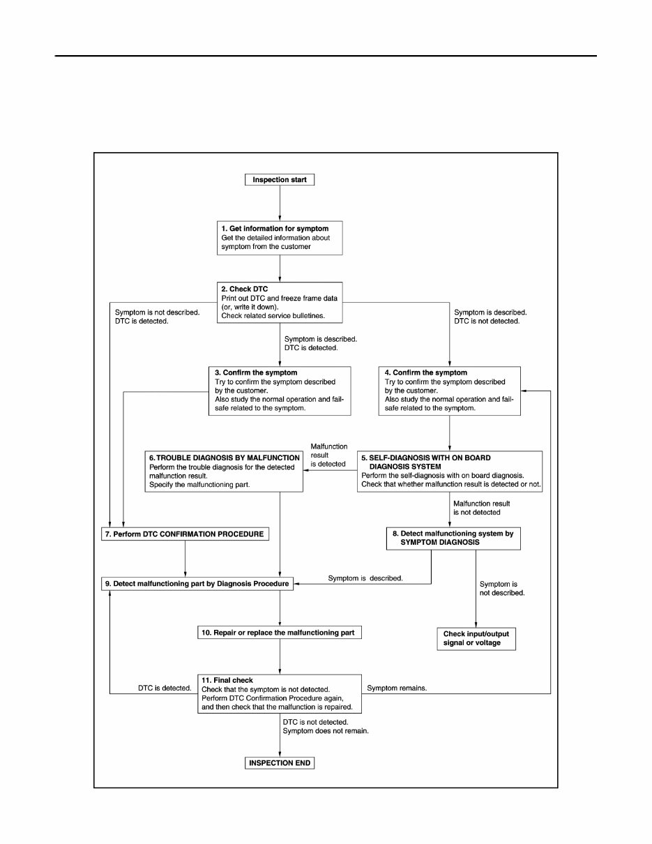
HAC-4 < BASIC INSPECTION > [AUTOMATIC AIR CONDITIONING] DIAGNOSIS AND REPAIR WORKFLOW BASIC INSPECTION DIAGNOSIS AND REPAIR WORKFLOW Work Flow INFOID:0000000007776207 OVERALL SEQUENCE DETAILED FLOW JMIIA2097GB Revision: 2013 February 2012 G Sedan
DIAGNOSIS AND REPAIR WORKFLOW HAC-5 < BASIC INSPECTION > [AUTOMATIC AIR CONDITIONING] C D E F G H J K L M A B HAC N O P 1.GET INFORMATION FOR SYMPTOM 1. Get detailed information from the customer about the symptom (the condition and the environment when the incident/malfunction occurs). 2. Check operation condition of the function that is malfunctioning. >> GO TO 2. 2.CHECK DTC 1. Check DTC. 2. Perform the following procedure if DTC is detected. - Record DTC and freeze frame data (Print them out using CONSULT.) - Erase DTC. - Study the relationship between the cause detected by DTC and the symptom described by the customer. 3. Check related service bulletins for information. Are any symptoms described and any DTC detected? Symptom is described, DTC is detected>>GO TO 3. Symptom is described, DTC is not detected>>GO TO 4. Symptom is not described, DTC is detected>>GO TO 7. 3.CONFIRM THE SYMPTOM Try to confirm the symptom described by the customer. Also study the normal operation and fail-safe related to the symptom. Verify relation between the symptom and the condition when the symptom is detected. >> GO TO 7. 4.CONFIRM THE SYMPTOM Try to confirm the symptom described by the customer. Also study the normal operation and fail-safe related to the symptom. Verify relation between the symptom and the condition when the symptom is detected. >> GO TO 5. 5.SELF-DIAGNOSIS WITH ON BOARD DIAGNOSIS SYSTEM Perform the self-diagnosis with on board diagnosis. Check that whether malfunction result is detected or not. Is malfunction result detected? YES >> GO TO 6. NO >> GO TO 8. 6.TROUBLE DIAGNOSIS BY MALFUNCTION Perform the trouble diagnosis for the detected malfunction result. Specify the malfunctioning part. >> GO TO 9. 7.PERFORM DTC CONFIRMATION PROCEDURE Perform DTC CONFIRMATION PROCEDURE for the detected DTC, and then check that DTC is detected again. At this time, always connect CONSULT to the vehicle, and check self diagnostic results in real time. If two or more DTCs are detected, refer to DTC INSPECTION PRIORITY CHART, and determine trouble diag- nosis order. NOTE: • Freeze frame data is useful if the DTC is not detected. • Perform Component Function Check if DTC CONFIRMATION PROCEDURE is not included on Service Manual. This simplified check procedure is an effective alternative though DTC cannot be detected during this check. If the result of Component Function Check is NG, it is the same as the detection of DTC by DTC CONFIR- MATION PROCEDURE. Is DTC detected? Revision: 2013 February 2012 G Sedan
The 2012 Infiniti G37 Service & Repair Manual is a comprehensive guide suitable for both professional mechanics and DIY enthusiasts. It is designed to assist in maintaining and repairing Infiniti G37 vehicles, covering a range of models such as the Base Sedan, Journey Sedan, Sport Appearance Edition Sedan, G37x Sedan, Base Coupe, Journey Coupe, Sport 6MT Coupe, G37x Coupe, and IPL Coupe.
This manual provides detailed instructions and diagrams, offering step-by-step procedures for routine maintenance, troubleshooting, and repairs on various components of the Infiniti G37. Whether it's changing the oil, replacing brake pads, or diagnosing electrical issues, this manual serves as a valuable resource for anyone working on their G37.
By following the instructions outlined in this manual, owners and mechanics can ensure the longevity and reliability of their 2012 Infiniti G37 vehicles.