

2017 Honda Ridgeline Repair Manual
What's Included?
Fast Download Speeds
Online & Offline Access
Access PDF Contents & Bookmarks
Full Search Facility
Print one or all pages of your manual

12 Volt Battery Management System Component Location Index
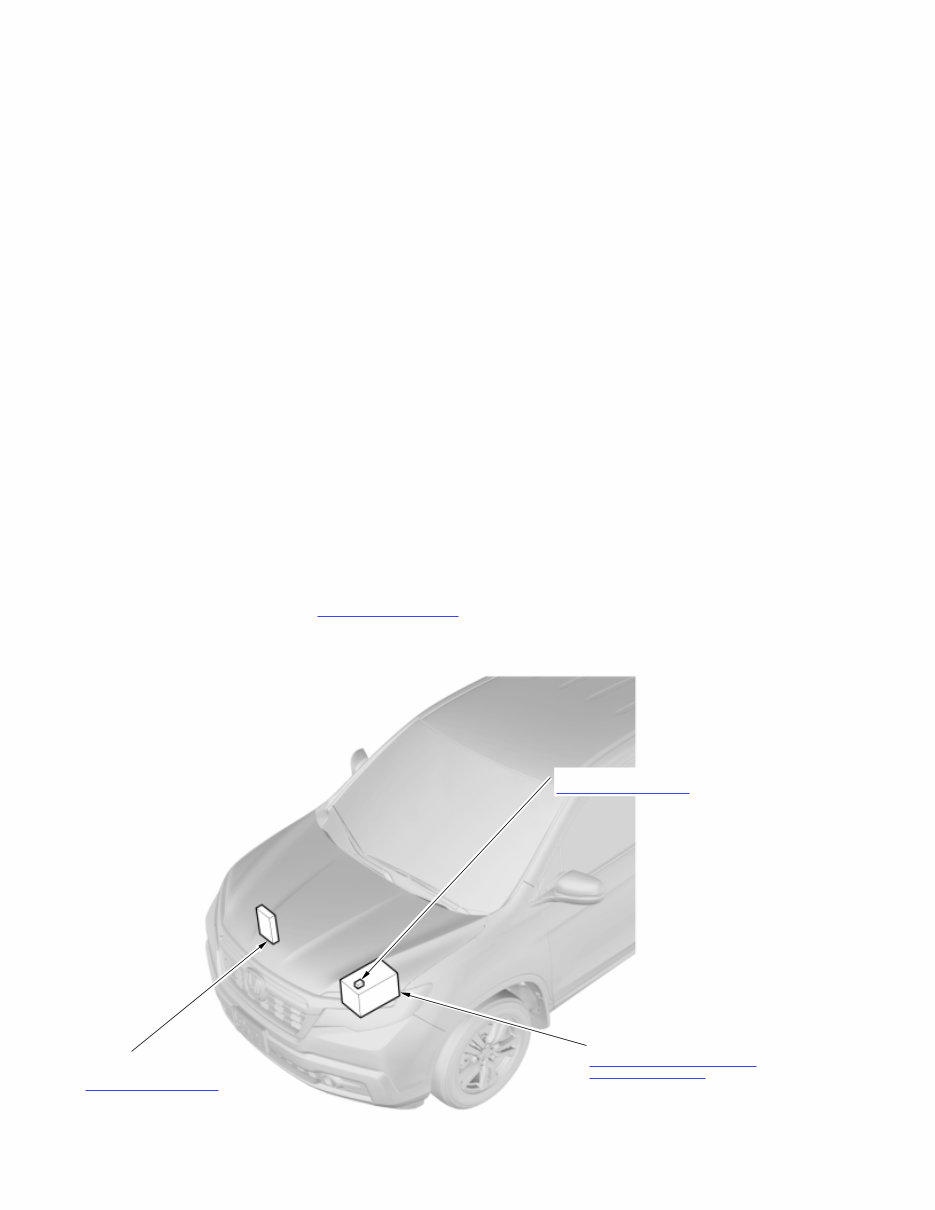
POWERTRAIN CONTROL
MODULE (PCM)
Removal and Installation
12 VOLT BATTERY SENSOR
Removal and Installation
12 VOLT BATTERY
Removal, Installation, and Test
Parasitic Draw Check
For relationships between signals in a system, refer to System Diagram.


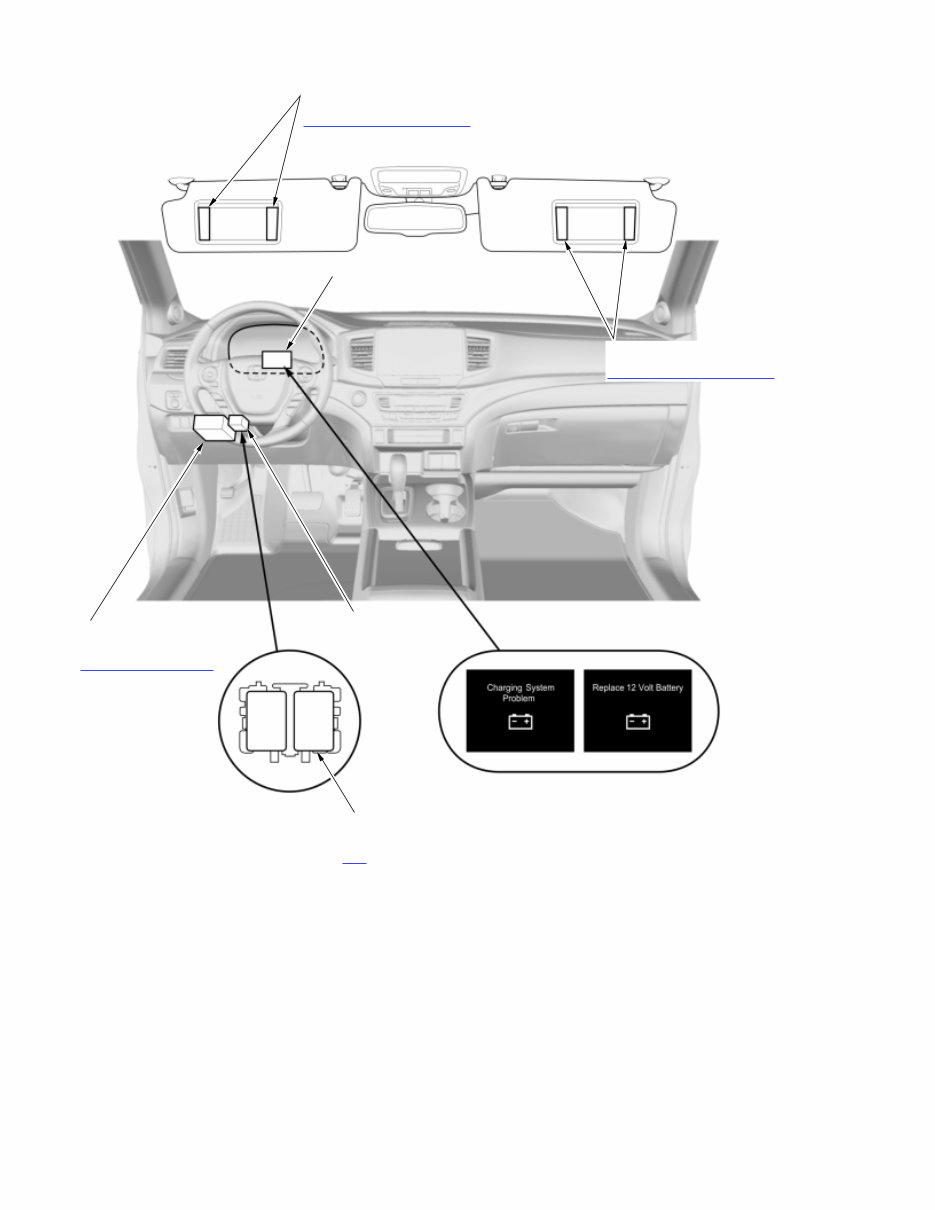
DRIVER'S VANITY DRIVER'S VANITY
MIRROR LIGHTS MIRROR LIGHTS
Removal, Installation, and Test Removal, Installation, and Test
PASSENGER'S VANITY PASSENGER'S VANITY
MIRROR LIGHTS MIRROR LIGHTS
Removal, Installation, and Test Removal, Installation, and Test
MICU
(Built into the under-dash
fuse/relay box)
Removal and Installation
MULTI-INFORMATION DISPLAY (MID)
(Built into gauge control module)
DRIVER'S VANITY
MIRROR LIGHTS
Removal, Installation, and Test
PASSENGER'S VANITY
MIRROR LIGHTS
Removal, Installation, and Test
Multi-Information Display (MID)
INTERIOR LIGHTS
CUT RELAY
(4P)
Test
RELAY HOLDER J

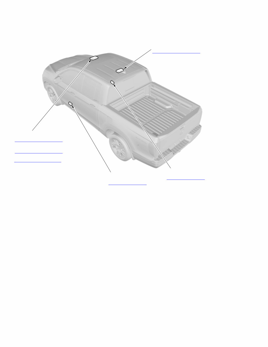
REAR INDIVIDUAL MAP LIGHT
Removal, Installation, and Test
FRONT INDIVIDUAL MAP LIGHT*
2
Remove, Installation, and Test
FRONT INDIVIDUAL MAP LIGHT
(Built into the roof console module)*
1
Removal, Installation, and Test
*1: With moonroof
*2: Without moonroof
INTERIOR LIGHT
(Built into the roof console module)*
1
Removal, Installation, and Test
DRIVER'S DOOR
COURTESY LIGHT
Removal and Installation
FRONT PASSENGER'S DOOR
COURTESY LIGHT
Removal and Installation

12 Volt Battery Management System Description
Basic Control/Function
The 12 volt battery sensor measures 12 volt battery voltage, sensor temperature, and charge/discharge currents. According to these
readings, 12 volt battery fluid temperature, internal resistance, and state of charge are sent as signals from the 12 volt battery sensor
to the gauge control module.
After the vehicle is turned to the OFF (LOCK) mode, the 12 volt battery sensor observes the charge state of the 12 volt battery. When
a designated threshold is reached, a signal is sent through the LIN circuit interface and a message is displayed on the gauge control
module. As a result, the 12 volt battery sensor can alert the driver of an over a discharge in the ACCESSORY mode or automatically
turn off interior lights through the MICU.
12 Volt Battery Management System Description - Components
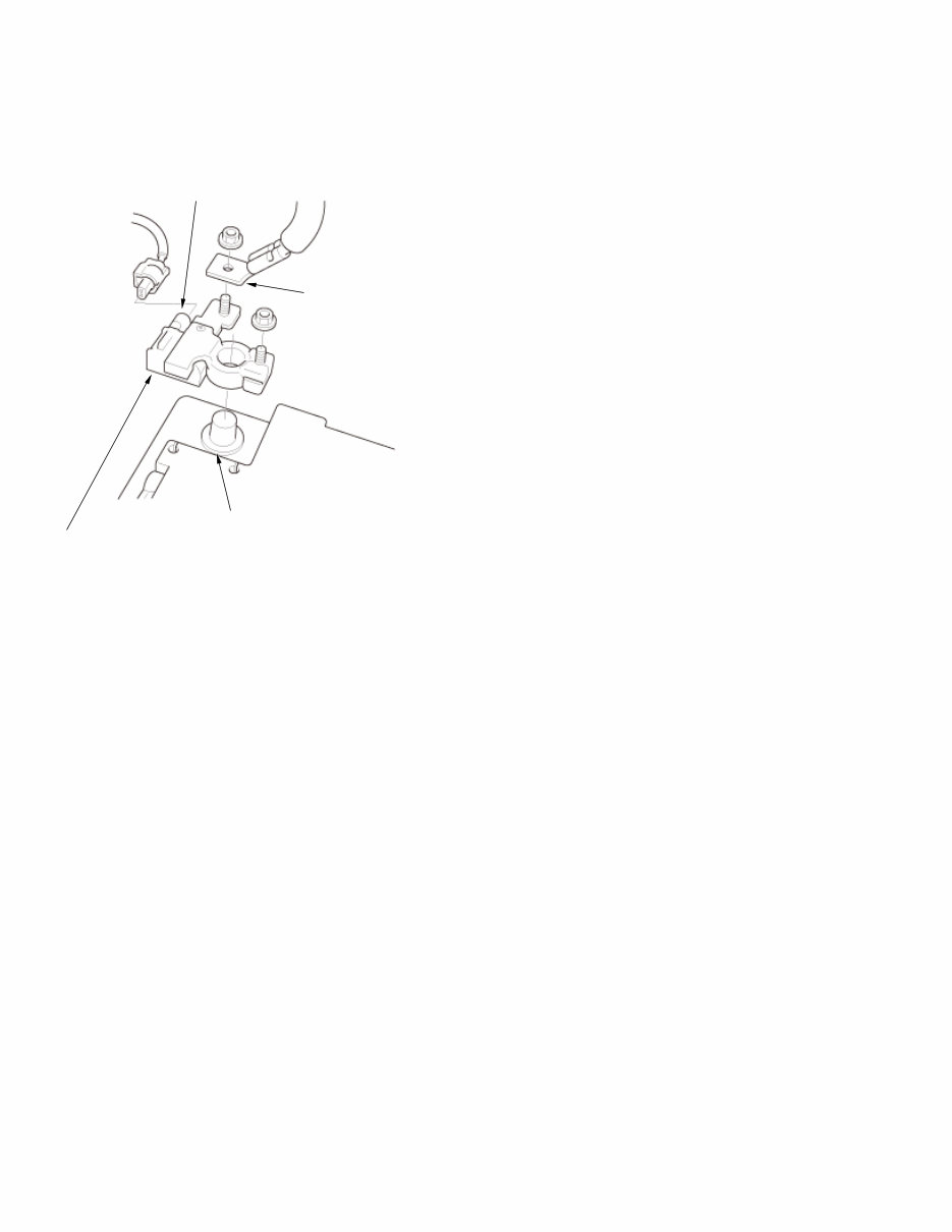
12 Volt Battery Sensor
The 12 volt battery sensor is located between the 12 volt battery negative terminal and the ground cable.
12 Volt Battery Sensor
Ground Cable
Connector
12 Volt Battery
Negative Terminal
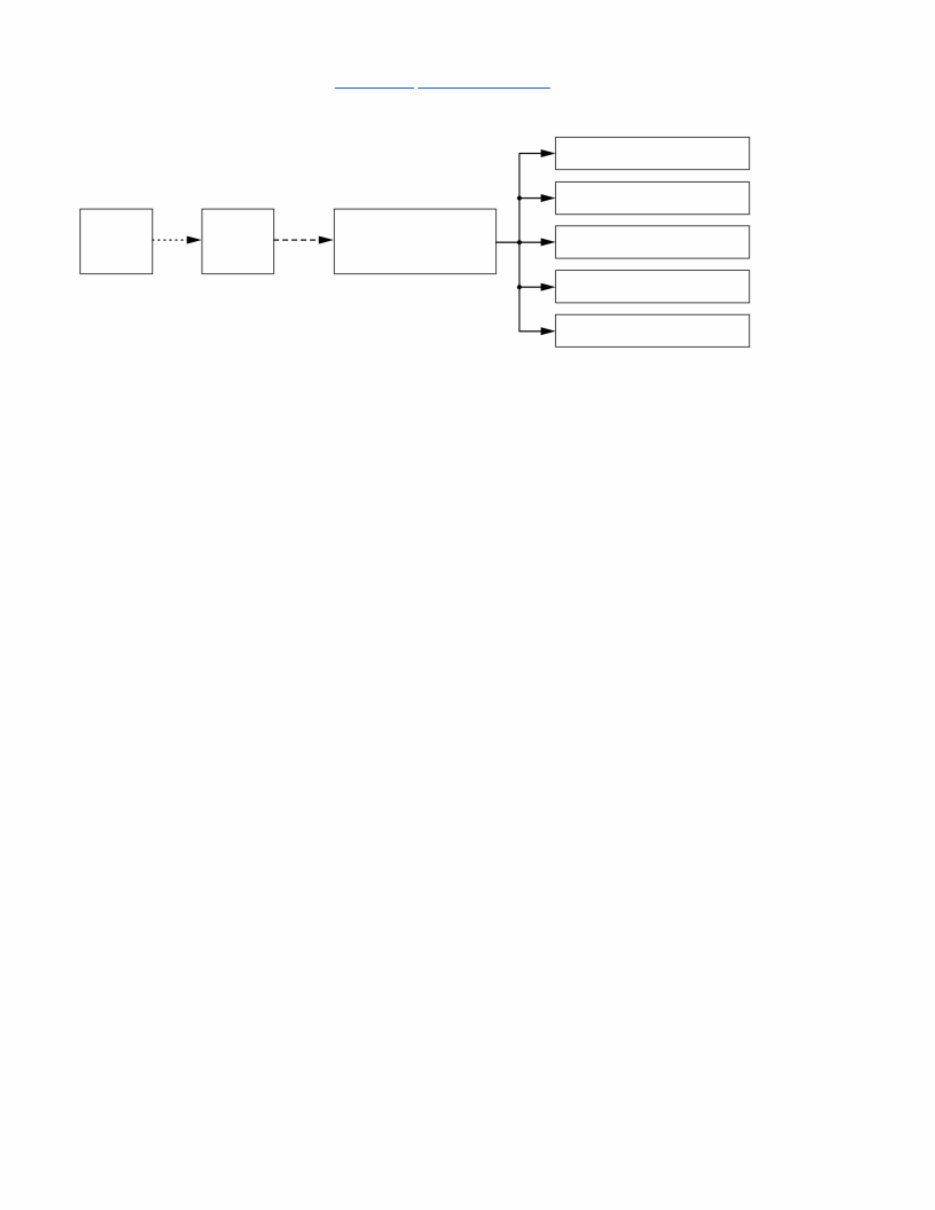
12 Volt Battery Management System Description - System Diagram
For locations of each component on the vehicle, refer to Component Location Index.
MICU 12 Volt
Battery
Sensor
Gauge
Control
Module
LIN B-CAN
∙ 12 Volt Battery
Condition Signal
Front Map Lights
Rear Map Lights
Vanity Mirror Lights
Interior Lights
Door Courtesy Lights
You're Reading a Preview
What's Included?
Fast Download Speeds
Online & Offline Access
Access PDF Contents & Bookmarks
Full Search Facility
Print one or all pages of your manual
$47.99
$62.99
Viewed 16 Times Today


Secure transaction
What's Included?
Fast Download Speeds
Online & Offline Access
Access PDF Contents & Bookmarks
Full Search Facility
Print one or all pages of your manual
$47.99
$62.99
The Repair Manual for the Honda Ridgeline 2017 provides comprehensive instructions and information for performing maintenance, Repair, and repairs on the vehicle. This manual is a valuable resource for mechanics, technicians, and DIY enthusiasts who want to ensure their Ridgeline runs smoothly and efficiently.
Contents of the Repair Manual:
- General Information
- Specifications
- Maintenance Schedules
- Engine Mechanical
- Engine Electrical
- Cooling System
- Fuel and Emissions
- Transaxle
- Steering
- Suspension
- Brakes
- Body
- Heating, Ventilation, and Air Conditioning (HVAC)
- Electrical System
- Wiring Diagrams
Each section contains detailed step-by-step procedures, diagrams, and illustrations to guide you through various tasks. Whether you need to perform routine maintenance or undertake more complex repairs, this manual provides all the essential information to help you get the job done correctly.


