0-3 Gontents Introductory pages About thismanual 0-2 Introduction to the Ford Pick-ups, Expedition and Lincoln Navigator 04 Vehicle identification numbers 0-5 Buying parts 0€ Maintenance techniques, tools andworking facilities 0-6 Jacking and towing 0-'12 Booster battery fiump) starting 0-12 Automotive chemicals andlubricants 0-13 Conversion factors 0-14 Safetyfirst! 0-15 'Troubleshooting 0-16 Ghapter 1 Tune-up and routine maintenance 1-1 Ghapter 2 ParlA VO engine 2A-1 Ghapter 2 PartB V8 engines Chapter 2 PartC General engine overhaul procedures Chapter 3 Gooling, heating and air conditioning systems Chapter 4 Fuel and exhaust svstems Chapter 5 Engine electrical systems Ghapter 6 Emissions and engine control systems Chapter 7 PartA Manual transmission 7A-l Chapter 7 PartB Automatic transmission 3.1 5-l Chapter 7 PartC Transfer case 7C-',l Chapter 8 Clutch and driveline Chapter 9 Brakes 9-l Chapter 10 Suspension and steering systems 10-l Ghapter 11 Body Ghapter 12 Chassis electricalsystem 12-1 Wiringdiagrams lndex 12-17 PALMTREESALES1967 - NO RESALE
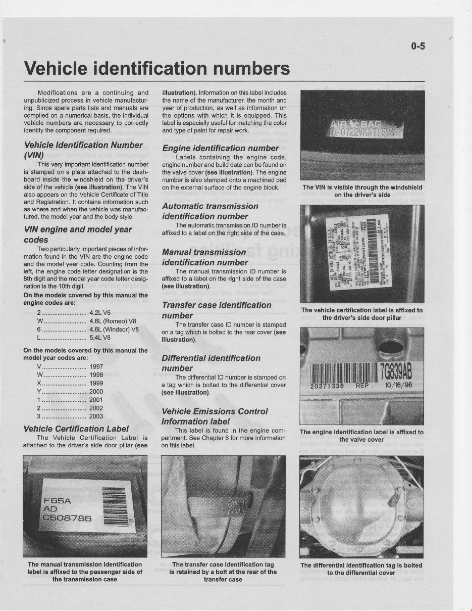
0-5 Vehicle identification numbers Modifications are a continuing and unpublicized process in vehicle manufactur- ing.Since spare parts lists and manuals are compiled on a numerical basis, the individual vehicle numbers are necessary to correctly identify thecomponent required. Veh icle I dentifi catio n N umbe r (vtN) This very importantidentification number is stamped on a plate attachedto the dash- board inside the windshield on the driver's side of the vehicle (see illustration).The VIN also appears on the Vehicle Certificate of Title and Registration. lt contains informationsuch as where and when the vehicle was manufac- tured, the model year and the body style. VIN engine and model year codes Two particularly important pieces of infor- mation found in the VINare the engine code andthe model year code. Counting fromthe left, the engine code letter designation is the 8thdigit andthe model year code letter desig- nation is the 1Oth digit. On the modelscovered by thls manual the engine codes are: 2 .......................... 4.21 V6 W ......................... 4.61 (Romeo) V8 6 ...i ...................... 4.61 (Windsor) V8 1 ........................... 5.41 V8 On the models covered by this manual the model yearcodes are: v .......................... 1997 w ......................... 1998 x.., ....................... 1999 y .......................... .2000 1 .......................... 2001 2 ..................... ..... 2002 3 .......................... 2003 Veh i cle Certifi cati on Labe I The Vehicle Certification Label is attachedto the driver's side door pillar (see The manual transmission identification label is affixed to the passenger side of the transmission case i!lustration). Information onthis label includes the name of the manufacturer, the month and year of production, as wellas information on the options with whichit is equipped. This label is especially useful for matching thecolor andtype of paint for repair work. Engine identification number Labelscontaining the enginecode, engine number and build date can befound on thevalve cover (see illustration). The engine number is also stamped onto a machined pad on theexternal surface of theengine block. Automatic trans m ission identificationnumber The automatic transmission lD number is affixed to a label on the right side of the case. Manualtransmission identificationnumber Themanual transmission lD number is affixed to a label on the right sideof the case (see illustratlon). Transfer c ase ide ntific atio n number The transfer case lD number is stamoed on a tagwhich is bolted to the rear cover (see illustration). D ifferenti al i dentifi cati on number The differential lD number is stamped on a tag which is bolted to the differential cover (see illustration). Ve hi cle Emrbsions Co ntro I lnformation label Thislabel is'found in the engine com- partment. SeeChapter 6 for more information onthislabel. The transfer case identification tag is retained by a bolt at the rear of the transfer case The VIN is visible through the windshield on the driver's side Thevehiclecertification label is affixedto the driver'g sidedoor pillar The differential identification tag is bolted to the differential cover The engine identification label ls affixed to the valve cover PALMTREESALES1967 - NO RESALE
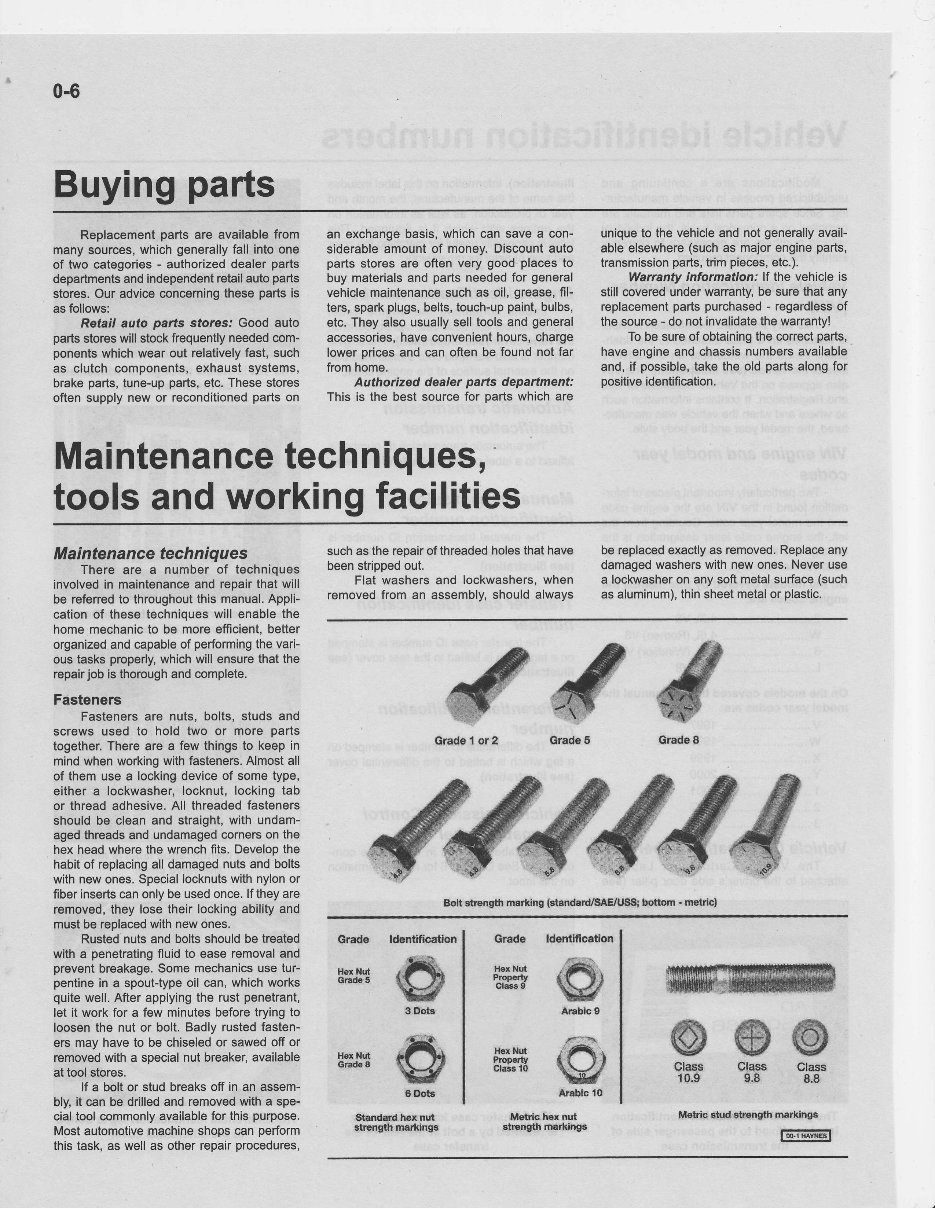
0-6 Buying parts Replacement partsare available from many sources, which generally fall intoone of two calegories - authorized dealer parts departments andindependent retail auto parts stores. Our advice conceming thesepartsis as follows: Retail auto parts sto/es.' Good auto parts stores willstock frequently needed com- ponents which wearout relatively fast,such as clutchcomponents, exhaust systems, brake parts, tune-up parts, etc.These stores oftensupply new or reconditioned partson an exchange basis, whichcan savea con- siderable amount of money. Discount auto parts stores are often very good- placesto buy materials and parts needed for general vehicle maintenance suchas oil, grease, fil- ters, spark plugs, belts, touch-up paint, bulbs, etc.They alsousually selltools andgeneral accessories, haveconvenient hours, charge lower prices and can oftenbe found not far fromhome. Authorized dealer parts department: This is the bestsource for parts whichare unique to the vehicle andnotgenerally avail- ableelsewhere (such as major engine parts, transmission parts, trim pieces, etc.). Warranty informatlon: lf the vehicle is stillcovered under wananty, be surethatany replacement partspurchased - regardless of the source - do not invalidate thewananty! Tobe sure of obtaining the correct parts, have engine and chassis numbers available and,if possible, takethe old parts along for positive identification. Maintenance techniques, tools andworking facilities Maintenancetech niques Thare are a numberof techniques involved in maintenance and repair thatwill be referred to throughout this manual, Appli- cation of these techniques will enable the home mechanic to be moreefficient, better organized andcapable of performing the vari- ous tasksproperly, which will ensure thatthe repair job is thorough andcomplete. Fasteners Fasteners are nuts,bolts, studsand screws used to hold two or more parts together. There are a few things to keepin mind when working withfasteners. Almost all of themuse a locking device of some type, eithera lockwasher, locknut, locking tab or thread adhesive. All threaded fasteners should be cleanand straight, with undam- aged threads and undamaged corners on the hex head where the wrench fits. Develop the habit of replacing all damaged nutsand bolts withnewones. Special locknuts with nylon or fiber inserts canonly be used once. lf they are removed, they losetheirlocking ability and must be replaced withnew ones. Rusted nutsand bolts should be treated with a penetrating fluid to ease removal and prevent breakage. Somemechanics usetur- pentine in a spout-type oil can, which works quite well. Afterapplying the rustpenetrant, let it work for a few minutes before tryingto loosen the nut or bolt.Badly rusted fasten- ers may haveto be chiseled or sawed off or removed witha soecial nut breaker, available at toolstores. lf a boltor stud breaks off in an assem- bly,it can be drilled and removed witha spe- cialtool commonly available for this purpose. Most automotive machine shops can perform this task,as well as otherrepair procedures, such as the repair of threaded holes that have been stripped out. Flat washers and lockwashers, when removed from an assembly,should always be replaced exactly as removed. Replace any damaged washers withnew ones. Never use a lockwasher on anysoftmetal surface (such as aluminum), thin sheet metal or plastic. Grado l!.8 lilut Cr&S H6rftA Grd6A Standard hexnul sirBngilh marldngs @@@ Class Clas 10.9 S.8 Metie €ud sq€ngth marklngs lslmffil ## d GradF I Grade 1 or 2 Grada 5 Bolt stnng0r rlar*lng (sl8ndardFAf,/Us8; bottom - moltlc) ld6ntifica$orl #$,, &ilSf Arabic 0 ,{F,. I'.I *.I i{tC,t Araua 10 iler l*rt Pmprty Clffi9 llcr lklt Pfoprrtt ClmlO ldentiflooton ^re. T3I FI w g Dole 1fi& *Flt aL.r4t E,-l' 6 Dot! Itetrio hqx nut BtrEnlth matldnge Class 8.8 PALMTREESALES1967 - NO RESALE
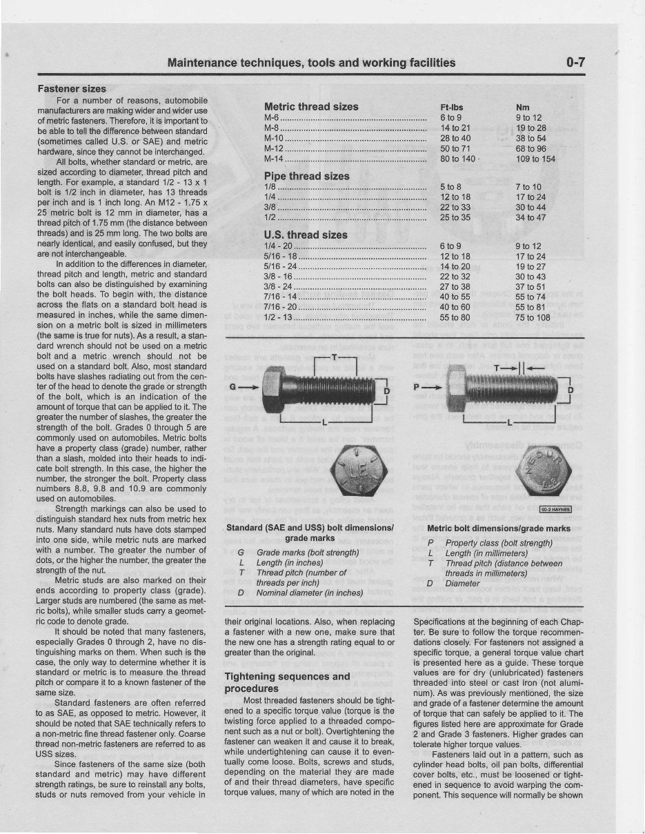
Maintenance techniques, tools and working facilities 0-7 Fastener sizes For a number of reasons, automobile manufacturers aremaking wider and wider use of metric fasteners. Therefore, it is imporiant to be able to tellthedifierence between standard (sometimes called U.S.or SAE)and metric hardware, since they cannot be interchanged. All bolts, whether standard or metric, are sized according to diameter, thread pitci and fength. Forexample, a standard 112 - 13 x 1 bolt is 1/2 inch in diametet has 13 threads per inch and is 1 inchlong. An M12 - 1.75 x 25 metric bolt is 12 mm in diameter, has a thread pitch of 1,75 mm(the distance between threads) andis 25 mmlong. Thetwo bolts are nearly identical, andeasily confused, butthey arenotinterchangeable. ln addition to the differences in diameter. thread pitchand length, metric and standard bolts canalso be distinguished by examining the bolt heads. To begin with,the distance across the flats on a standard bolt headis measured in inches, while the same dimen- sionon a metric bolt is sizedin millimeters (the same is true for nuts). As a result, a stan- dardwrench should not be usedon a metric boltand a metric wrench should not be used on a standard bolt. Also.most standard bolts have slashes radiating outfrom the cen- ter of the head to denote thegrade or strength of the bolt, which is an indication of the amount of torque thatcanbe applied to it.The greater the number of slashes, thegreater the strength of the bolt.Grades 0 through 5 are commonly usedon automobiles. Metric bolts havea property class(grade) number, rather than a slash, molded into their heads to indi- cateboltstrength. In this case, the higher the number, the stronger the bolt.Property class nuinbers 8.8, 9.8 and 10.9are commonly used on automobiles. Strength markings can alsobe used to distinguish standard hexnuts frommetric hex nuts. Many standard nutshave dotsstamped intoone side, whilemetric nutsare marked with a number. The greater the number of dots, or the higher the number, thegreater the strength of the nut. Metric studsare also marked on their ends according to property class (grade). Larger studs arenumbered (the same as met- ric bolts), while smaller studs carry a geomet- ric codg to denote grade. It should be noted that many fasteners, especially Grades 0 through 2, have no dis- tinguishing marks on them. When suchis the case, the onlyway to determine whether it is standard or metricis to measure the thread pitch or @mpare it to a known fastener of the same size. Standard fasteners are often referred to as SAE, as opposed to metric. However, it should be noted thatSAE technically refers to a non-metric finethread fastener only. Coarse thread non-metric fasteners are refened to as USS sizes. Since fasteners of the same size(both standard and metric)may have different strength ratings, be sure to reinstall anybolts, studs or nutsremoved from yourvehicle in U.S. threadsizes 1t4 - 20 FtJbs 6tog 14to21 28to 40 50 to 71 80to 140. 5to8 12to18 221o33 25 to 35 6to9 12to18 14to20 22to 32 27 to38 40 to 55 40 to 60 55 to 80 Nm 9to12 19to 28 38 to 54 68 to 96 109 to 154 7to10 '17 to24 30 to 44 34to 47 9to12 17to24 19 to 27 30 to 43 37to 51 55 to 74 55to 81 75to 108 Q-> Standard (SAE and USS) bolt dimensions/ grademarks G Grade marks(boft strength) L Length (in inches) T Thread pitch (number of threads perinch) D Nominal diameter (in inches) P..-..> fmffil Metricbolt dimensions/grade marks P Property class (bolt strength) L Lenglh (in millimeters) T Thread pitch (distance between threads in millimeters) D Diameter their original locations. Also, when replacing a fastener with a new one, makesurethat the newone hasa strength rating equal to or greater than the original. Tightening sequences and procedures Most threaded fasteners should be tight- ened to a specific torque value (torque is the twisting force applied to a threaded compo- nent such as a nut or bolt). Overtightening the fastener can weaken it and cause it to break, while undertightening can cause it to even- tually come loose. Bolts, screws and studs, dependingon the materialthey.are made of and their thread diameters,have specific torque values, many of which are noted in the Specifications at the beginning of each Chap- ter. Be sure to followthe torquerecommen- dations closely. Forfasteners not assigned a specific torque, a general torque valuechart is presented hereas a guide. These torque values are for dry (unlubricated) fasteners threaded into steelor cast iron (not alumi- num). As was previously mentioned, the size andgrade of a fastener determine the amount of torque that cansafely be applied to it. The figures listed here are approximate for Grade 2 and Grade 3 fasteners. Higher grades can tolerate higher torque values. Fasteners laid out in a pattem, suchas cylinder headbolts, oil pan bolts, difierential cover bolts, etc.,must be loosened or tight- enedin sequence to avoid warping the com- ponent. This sequence will normally beshown tL PALMTREESALES1967 - NO RESALE
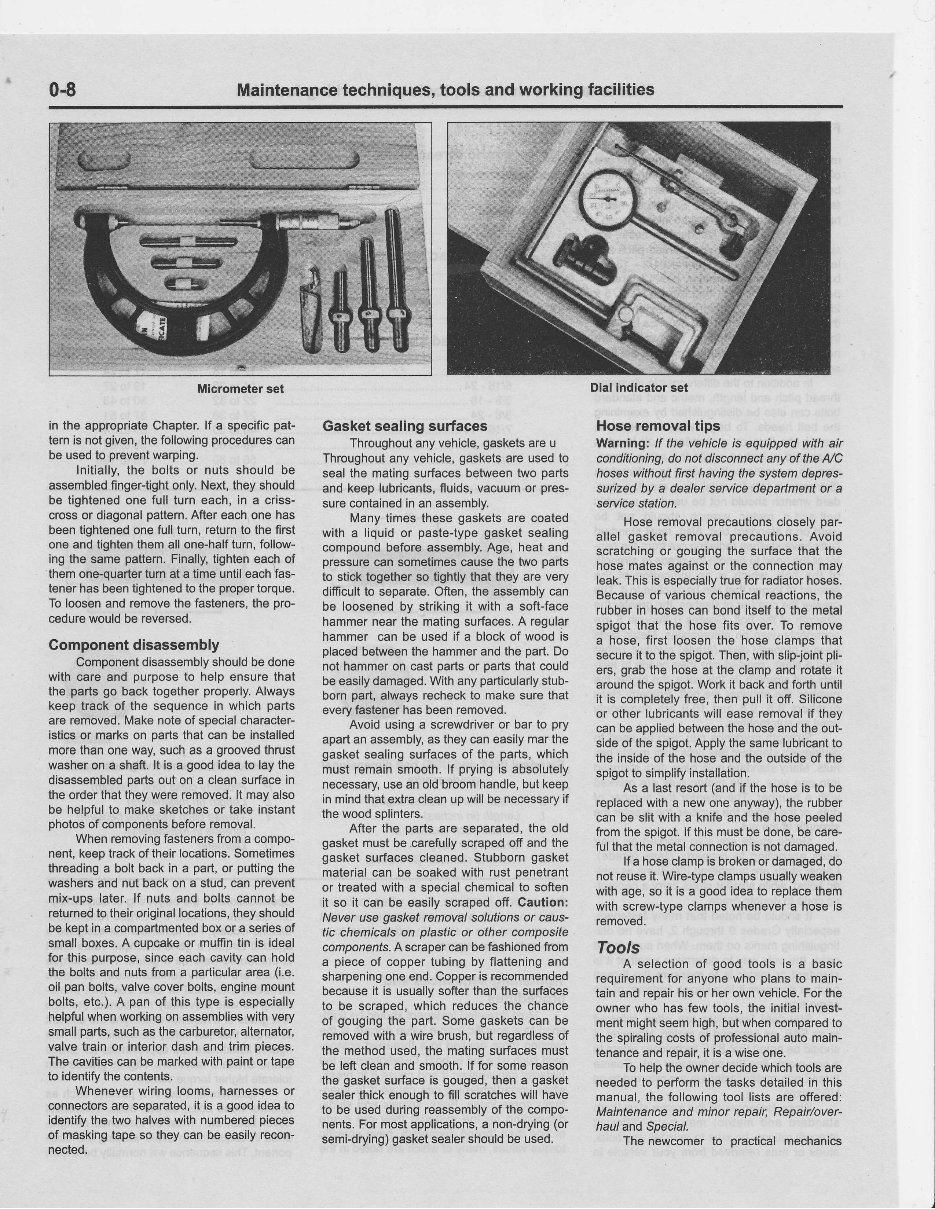
0-8 Maintenance techniques, tools and working facilities Micrometer set Dial indicator set in the appropriate Chapter.lf a specific pat- tern is not given, the following procedures can be used to prevent warping. Initially, the bolts or nuts should be assembled finger{ightonly.Next,they should be tightened one full turn each, in a criss- cross or diagonal pattern. After each one has been tightened one full turn, returnto the first one and tighten them all one-half turn, follow- ing the same pattern. Finally, tighteneach of them one-ouarter turn at a time untileach fas- tener has beentightened to the proper torque. To loosenand removethe fasteners, the pro- cedure would be reversed. Component disassembly Component disassembly should be done with care and purposeto help ensure that the parts go back together properly. Always keep track of the sequencein which parts are removed. Make note of special character- isticsor marks on parts that can be installed more than one way, such as a grooved thrust washeron a shaft. lt is a good idea to lay the disassembled parts out on a clean surfacein the orderthat they were removed. lt may also be helpful to make sketches or take instant photos of components before removal. When removing fasteners from a compo- nent,keep trackof their locations. Sometimes threading a bolt back in a part, or putting the washersand nut back on a stud, can prevent mix-uos later. lf nuts and bolts cannot be returned to theiroriginal locations, they should be kept in a compartmented box or a series of small boxes.A cupcakeor muffintin is ideal for this purpose,since each cavity can hold the bolts and nuts from a particular area (i.e. oil pan bolts,valve cover bolts,enginemount bolts,etc.).A pan of this type is especially helpful when working on assemblies with very small parts, such as the carburetor, alternator, valve train or interior dash and trim pieces. The cavities can be marked with paintor tape to identify the contents. Wheneverwiring looms, harnesses or connectors are separated, it is a good idea to identify the two halveswith numbered pieces of masking tape so they can be easily recon- nected. Gasket sealing surfaces Throughout any vehicle, gaskets are u Throughout any vehicle,gasketsare used to seal the mating surfaces betweentwo parts and keep lubricants, fluids, vacuumor pres- sure contained in an assembly. Many times these gasketsare coated with a liquid or paste-type gasket sealing compound before assembly. Age, heat and pressure can sometimes cause the two parts to stick togetherso tightlythat they are very difficult to separate. Often,the assembly can be loosened by striking it with a soft-face hammer near the mating surfaces. A regular hammer can be used if a block of wood is olacedbetween the hammerand the part. Do not hammeron cast oarts or oarts that could be easily damaged. With any particularly stub- born part, always recheckto make sure that everyfastener has been removed. Avoid using a screwdriver or bar to pry apartan assembly, as they can easilymar the gasket sealing surfaces of the parts,which must remainsmooth.lf pryingis absolutely necessary, use an old broomhandle, but keep in mindthat extracleanup will be necessary if the wood solinters. After the oarts are seoarated. the old gasket must be carefully scrapedoff and the gasket surfacescleaned.Stubborngasket material can be soaked with rust penetrant or treated with a soecial chemical to soften it so it can be easily scrapedoff. Gaution: Never use gasket removal solutionsor caus- tic chemicals on plastic or other composite components. Ascraper can be fashioned from a piece of copper tubing by flattening and sharpening one end. Copperis recommended becauseit is usually softer than the surfaces to be scraped,which reduces the chance of gougingthe part. Some gasketscan be removed with a wire brush,but regardless of the methodused, the matingsurfaces must be left clean and smooth. lf for some reason the gasket surface is gouged, then a gasket sealerthick enoughto fill scratches will have to be used during reassembly of the compo- nents.For most applications, a non-drying (or semi-drying) gasketsealer shouldbe used. Hoseremoval tips Warning: lf the vehicle is equipped with air conditioning, do not disconnectany of the NC hoses without first having lhe syslem depres- surized by a dealer service department or a service station. Hose removal precautions closelypar- allel gasket removal precautions. Avoid scratching or gougingthe surfacethat the hose mates againstor the connection may leak. This is especially true for radiator hoses. Because of variouschemical reactions, the rubber in hoses can bond itself to the metal spigot that the hose fits over. To remove a hose, first loosen the hose clamps that secureit to the spigot. Then,with slip-joint pli- ers, grab the hose at the clamp and rotate it around the spigoi.Work it back and forth until it is completely free, then pull it off. Silicone or other lubricants will ease removal if they can be applied between the hose and the out- side of the spigot. Apply the same lubricant to the insideof the hose and the outsideof the spigot to simplify installation. As a last resort(and if the hose is to be replaced with a new one anyway), the rubber can be slit with a knife and the hose peeled from the spigot.lf this must be done, be care- ful that the metalconnection is not damaged. lf a hose clamp is broken or damaged, do not reuseit. Wiretype clampsusually weaken with age, so it is a good idea to replace them with screw{ype clamps whenever a hose is removed. Iools A selection of good tools is a basic requirement for anyonewho plansto main- tain and reoairhis or her own vehicle. For the owner who has few tools,the initialinvest- ment mightseem high,but when compared to the spiraling costs of professional auto main- tenance and repair, it is a wise one. To helo the ownerdecide whichtools are needed to perform the tasks detailed in this manual, the following tool lists are offered: Maintenance and minor repair, Repair/over- haul and Special. The newcomer to practical mechanics PALMTREESALES1967 - NO RESALE
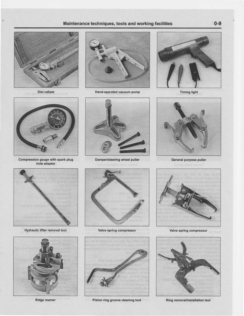
Maintenance techniques, tools and working facilities 0-9 ru Damper/steering wheel puller Timing light General purpose puller Valve springcompressor Ring removal/installation tool Compression gauge with sparkplug holeadapter Hydraulic lifter removal tool Ridge reamer Valve springcompressor Piston ring groove cleaning tool Dial caliper Hand-operated vacuum pump PALMTREESALES1967 - NO RESALE
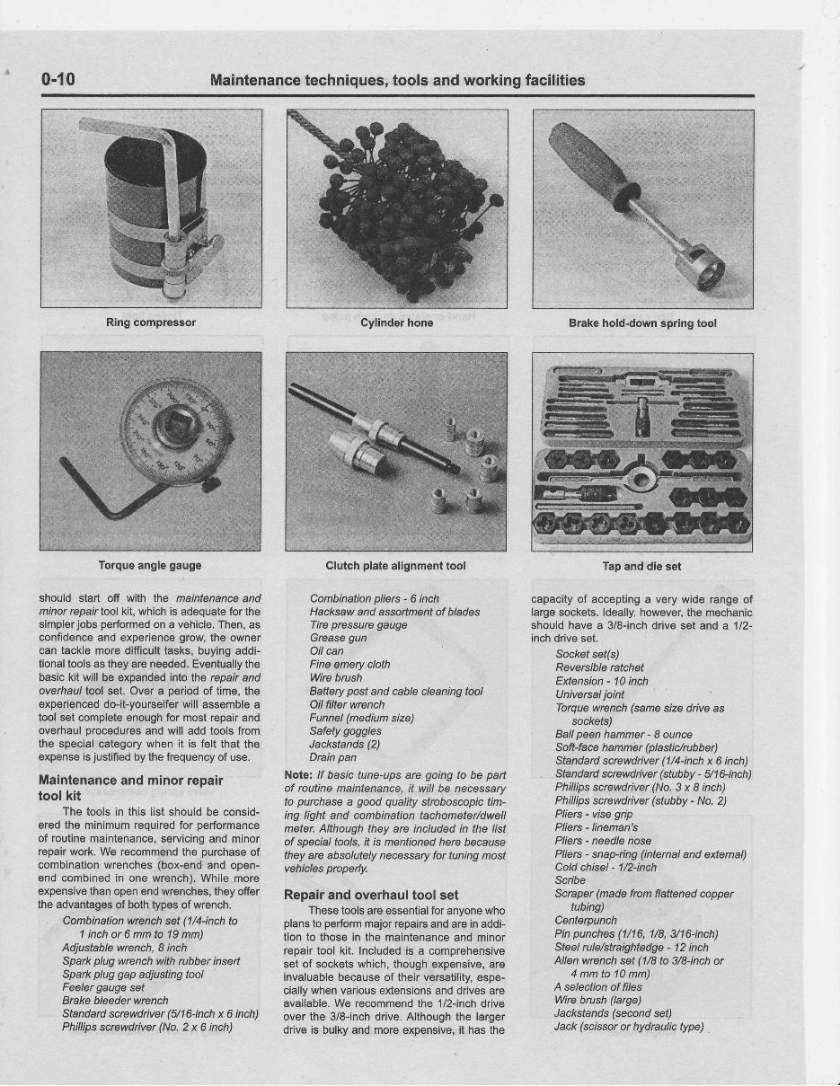
0-10 Maintenance techniques, tools and working facilities Ring compressor shoufd start off with the maintenance and minorrepairtool kit,which is adequate for the simpler jobsperformed on a vehicle, Then, as confidence and experience grow the owner can tackle more difficult tasks, buying addi- tional tools as they areneeded, Eventually the basickit will be expanded intothe repair and overhaul tool set. Overa period of time,the experienced do-it-yourselfer will assemble a tool set complete enough for mostrepair and overhaul procedures and will add toolsfrom the special category whenit is felt that the expense is justified by thefrequency of use. Maintenance and minor repair toolkit The toolsin this list should be consid- eredthe minimum required for performance of routine maintenance, servicing and minor repair work. We recommend the purchase of combination wrenches (box-end and open- end combined in one wrench). Whilemore expensive than open endwrenches, they ofier the advantages of both types of wrench. Combination wrench set(l/4-inch to 1 inch or 6 mm to 19mm) Adjustable wrench, 8 inch Spark plug wrench withrubber inseft Spark plug gap adjusting tool Feeler gauge set Brake bleeder wrench Standard screwdriver (5/16-inch x 6 inch) Phillips screwdiver (No. 2 x 6 inch) Clutch plate alignment tool Combination pliers - 6 inch Hacksaw and assortment of blades Tire pressure gauge Grease gun Oil can Fineemery cloth Wre brush Batterypost and cablecleaning tool Oil filterwrench Funnel (medium size) Safety goggles Jackstands (2) Drain pan Note: /f basic tune-ups are goingto be part of routine maintenance, it will be necessary to purchase a good quality stroboscopic tim- ing light and combination tachometer/dwell meter.Although they are includedin the list of special tools, it is mentioned here because theyare absolutely necessary for tuning most vehicles prcperly. Repair and overhaul tool set These tools areessential for anyone who plans to perform major repairs andarein addi- tion to those in the maintenance and minor repair tool kit. Included is a comprehensive set of sockets which, though expensive, are invaluable because of their versatility, espe- cially when various extensions anddrives are available. We recommend the 1/2-inch drive overthe 3/8-inch drive. Although the larger driveis bulky and moreexpensive, it hasthe Brake holddownspring tool capacity of accepting a very wide range of large sockets. ldeally, however, the mechanic should havea 3/8-inch drive set anda 112- inch drive set. Sockel sef(s) Reversible ratchet Extension - 10inch lJniversal joint Torque wrench (samesize driveas sockets) Ball peen hammer - I ounce Soft-face h a m m e r (pl a stic/ru bber) Standard screwdiver(1/4-inch x 6 inch) Standard screwdiver (stubby - 5/16-inch) Phillips screwdriver (No. 3 x I inch) Phillips screwdriver (stubby - No. 2) Pliers - vise grip Pliers - lineman's Pliers - needle nose Pliers - snap-ring (intemal and extemal) Cold chisel - 1/2-inch Scnbe Scraper (made fromflattened copper tubing) Centerpunch Pinpunches (1n6, U8, 3h6-inch) Steel rule/straightedge - 12inch Allen wrench set(1/8to 3/8-inch or 4 mmto 10mm) A selection of files Wre brush(large) J acksta n d s (se con d set) Jack (scissor or hydraulic type) Cylinder hone Torque angle gauge Tap anddle set PALMTREESALES1967 - NO RESALE
Maintenance techniques, tools and working facilities 0-11 Note: Anofher tool which is often useful is an electric dill with a chuck capactty of 3/&inch and a set of good quality dill bits. Specialtools The tools in this list include those which arenotused regularly, are expensive to buy, or which need to be usedin accordance with their manufacturer's instructions. Unless these tools willbe used frequently, it is notvery eco- nomical to purchase manyof them. A con- sideration would be to split the cost and use between yourself and a friendor friends. In addition, most of these toolscan be obtained froma toolrental shop on a temporary basis. This list primarily contains only those tools and instruments widely available to the public, and notthose special tools produced by the vehicle manufacturer for distribution to dealer service departments. Occasionally, references to the manufacturer's special tools are included in the textof this manual. Gen- erally, an altemative method of doing the job without the special tool is offered. However, sometimes there is no altemative to their use. Where thisis the case, andthetoolcannot be purchased or borrowed, the workshould be turned over to the dealer service department or an automotive repair shop. Valve spring compressor Piston ing groove cleaning tool Piston ing compressor Piston ing installation tool Cyl in d e r com pression gauge Cylinder idge reamer Cylinder surtacing hone Cylinder boregauge Micrometers and/or dial calipers Hydraulic lifterremoval tool Balljoint separator Universal-type puller lmpactscrewdiver Dialindicator set Sfroboscoplc timing light (inductive pick-up) Hand operated vacuum/pressure pump Tachomete r/dwell mete r U n ive rsale le ctri ca I m u ltimete r Cable hoist Brake sping removal and installation fools Floor jack Buying tools For the do-it-yourselfer who is just start- ing to get involved in vehicle maintenance and repair, thereare a number of options available when purchasingtools. lf maintenance and minor repair is the extent of the work to be done,the purchase of individual tools is satis- factory.lf, on the other hand, extensive work is planned, it would be a good idea to purchase a modest tool set from one of the large retail chain stores.A set can usually be bought at a substantial savingsover the individual tool prices, and they often come with a tool box. As additional tools are needed,add-on sets, individual tools and a larger toolboxcan be purchased to expand thetool selection. Build- ing a toolset gradually allows the costof the toolsto be spread over a longer period of time and givesthe mechanic the freedom to choose onlythose tools thatwill actually be used. Tool stores will oftenbe the onlysource of some of the special toolsthat are needed, but regardless of where toolsare bought, try to avoid cheap ones, especially whenbuying screwdrivers andsockets, because they won't last very long. The expense involved in replac- ingcheap tools will eventually be greater than the initial cost of quality tools. Gare and maintenance of tools Good toolsare expensive, so it makes sense to treatthemwith respect. Keep them clean andin usable condition andstore them properly when not in use. Always wipe ofi any dirt, grease or metal chips before putting them away. Never leave toolslying around in the workarea.Upon completion of a job, always check closely under the hoodfor toolsthat may havebeenleft thereso theywon'tget lost during a test drive. Some tools, suchas screwdrivers, pli- ers,wrenches and sockets, can be hung on a panel mounted on the garage or workshop wall, while others should be kept in a tool boxor tray. Measuring instruments, gauges, meters, etc. must be carefully stored where they cannot bedamaged byweather or impact ftomother tools. When tools are used with care and stored properly, they will lasta verylong time. Even withthe best of care, though, tools will wear out if usedfrequently. Whena tool is damaged or worn out,replace it. Subsequent jobs will be saferand moreenjoyable if you do. How to repair damaged threads Sometimes. the internal threadsof a nut or bolt holecan become stripped, usually from overtightening. Stripping threadsis an all-too- common occurrence, especially when work- ing with aluminumparts, becausealuminum is so soft that it easily strips out. Usually, externalor internal threadsare only partially stripped. After they've been cleaned up with a tap or die, they'll still work. Sometimes,however,threads are badly dam- aged. When this happens,you've got three choices: 1) Dill and tap the hole to the next suitable oversize and install a larger diameter boft, screw or stud. 2) Drill and tap the hole to accept a threaded plug, then dill and tap the plug to the original screw size. You can also buy a plug already threaded to the oigi- nal size. Then you simply drill a hole to the specified size, then run the threaded plug into the hole with a bolt and jam nut. Once theplug is fully seated, remove the jam nut andbolt. 3) The third method uses a patented thread repair kitlike Heli-Coil or Slimserf. Ihese easy-to-use kitsare designed to repair damaged threads in straight-through holesand blind holes. Both are avail- ableas kifs which canhandle a variety of slzes and thread patterns. Drill the hole, then tap it with the special included tap. lnstall the Heli-Coil and the holeis back to itsoiginal diameter andthread pitch. Regardless of whichmethod you use, be sure to proceed calmly and carefully. A little impatience or carelessness during one of these relatively simple procedures can ruin your whole day's workandcostyou a bundle if youwreck an expensive part. Working facilities Not to be overlooked whandiscussing tools is the workshop. lf anything more than routine maintenance is to be carriedout. some sortof suitable work area is essential. It is understood, and appreciated, that many home mechanics do not have a good workshop or garage available, and end up removing an engine or doingmajor repairs outside. lt is recommended, however, that the overhaul or repair be completed under the cover of a roof. A clean, flat workbench or tableof com- fortable working height is an absolute neces- sity. Theworkbench should be equipped with a visethat hasa jaw opening of at least four inches. As mentioned previously, someclean, dry storage space is alsorequired for tools, as wellas the lubricants, fluids, cleaning sol- vents, etc. which soon become necessary. Sometimes wasleoil and fluids, drained from the engine or cooling system during normal maintenance or repairs, present a disposal problem. To avoid pouring themon the ground or intoa sewage system, pour the used fluids into large containers, sealthem with caos and take them to an authorized disposal siteor recycling center. Plastic jugs, suchas old antifreeze containers, are ideal forthis purpose. Always keep a supply of old newspa- pers and clean rags available. Old towels are excellent for mopping up spills. Many mechanics use rolls of paper towels for most workbecause theyare readily available and disposable. To helpkeep the areaunder the vehicle clean, a large cardboard boxcan be cut openand flattened to protect the garage or shop floor. Whenever working overa painted sur- face, such as when leaning over a fender to service something under the hood,always cover it withan old blanket or bedspread to protect the finish. Vinylcovered pads,made especially for this purpose, are available at autoDarts stores. PALMTREESALES1967 - NO RESALE
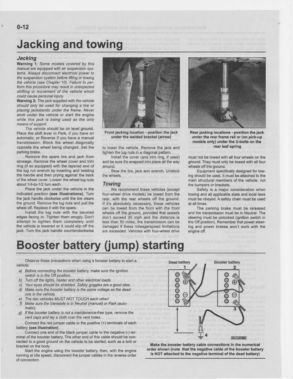
0-12 Jacking and towing Jacking Warning l: Some modelscoveredby this manual are equipped withair suspenslon sys- tems.Always disconnect electrical power to fhe suspenslon system before liftingor towing the vehicle (see Chapter 10). Failure to per- form thisprocedure may resultin unexpected shiftingor movement of the vehicle which couldcausepersonal injury. Warning 2: The jack supplied with the vehicle shouldonly be usedfor changing a tire or placing jackstands under the frame. Never work under the vehicleor start the engine while this jack is being used as the only means of support. The vehicle should be on level ground. Place the shiftlever in Park, if you have an automatic, or Reverse if you havea manual transmission. Blockthe wheeldiagonally opposite the wheelbeing changed. Set the parking brake. Remove the sparetire and jack from stowage. Remove the wheel cover andtrim ring(if so equipped) withthe tapered endof the lug nut wrench by inserting and twisting the handle andthenprying against the back ofthe wheel cover. Loosen thewheel lug nuts about 1 I 4-to-1 12 tum each. Place the jack under the vehicle in the indicated position (see illustrations). Turn the jack handle clockwise until the tire clears theground. Remove the lugnuts andpull the wheel off.Replace it with the spare. Install the lug nuts with the beveled edges facing in. Tighten themsnugly. Don't attempt to tighten them completely until the vehicle is lowered or it could slip off the jack.Turnthe jack handle counterclockwise Front jacking locatlon - positlonthe jack underthe weldedbracket (anow) to lower the vehicle. Remove the jack and tighten the lugnuts in a diagonal paftem. Install the cover (and trimring, if used) andbe sure it'ssnapped intoplace all theway around. Stow the tire, jack andwrench. Unblock thewheels. Towing We recommend thesevehicles (except four-wheel drive models) be towedfrom the rear,with the rear wheelsoff the ground, lf it's absolutely necessary, thesevehicles can be towed from the front with the front wheels off the ground, provided thatspeeds don't exceed 35 mph and the distance,is lessthan50 miles; the transmission can be damaged if these mileage/speed limitations are exceeded. Vehicles withfour-wheel drive Rear jacking locatlons - poaitlon the jack underthe rearframerall or (on plck-up models only) underthe U.boltson the rear leaf spring must not be towed withall fourwheels on the ground. They must only betowed with allfour wheels ofi theground. Equipment specifically designed for tow- ingshould be used. lt must be attached to the main structural members of the vehicle, not the bumpers or brackets. Safety is a majorconsideration when towing and all applicable state and local laws must be obeyed. A safety chain must be used at alltimes. The parking brake must be released andthetransmission must be in Neutral. The steering mustbe unlocked (ignition switch in the Offposition). Remember thatpower steer- ing and powerbrakes won't work with the engine ofi. Booster battery fiump) starting Observe these precautions when using a booster battery to start a vehicle: a) Before connecting the booster baftery, ma4esure the ignition switch is in the Off position. b) Tum otr the lights, heater and otherelectical loads. c) Yaureyes should be shielded. Safety goggles are a goodidea. d) Make sure the booster baftery is the same voftage as the dead onein the vehicle. e) The two vehicles MUST NOT TQUCH each other! f) Make sure the transaxlq is in Neutral (manual) or Park(auto- matic). g) lf the booster baftery is not a maintenance-free type,remove the ventcaps andlay a cloth over the ventholes. Connect the red jumper cable to the positive (+)terminals of each battery (seeillustration). Connect oneendof the black jumper cable to the negative C) ter- minal of the booster baftery. Theother endof thiscable should be con- nected to a goodground on the vehicle to be started, such as a boltor bracket on the body. Start the engine using the booster battery, then, withthe engine running at idle speed, disconnect the jumper cables inthereverse order of connection. Make the boosterbattery cableconnectione In the numerical ordershown (note that the negative cableof the boosterbatiery is NOT attached to the negative teminal of the deadbattery) PALMTREESALES1967 - NO RESALE
This manual is a comprehensive guide for the 2002-2003 Ford F-150 Service & Repair Manual, offering complete technical details directly from the manufacturer. Designed for both professional mechanics and DIY enthusiasts, it provides in-depth information on the maintenance and repair of your Ford F-150.
Written by a team of skilled mechanics, the manual includes:
High-quality diagrams and equipment illustrations
Detailed procedures for diagnostics, repairs, and maintenance
Full mechanical and technical specifications
Step-by-step guides for introductory mechanics
Information on equipment elevation, collision repairs, and part descriptions
Guidance on products, supplies, and painting techniques
With instant access to the full manual, you can print each section as needed. If additional information is required, customer support is ready to assist with any queries.
Utilize the internet for access to comprehensive, cost-effective information without the need for printed books or shipping. Begin your maintenance and repair projects without delay using this essential service and repair manual for your 2002-2003 Ford F-150.