

2012-2014 Ford Escape Service & Repair Manual
What's Included?
Fast Download Speeds
Online & Offline Access
Access PDF Contents & Bookmarks
Full Search Facility
Print one or all pages of your manual
Symbols Glossary
Symbols are used inside the graphics and in the text area to enhance the information display.
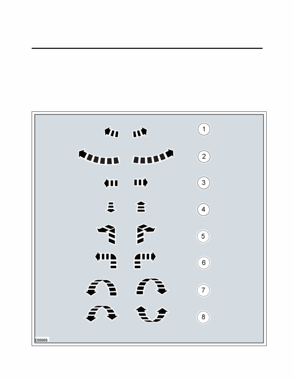
Movement Symbols
Movement symbols provide detailed information to a required component movement. These component
movements can be rotational or 1-3 dimensional movements.
100-00 General Information 2013 - 2014 Escape
Description and Operation Procedure revision date: 04/3/2013
Page 1 of 33
2014-04-30 file://C:\TSO\tsocache\VDTOM_1168\SDZ~us~en~file=SDZG1615041.HTM~gen~ref....
Turn Symbols
Turn symbols are used to provide further information on the direction or angle of component turns.
Item
Part
Number Description
1 — Minor component movement
clockwise/counterclockwise
2 — Major component movement
clockwise/counterclockwise
3 — Component movement to the left/right/up/down
4 — Component movement towards/away
5 — 3 dimensional component movement
6 — 2 dimensional component movement
7 — 3 dimensional component rotation
8 — 3 dimensional component cycling
Page 2 of 33
2014-04-30 file://C:\TSO\tsocache\VDTOM_1168\SDZ~us~en~file=SDZG1615041.HTM~gen~ref....
tomsn048@gmail.com
Item
Part
Number Description
1 — Turn the component clockwise through 45°
2 — Turn the component counterclockwise through 45°
3 — Turn the component clockwise through 90°
4 — Turn the component counterclockwise through 90°
5 — Turn the component clockwise through 180°
6 — Turn the component counterclockwise through 180°
7 — Turn the component clockwise through 2 complete
Page 3 of 33
2014-04-30 file://C:\TSO\tsocache\VDTOM_1168\SDZ~us~en~file=SDZG1615041.HTM~gen~ref....

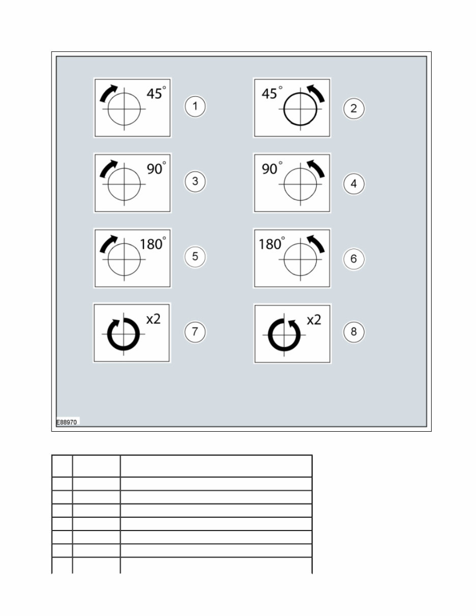
Steering Wheel Symbols
Steering wheel symbols are used to provide further information to a required steering wheel position or
steering column lock status.
turns
8 — Turn the component counterclockwise through 2
complete turns
Page 4 of 33
2014-04-30 file://C:\TSO\tsocache\VDTOM_1168\SDZ~us~en~file=SDZG1615041.HTM~gen~ref....
tomsn048@gmail.com
Part
Page 5 of 33
2014-04-30 file://C:\TSO\tsocache\VDTOM_1168\SDZ~us~en~file=SDZG1615041.HTM~gen~ref....
Body Types
Body type symbols are used to identify different body configurations.
Item Number Description
1 — Steering wheel in straight ahead position
2 — Steering column lock locked
3 — Steering column lock unlocked
4 — Turn the steering wheel to the 90° left position
5 — Turn the steering wheel to the 90° right position
6 — Turn the steering wheel to the left-hand end position
7 — Turn the steering wheel to the right-hand end
position
Page 6 of 33
2014-04-30 file://C:\TSO\tsocache\VDTOM_1168\SDZ~us~en~file=SDZG1615041.HTM~gen~ref....
tomsn048@gmail.com
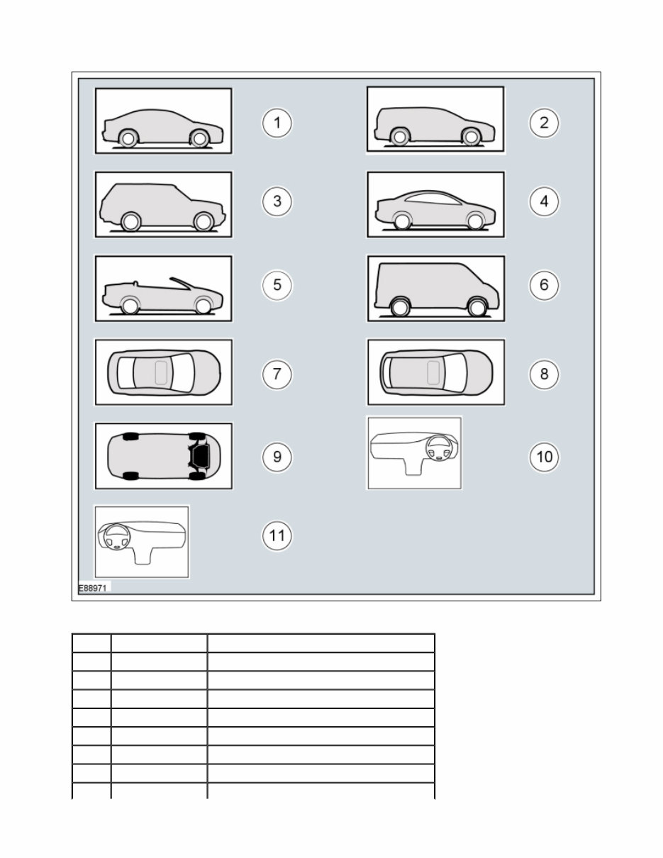
Item Part Number Description
1 — 3, 4, 5-door body style
2 — Wagon body style
3 — Sports utility vehicle body style
4 — Coupe body style
5 — Convertible body style
6 — Van body style
7 — 3, 4, 5-door body style - Top View
Page 7 of 33
2014-04-30 file://C:\TSO\tsocache\VDTOM_1168\SDZ~us~en~file=SDZG1615041.HTM~gen~ref....

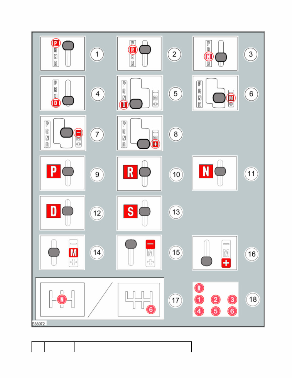
Gearshift lever and selector lever position symbols
Gearshift lever and selector lever position symbols are used to show the lever position that is required to be
selected to carry out a procedure step.
8 — Wagon body style - Top View
9 — Underview
10 — Right-hand drive (RHD) vehicle
11 — Left-hand drive (LHD) vehicle
Page 8 of 33
2014-04-30 file://C:\TSO\tsocache\VDTOM_1168\SDZ~us~en~file=SDZG1615041.HTM~gen~ref....
tomsn048@gmail.com
Part
Page 9 of 33
2014-04-30 file://C:\TSO\tsocache\VDTOM_1168\SDZ~us~en~file=SDZG1615041.HTM~gen~ref....
Screwdriver symbols
The screwdriver symbols are used to show which screwdriver bit is recommended to carry out a procedure
step.
Item Number Description
1 — Replaced by symbol 9
2 — Replaced by symbol 10
3 — Replaced by symbol 11
4 — Replaced by symbol 12
5 — Replaced by symbol 12
6 — Replaced by symbol 14
7 — Replaced by symbol 15
8 — Replaced by symbol 16
9 — Set the selector lever to the park (P) position
10 — Set the selector lever to the reverse ( R ) position
11 — Set the selector lever to the neutral (N) position
12 — Set the selector lever to the drive (D) position
13 — Set the selector lever to the drive (S) position
14 — Set the selector lever to the drive (M) position
15 — Set the selector lever to the drive (-) position
16 — Set the selector lever to the drive (+) position
17 — Set the gearshift lever to the neutral (N) position
18 — Further gearshift lever positions that may appear in
illustrations
Page 10 of 33
2014-04-30 file://C:\TSO\tsocache\VDTOM_1168\SDZ~us~en~file=SDZG1615041.HTM~gen~ref....
tomsn048@gmail.com
You're Reading a Preview
What's Included?
Fast Download Speeds
Online & Offline Access
Access PDF Contents & Bookmarks
Full Search Facility
Print one or all pages of your manual
$31.99
$41.99
Viewed 50 Times Today


Secure transaction
What's Included?
Fast Download Speeds
Online & Offline Access
Access PDF Contents & Bookmarks
Full Search Facility
Print one or all pages of your manual
$31.99
$41.99
Discover the comprehensive 2012-2014 Ford Escape Service & Repair Manual!
- Access a complete guide for maintaining and repairing your Ford Escape spanning from 2012 to 2014.
- Beneficial for professional mechanics and DIY enthusiasts alike.
- Comprises detailed instructions, diagrams, and illustrations to assist with every repair task.
- Covers an extensive array of topics, encompassing the engine, electrical system, brakes, suspension, and more.
- Compatible with the following Ford Escape models:
- 2012 Ford Escape
- 2013 Ford Escape
- 2014 Ford Escape
Whether it's routine maintenance or a complex repair, this manual is your go-to resource. Invest in the 2012-2014 Ford Escape Service & Repair Manual to ensure your Escape operates seamlessly for years to come.


