FOREWORD The information contained in this service manual has been prepared for the professional automotive tech- nician involved in daily repair operations. This manual does not cover theory of operation, which is addressed in service training material. Information describing the operation and use of standard and optional equipment is included in the Owner's Manual provided with the vehicle. Information in this manual is divided into groups. These groups contain general information, diagnosis, testing, adjustments, removal, installation, disassembly,' and assembly procedures for systems and components. To assist in locating a group title page, use the Group Tab Locator on the following page. The solid bar after the group title is aligned to a solid tab on the first page of each group. The first page of the group has a contents section that lists major topics within the group.. I f you are not sure which Group contains the infor- mation you need, look up the Component/System in the alphabetical index located in the rear of this manual. A Service Manual Comment form is included at the rear of this manual. Use the form to provide Chrysler Corporation with your comments and suggestions. Tightening torques are provided as a specific value throughout this manual. This value represents the midpoint of the acceptable engineering torque range for a given fastener application. These torque values are intended for use in service assembly and installation procedures using the correct OEM fasteners. When replacing fasteners, always use the same type (part number) fastener as removed. Chrysler Corporation reserves the right to change testing procedures, specifications, diagnosis, repair methods, or vehicle wiring at any time without prior notice or incurring obligation.
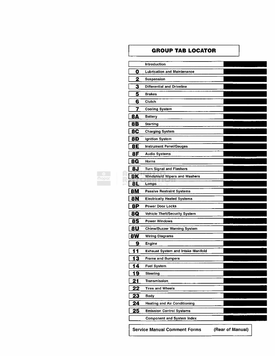
GROUP TAB LOCATOR 8G 8P Introduction Lubrication and Maintenance 2 Suspension Differential and Driveline Brakes 6 Clutch 7 Cooling System 8A Battery 8B Starting 80 Charging System 8P Ignition System 8E I nstrument Panel/Gauges 8F Audio Systems Horns 8 J Turn Signal and Flashers 8IN Electrically Heated Systems Power Door Locks 8Q Vehicle Theft/Security System 8S Power Windows 80 Chime/Buzzer Warning System 8W Wiring Diagrams 9 Engine SiC Windshield Wipers and Washers 8L Lamps 811 Passive Restraint Systems 1 j Exhaust System and Intake Manifold i 3 Frame and Bumpers j 4 Fuel System 19 Steering Transmission 22 Tires and Wheels 23 Body 24 Heating and Air Conditioning 25 Emission Control Systems Component and System Index Service Manual Comment Forms (Rear of Manual)
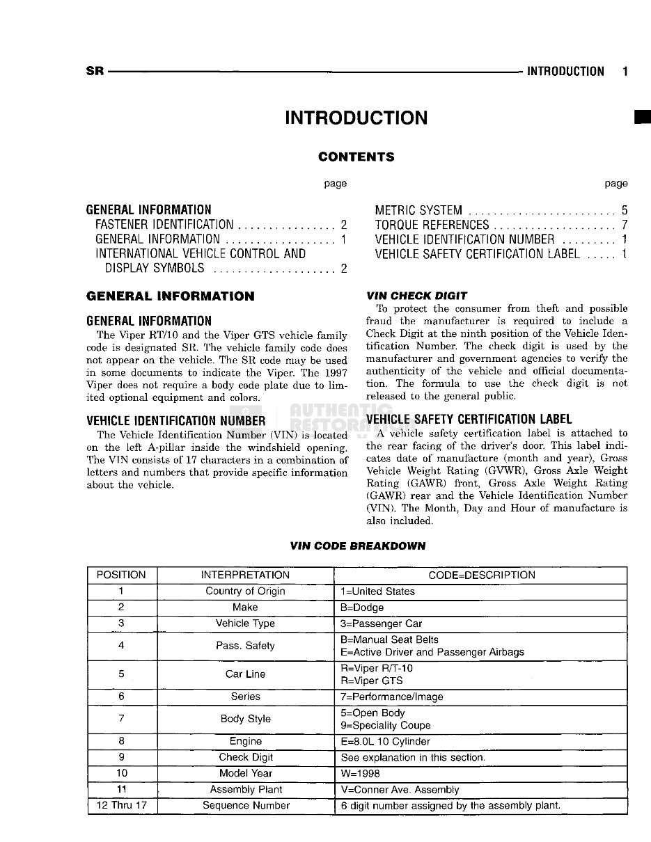
SR INTRODUCTION 1 INTRODUCTION CONTENTS page GENERAL INFORMATION FASTENER IDENTIFICATION 2 GENERAL INFORMATION 1 INTERNATIONAL VEHICLE CONTROL AND DISPLAY SYMBOLS 2 page METRIC SYSTEM 5 TORQUE REFERENCES 7 VEHICLE IDENTIFICATION NUMBER 1 VEHICLE SAFETY CERTIFICATION LABEL 1 GENERAL INFORMATION GENERAL INFORMATION The Viper RT/10 and the Viper GTS vehicle family code is designated SR. The vehicle family code does not appear on the vehicle. The SR code may be used in some documents to indicate the Viper. The 1997 Viper does not require a body code plate due to lim- ited optional equipment and colors. VEHICLE IDENTIFICATION NUMBER The Vehicle Identification Number (VIN) is located on the left A-pillar inside the windshield opening. The VIN consists of 17 characters in a combination of letters and numbers that provide specific information about the vehicle. VIM CHECK mmiT To protect the consumer from theft and possible fraud the manufacturer is required to include a "Check Digit at the ninth position of the Vehicle Iden- tification Number. The check digit is used by the manufacturer and government agencies to verify the authenticity of the vehicle and official documenta- tion. The formula to use the check digit is not released to the general public. VEHICLE SAFETY CERTIFICATION LABEL A vehicle safety certification label is attached to the rear facing of the driver's door. This label indi- cates date of manufacture (month and year), Gross Vehicle Weight Rating (GVWR), Gross Axle Weight Rating (GAWR) front, Gross Axle Weight Rating (GAWR) rear and the Vehicle Identification Number (VIN). The Month, Day and Hour of manufacture is also included. VIM CODE BREAKDOWN POSITION INTERPRETATION CODE=DESCRIPTION 1 Country of Origin 1-United States 2 Make B=Dodge 3 Vehicle Type 3=Passenger Car 4 Pass. Safety B=Manual Seat Belts E=Active Driver and Passenger Airbags 5 Car Line R=Viper R/T-10 R=Viper GTS 6 Series 7=Performance/lmage 7 Body Style 5=Open Body 9=Speciality Coupe 8 Engine E=8.0L 10 Cylinder 9 Check Digit See explanation in this section. 10 Model Year W=1998 11 Assembly Plant V=Conner Ave. Assembly 12 Thru 17 Sequence Number 6 digit number assigned by the assembly plant.
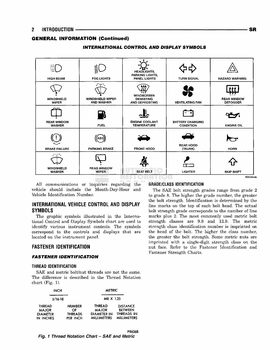
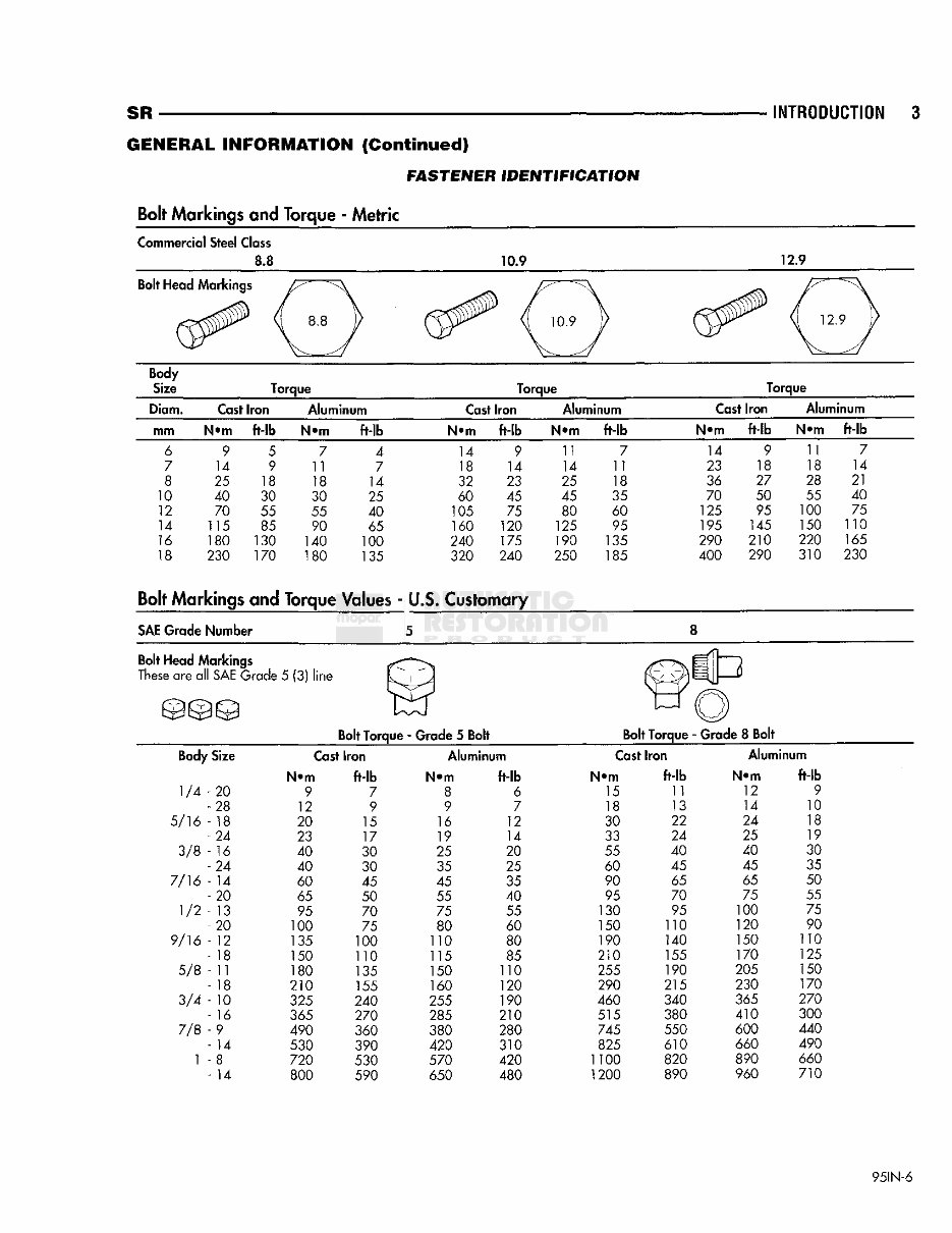
2 INTRODUCTION GENERAL INFORMATION (Continued) INTERNATIONAL CONTROL AND DISPLAY SYMBOLS SR 10 HIGH BEAM tp FOG LIGHTS HEADLIGHTS, PARKING LIGHTS, PANEL LIGHTS TURN SIGNAL A HAZARD WARNING WINDSHIELD WIPER WINDSHIELD WIPER AND WASHER WINDSCREEN DEMISTING AND DEFROSTING VENTILATING FAN LuD REAR WINDOW DEFOGGER CD i REAR WINDOW WASHER FUEL ENGINE COOLANT TEMPERATURE BATTERY CHARGING CONDITION ENGINE OIL (0) BRAKE FAILURE (0) PARKING BRAKE FRONT HOOD <&> REAR HOOD (TRUNK) HORN r'Y^» WINDSHIELD WASHER REAR WINDOW WIPER A SEAT BELT 1 I 1 LIGHTER SKIP SHIFT 80b34eab All communications or inquiries regarding the vehicle should include the Month-Day-Hour - and Vehicle Identification Number. INTERNATIONAL VEHICLE CONTROL AND DISPLAY SYMBOLS The graphic symbols illustrated in the Interna- tional Control and Display Symbols chart are used to identify various instrument controls. The symbols correspond to the controls and displays that are located on the instrument panel. FASTENER! IDENTIFICATION FASTENER IDENTIFICATION THREAD IDENTIFICATION SAE and metric bolt/nut threads are not the same. The difference is described in the Thread Notation chart (Fig. 1). INCH METRIC GRADE/CLASS IDENTIFICATION The SAE bolt strength grades range from grade 2 to grade 8. The higher the grade number, the greater the bolt strength. Identification is determined by the line marks on the top of each bolt head. The actual bolt strength grade corresponds to the number of line marks plus 2. The most commonly used metric bolt strength classes are 9.8 and 12.9. The metric strength class identification number is imprinted on the head of the bolt. The higher the class number, the greater the bolt strength. Some metric nuts are imprinted with a single-digit strength class on the nut face. Refer to the Fastener Identification and Fastener Strength Charts. 5/16-18 THREAD NUMBER MAJOR OF DIAMETER THREADS IN INCHES PER INCH M8 X 1.25 THREAD DISTANCE MAJOR BETWEEN DIAMETER IN THREADS IN MILLIMETERS MILLIMETERS PR606B Fig. 1 Thread Notation Chart - SAE and Metric
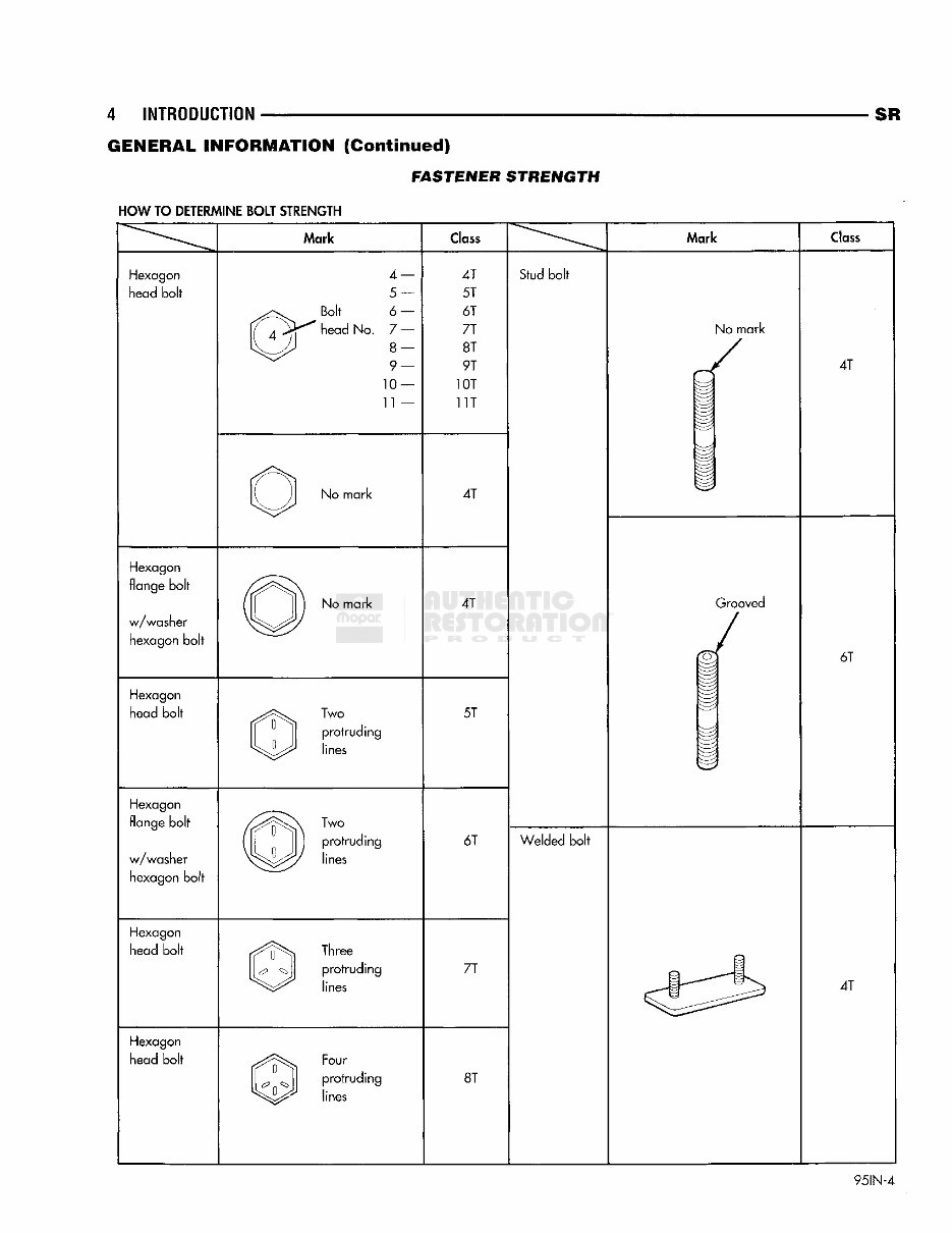
4 INTRODUCTION SR GENERAL INFORMATION (Continued) FASTENER STRENGTH HOW TO DETERMINE BOLT STRENGTH Mark CI lass Mark Class Hexagon head bolt Hexagon flange bolt w / washer hexagon bolt Hexagon head bolt Hexagon flange bolt w / washer hexagon bolt Hexagon head bolt Hexagon head bolt 4- 5- Bolt 6 - head No. 7 - 8- 9- 10- 11 - No mark No mark Two protruding lines Two protruding lines Three protruding Four l^n^lj P r o t r u d i n 9 lines 4T 51 61 71 8T 9T 10T 1 IT 4T 4T 51 61 71 81 Stud bolt Welded bolt No mark 4T Grooved 61 41 95IN-4
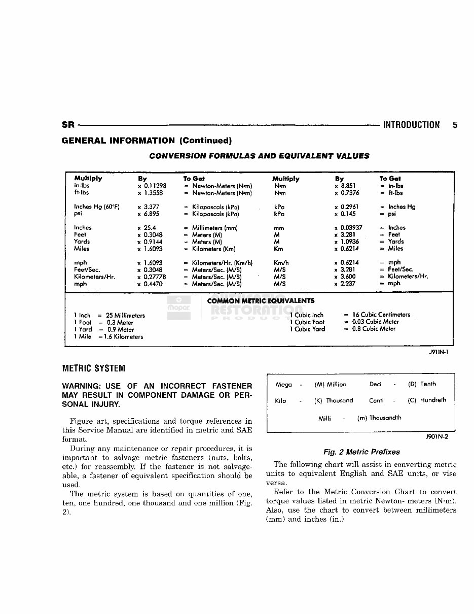
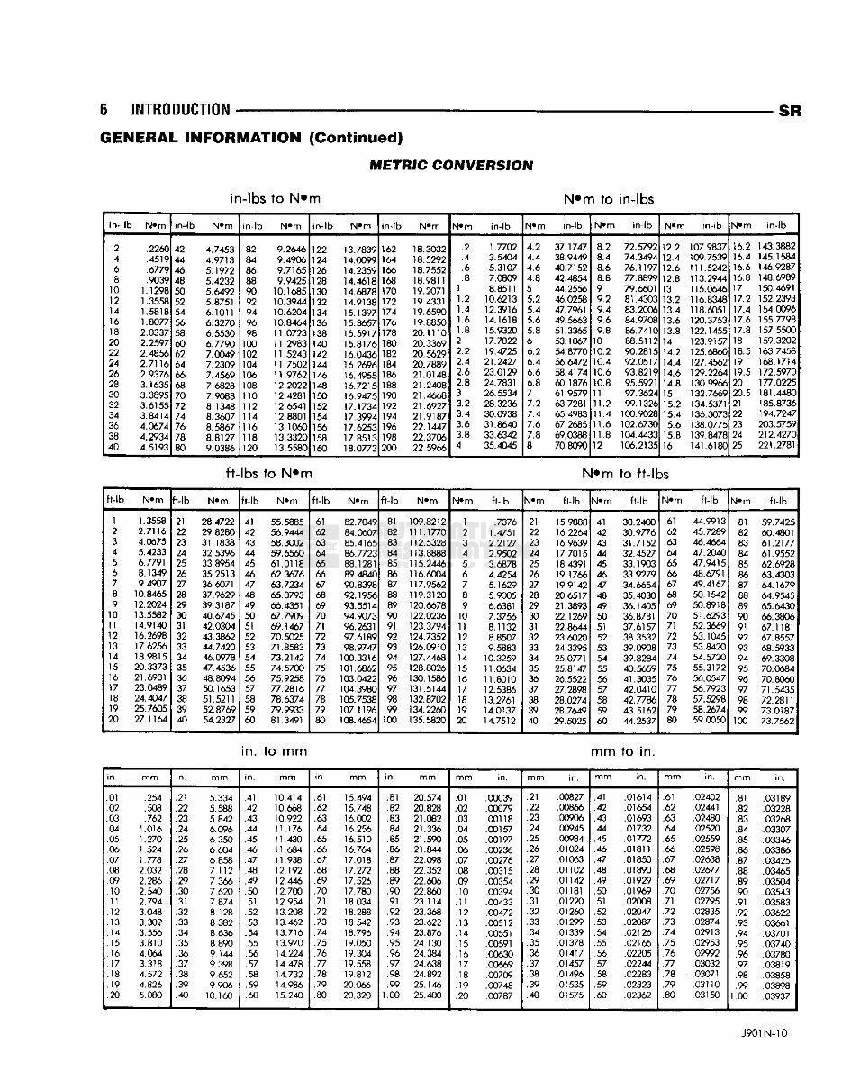
SR INTRODUCTION GENERAL INFORMATION (Continued) CONVERSION FORMULAS AND EQUIVALENT VALUES Multiply By To Get Multiply By To Get in-lbs x 0.11298 = Newton-Meters (N«m) N>m x 8.851 = in-lbs fMbs x 1.3558 = Newton-Meters (N»m) N*m x 0.7376 = ft-lbs Inches Hg (60°F) x 3.377 SB Kilopascals (kPa) IcPa x 0.2961 = Inches Hg psi x 6.895 = Kilopascals (kPa) kPa x 0.145 - psi Inches x 25.4 SB Millimeters (mm) mm x 0.03937 = Inches Feet x 0.3048 = Meters (M) M x 3.281 = Feet Yards x 0.9144 3S Meters (M) M x 1.0936 = Yards Miles x 1.6093 = Kilometers (Km) Km x 0.6214 = Miles mph x 1.6093 Kilometers/Hr. (Km/h) Km/h x 0.6214 = mph Feet/Sec. x 0.3048 ss Meters/Sec. (M/S) M/S x 3.281 = Feet/Sec. Kilometers/Hr. x 0.27778 s Meters/Sec. (M/S) M/S x 3.600 = Kilometers/Hr. mph x 0.4470 = Meters/Sec. (M/S) M/S x 2.237 » mph COMMON METRIC EQUIVALENTS 1 Inch = 25 Millimeters 1 Cubic Inch ~ 16 Cubic Centimeters 1 Foot = 0.3 Meter 1 Cubic Foot = 0.03 Cubic Meter 1 Yard = 0.9 Meter 1 Cubic Yard = 0.8 Cubic Meter 1 Mile = 1.6 Kilometers J91IN-1 iETiiC SYSIEi WARNING; USE MAY RESULT IN SONAL INJURY. OF AN INCORRECT FASTENER COMPONENT DAMAGE OR PER- Figure art, specifications and torque references in this Service Manual are identified in metric and SAE format. During any maintenance or repair procedures, it is important to salvage metric fasteners (nuts, bolts, etc.) for reassembly. If the fastener is not salvage- able, a fastener of equivalent specification should be used. The metric system is based on quantities of one, ten, one hundred, one thousand and one million (Fig. 2). . Mega - (M) Million Deci (D) Tenth Kilo (K) Thousand Cent! (C) Hundreth Milli (m) Thousandth J901N-2 Fig. 2 Metric Prefixes The following chart will assist in converting metric units to equivalent English and SAE units, or vise versa. Refer to the Metric Conversion Chart to convert torque values listed in metric Newton- meters (N-m). Also, use the chart to convert between millimeters (mm) and inches (in.)
Get your hands on the 1998 Dodge Viper Service and Repair Manual, your go-to resource for fixing vehicle issues. Whether you're a professional mechanic or a DIY enthusiast, these manuals provide comprehensive instructions and procedures to tackle car problems. The manual includes technical data, diagrams, a complete list of car parts, and images, making it easy for even novice mechanics to follow along. It covers various sections such as maintenance, engine, control system, mechanical, fuel service specifications, and much more. The manual is available in .PDF format for easy access and printing. It's compatible with Windows and Mac operating systems. With this manual, you can save time and money by learning to repair different parts of your car on your own. Keep it handy on your PC and print the necessary pages whenever needed. Take charge of your car repairs with this comprehensive manual.
Complete step-by-step instructions
Diagrams and illustrations
Wiring schematics and specifications
Windows Vista32 and 64, XP, ME, 98, NT, 2000 compatible