2022 RAM 1500 Pickup 3.0L V6 Turbo Diesel Gen 3 Service & Repair Manual
What's Included?
Lifetime Access
Fast Download Speeds
Online & Offline Access
Access PDF Contents & Bookmarks
Full Search Facility
Print one or all pages of your manual
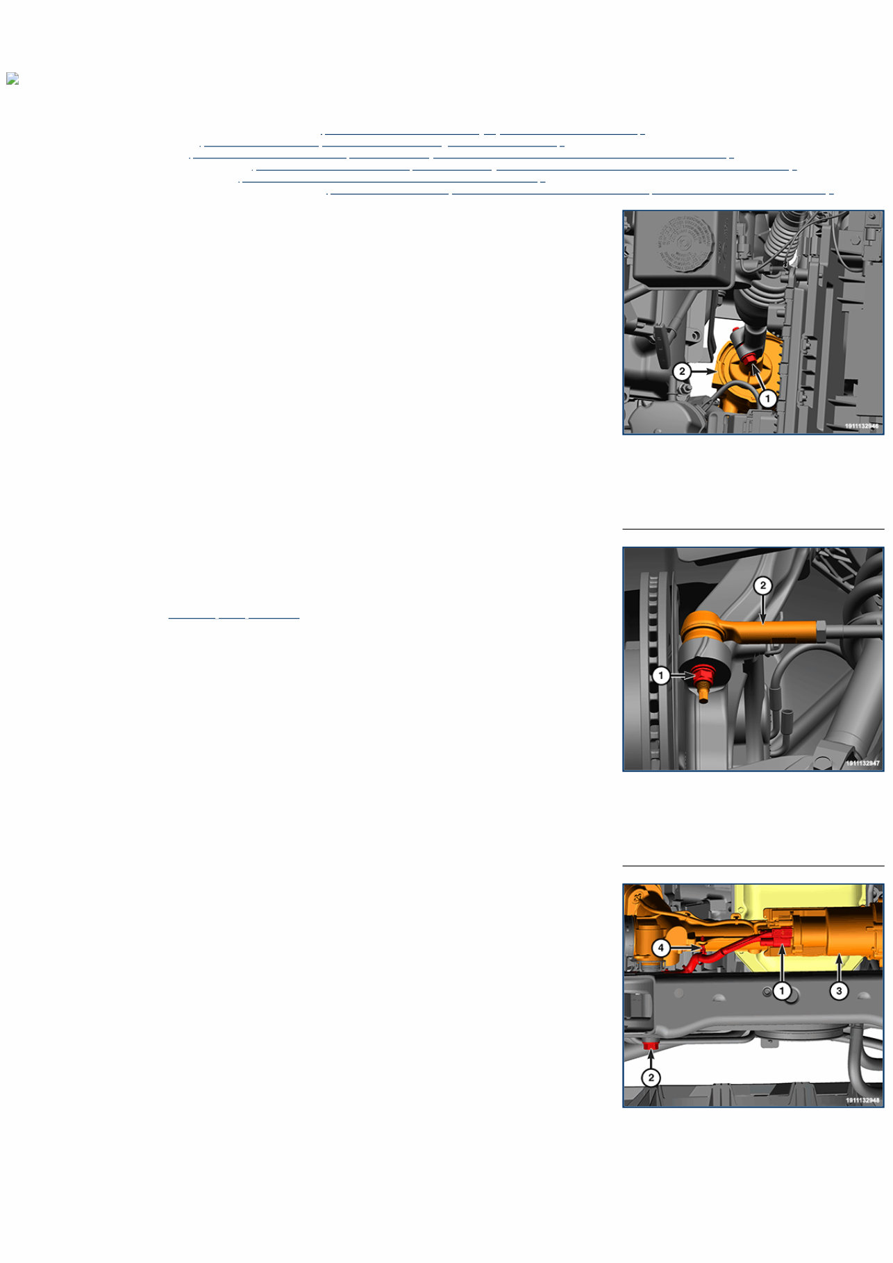
1 - Steering Gear Pinch Bolt 2 - Steering Gear 1 - Knuckle Nut 2 - Tie Rod End 1 - Wire Harness Connector 2 - Steering Gear Mounting Bolts 3 - EPS Module 19 - Steering / Gear / Removal and Installation STEERING GEAR Special Tools: Click to display a list of tools used in this procedure REMOVAL 1. Disconnect and isolate the negative battery cable(s) (Refer to 08 - Electrical/Battery System/Standard Procedure) . 2. Raise and support the vehicle (Refer to 04 - Vehicle Quick Reference/Hoisting/Standard Procedure) . 3. Remove the front skid plate (Refer to 13 - Frame and Bumpers/Under Body Protection/PLATE, Skid, Front/Removal and Installation) , if equipped. 4. Remove the front suspension skid plate (Refer to 13 - Frame and Bumpers/Under Body Protection/PLATE, Skid, Front/Removal and Installation) , if equipped. 5. Remove the tire and wheel assembly (Refer to 22 - Tires and Wheels/Removal and Installation) . 6. For TRX models, remove the left front shock absorber (Refer to 02 - Front Suspension/Front/SHOCK ABSORBER, Suspension/Removal and Installation) . NOTE: Do not start to remove (or break free) the pinch bolt with an impact wrench. 7. Remove and DISCARD the intermediate shaft to steering gear pinch bolt and disconnect the intermediate shaft from the steering gear. 8. Remove the tie rod end to knuckle nut on both sides. NOTE: Right side shown, left side similar. 9. Using ball joint remover Remover, Ball Joint 9360 , separate the outer tie rod end from the steering knuckle. 10. Disconnect the wire harness connectors from the Electronic Power Steering (EPS) module. 11. Disengage the wire harness routing clip from the steering gear. 12. Remove and DISCARD the two steering gear mounting bolts and washers. 13. Remove the steering gear assembly from the vehicle.
4 - Wire Harness Routing Clip INSTALLATION Follow the removal procedure in reverse for general reassembly of the components on the vehicle. The steps listed below are calling out specific procedures that should be followed during installation. Install two NEW steering gear mounting bolts and washers and tighten to the proper (Torque Specifications) . Install the tie rod end to knuckle nuts and tighten to the proper (Torque Specifications) . Connect the intermediate steering shaft to the steering gear using a NEW intermediate shaft to steering gear pinch bolt and tighten to the proper (Torque Specifications) .
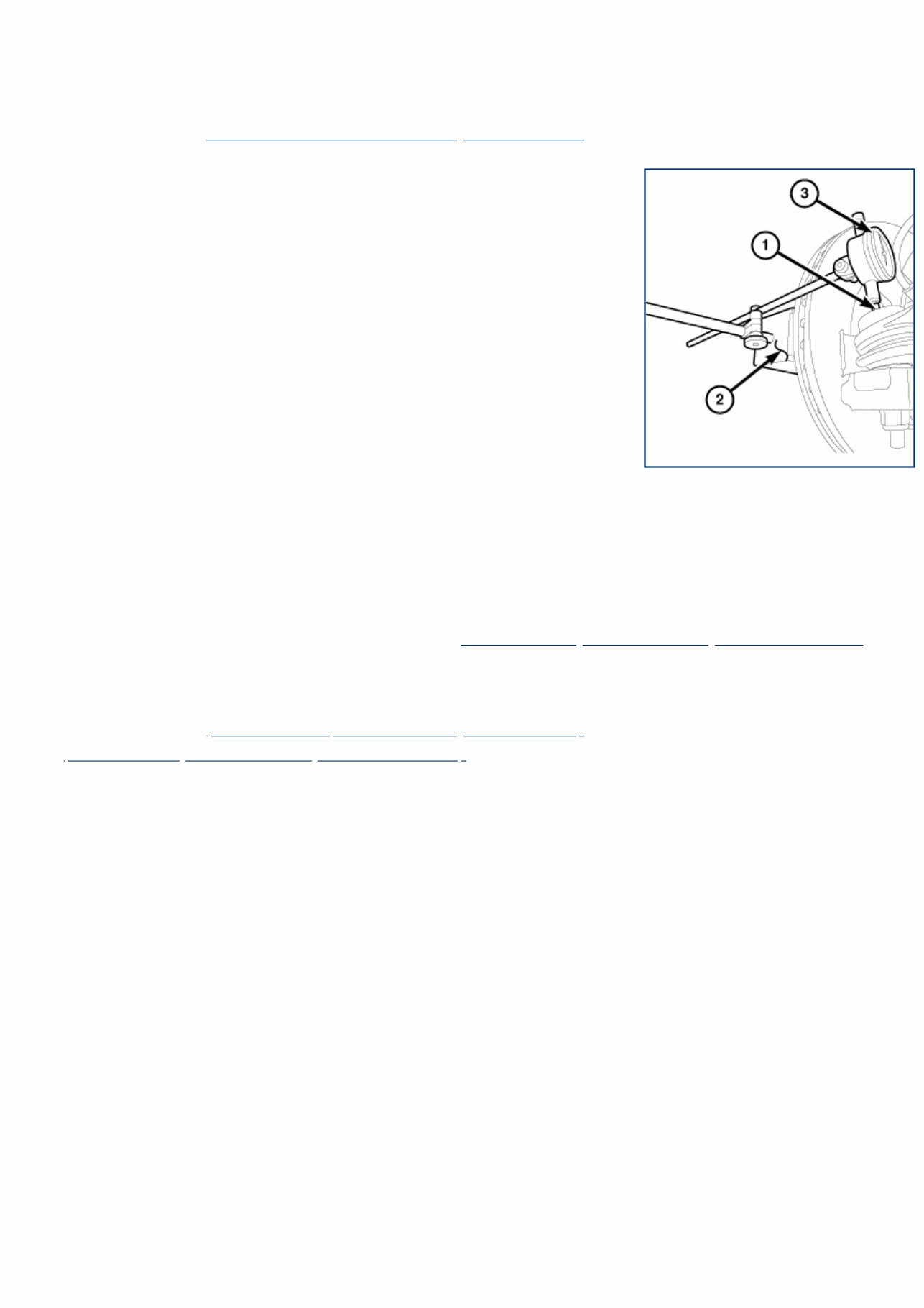
19 - Steering / Gear / TIE ROD, Steering / Diagnosis and Testing DIAGNOSIS AND TESTING OUTER TIE ROD 1. Raise and support the vehicle (Refer to 04 - Vehicle Quick Reference/Hoisting/Standard Procedure) . 2. Remove the front wheels. 3. Install two standard wheel mounting nuts, flat side to rotor, diagonally opposite to each on the rotor. 4. Attach a magnetic dial indicator (2) to the inside or outside of the brake rotor, then align the dial indicator's contact pointer (1) with the direction of the stud axis and touch the outer tie rod. 5. Zero the dial indicator (3). NOTE: When checking free-play, DO NOT rotate the tie rod. Just because a tie rod rotates easily does not mean that it is necessarily faulty. Using more than light hand pressure will result in a false reading. 6. Grasp the outer tie rod near the ball stud and attempt to move the tie rod straight up and down using light hand pressure (less than 10 lbs. of force). 7. Measure and record any tie rod free-play movement. 8. Remove the magnetic dial indicator. 9. Remove the standard wheel mounting nuts from the two studs. If the free-play in the tie rod exceeds 0.05 mm (.002 in.), replace the outer tie rod (Refer to 19 - Steering/Gear/TIE ROD, Steering/Removal and Installation) . If the free-play is less than 0.05 mm (.002 in.) at the outer tie rod check the inner tie rod for free-play. INNER TIE ROD 1. Raise and support the vehicle (Refer to 04 - Vehicle Quick Reference/Hoisting/Standard Procedure) . 2. Grasp the inner tie rod near the steering gear bellows and attempt to move the tie rod straight up and down. If any free-play is felt, replace the inner tie rod end (Refer to 19 - Steering/Gear/TIE ROD, Steering/Removal and Installation) . 3. Remove the support and lower the vehicle.
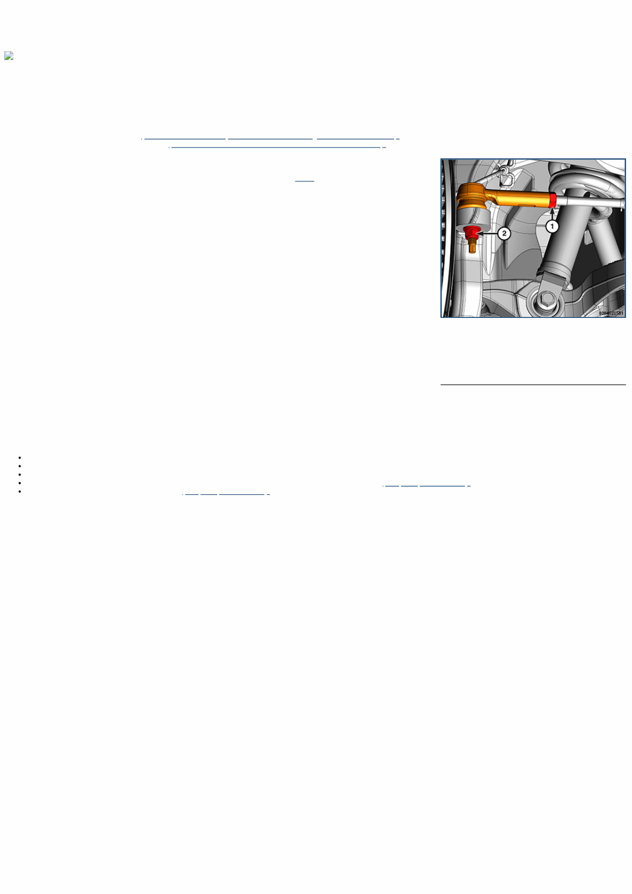
1 - Tie Rod Jam Nut 2 - Knuckle Nut 19 - Steering / Gear / TIE ROD, Steering / Removal and Installation OUTER TIE ROD Special Tools: Click to display a list of tools used in this procedure REMOVAL CAUTION: When loosening the jam nut and the rotating inner tie rod, use care not to twist the bellows at the inner tie rod. Remove the clamp at the inner tie rod and make sure the bellows moves freely before rotating the inner tie rod. 1. Raise and support the vehicle (Refer to 04 - Vehicle Quick Reference/Hoisting/Standard Procedure) . 2. Remove the tire and wheel assembly (Refer to 22 - Tires and Wheels/Removal and Installation) . 3. Loosen the tie rod jam nut. 4. Remove the tie rod end to knuckle nut from the ball stud. 5. Separate the tie rod ball stud from the knuckle with Ball Joint Remover 9360 . NOTE: Count number of turns when removing outer tie rod. This will give a good starting point when reassembling and when setting toe. 6. Unthread the outer tie rod end from the inner tie rod. INSTALLATION Follow the removal procedure in reverse for general reassembly of the components on the vehicle. The steps listed below are calling out specific procedures that should be followed during installation. Thread the outer tie rod end onto the inner tie rod, using the same number of threads as when removed. If a new tie rod end is to be installed, be certain the boot is properly lubricated. Clean all old grease and debris from the boot with a clean cloth. While holding the ball stud with a wrench, tighten the tie rod end to knuckle nut to the proper (Torque Specifications) . Tighten the tie rod jam nut to the proper (Torque Specifications) .
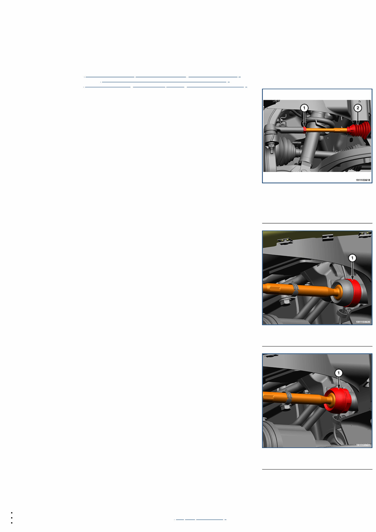
1 - Inner Tie Rod 2 - Inner Tie Rod Boot 1 - Steering Rack Bumper 1 - Inner Tie Rod 19 - Steering / Gear / TIE ROD, Steering / Removal and Installation INNER TIE ROD REMOVAL NOTE: Right side shown, left side similar. 1. Raise and support the vehicle (Refer to 04 - Vehicle Quick Reference/Hoisting - Standard Procedure) . 2. Remove the tire and wheel assembly (Refer to 22 - Tires and Wheels/Removal and Installation) . 3. Remove the outer tie rod end (Refer to 19 - Steering/Gear/TIE ROD, Steering/Removal and Installation) . 4. Remove the jam nut from the inner tie rod. 5. Remove the clamps for the inner tie rod boot. 6. Remove the boot and DISCARD. 7. Remove the steering rack bumper. 8. Remove the inner tie rod from the steering rack. INSTALLATION Follow the removal procedure in reverse for general reassembly of the components on the vehicle. The steps listed below are calling out specific procedures that should be followed during installation. Apply Mopar® Lock and Seal Adhesive or equivalent medium thread locker adhesive to the inboard end threads of the inner tie rod. Thread the inner tie rod to the steering rack and tighten to the proper (Torque Specifications) . Install a NEW inner tie rod end boot and clamp to the tie rod and rack.
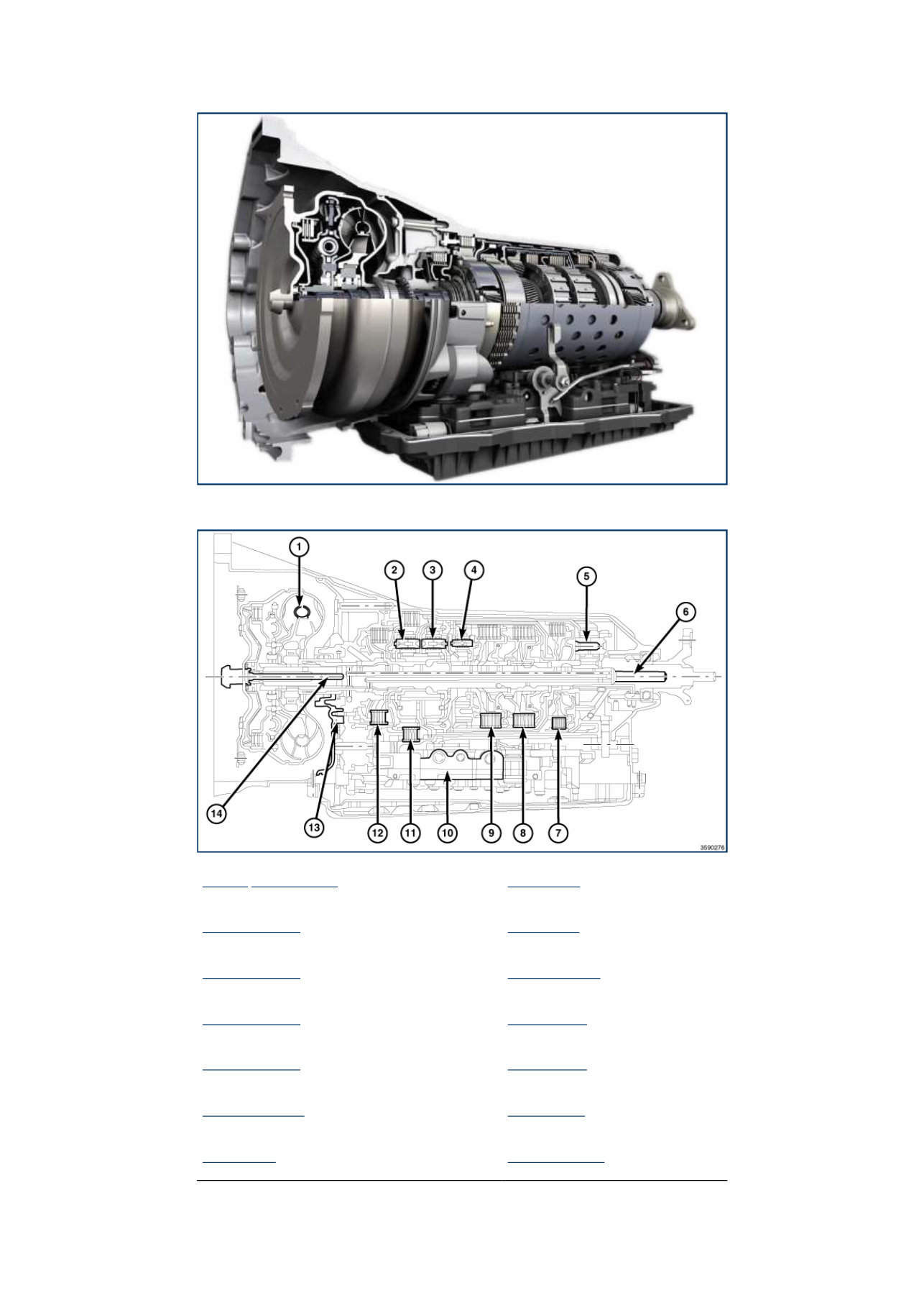
21 - Transmission and Transfer Case / Automatic - 8HP75 / Description DESCRIPTION AND OPERATION DESCRIPTION 1 - TORQUE CONVERTER 8 - C CLUTCH 2 - P1 PLANETARY 9 - E CLUTCH 3 - P2 PLANETARY 10 - VALVE BODY 4 - P3 PLANETARY 11 - B CLUTCH 5 - P4 PLANETARY 12 - A CLUTCH 6 - OUTPUT SHAFT 13 - OIL PUMP 7 - D CLUTCH 14 - INPUT SHAFT CAUTION: A unique transmission fluid has been developed for this transmission. This fluid is NOT compatible with ATF+4 or any other current FCA US LLC transmission fluid. For specifics about this unique fluid see FLUIDS, LUBRICANTS AND GENUINE PARTS. The transmission case is a single-piece unit. The starter pocket, cooler line fittings, and manual park release lever are located on the driver's side of the case. The transmission wire harness connector and oil fill plug are located on the passenger side of the case. The two-wheel drive model uses a flanged output shaft
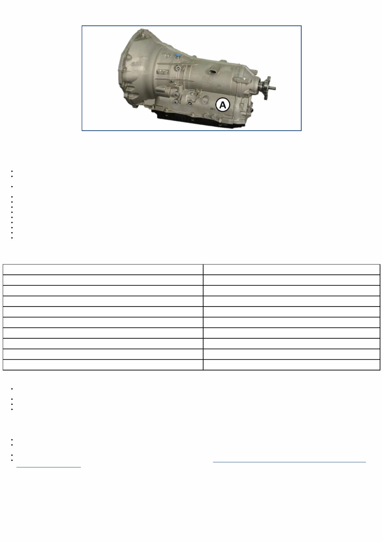
connection. The four-wheel drive model uses a sealed, externally-splined output shaft to form a dry connection between the adapter plate and the transfer case. Identification In the area of location (A) there are two barcodes and their corresponding alphanumeric codes. The top code identifies the COMPONENT TRACKING NUMBER. The bottom code identifies the PART NUMBER. OPERATION The 8HP75 is an electronic eight-speed automatic transmission. The Transmission Control Module Assembly (TCMA), which is integrated into the valve body, provides fully synchronized clutch-to-clutch shifting through four planetary gear sets. The TCMA includes a mounting plate that holds the Transmission Control Module (TCM) and a molded wiring harness for connection to various transmission sensors and solenoids. The valve body assembly contains all the sensors and solenoids required for operation, completely inside the transmission. Eight speeds allow the engine to maintain its optimal rpm range, increasing fuel economy and performance. Transmission control is performed by the TCM based on hard-wired and Controller Area Network (CAN ) bus signals from sensors and modules. The TCM receives driveability data from the Powertrain Control Module (PCM) and other modules over the CAN-Chassis (CAN-C) bus. The TCM also receives shift lever position information from the Electronic Shift Module (ESM) over a dedicated transmission CAN bus. The TCM processes this input data and controls operation of the torque converter clutch, park lock system, solenoid valves, and pressure regulating valve. The input and output speed sensors are Hall-effect sensors that measure shaft rotational speed. The input speed sensor is located at the top, near the center, of the of the TCMA and reads input shaft speed from the magnetic ring on the P2 carrier. The output speed sensor is located at the back of the TCMA and reads output shaft speed from the P4 carrier. GEAR RATIO 1st 5.000 2nd 3.200 3rd 2.143 4th 1.720 5th 1.313 6th 1.00 7th 0.823 8th 0.640 Reverse 3.478 FILTER SERVICE The 8HP75 has a conventional fluid sump design, however, the transmission oil filter is integrated into the transmission oil pan resulting in a lower profile for improved vehicle packaging. The transmission oil pan gasket is reusable providing it is not damaged during removal. If the gasket is damaged inspect the transmission oil pan for damage. Replace the transmission oil pan gasket or the transmission oil pan and gasket as an assembly. FLUID CHECK AND FILL A transmission fluid fill tube and indicator are not provided. All work is performed under the vehicle while raised on a hoist. In the event of a transmission shift quality concern, a fluid leak, or in conjunction with a transmission repair, the transmission fluid level must be validated and topped off as necessary. The procedure involves the use of a scan tool to monitor transmission fluid temperature. Specific service procedures are necessary to check and fill the transmission with fluid (Refer to 21 - Transmission and Transfer Case/Automatic/FLUID and FILTER/Standard Procedure) . Epicyclic Gear Sets
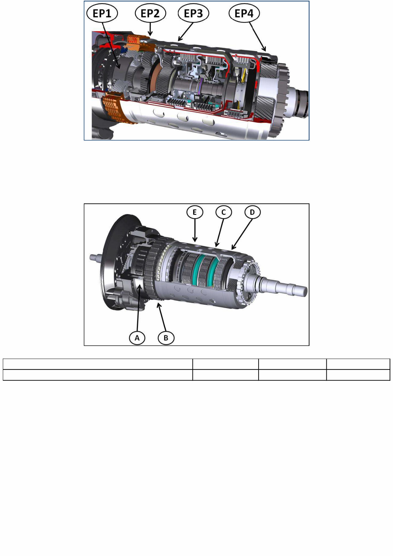
EP (1, 2, 3, 4) epicyclic gear train The 8 forward gears and reverse are implemented by connecting four single-arm epicyclic gear trains. The two front gear trains have a common sun gear, while the power is always output through the fourth epicyclic gear train planet carrier. Engagement Elements There are five engagement elements divided as follows: Brakes A B Clutches C D E Multiple-disc clutches C, D and E transmit the engine torque to the epicyclic gear train, while brakes A and B offload the engine torque to the transmission housing. The engagement elements are hydraulically closed. The fluid pressure compresses the disc pack to engage the clutch. When the hydraulic pressure decreases, the diaphragm spring pushes the piston into its rest position. The engagement elements serve to engage the gears under load without interrupting the traction force. For each gear, three engagement elements are always closed while two engagement elements will always remain open. Each open engagement element creates drag torque which allows an increase in transmission efficiency. Brakes
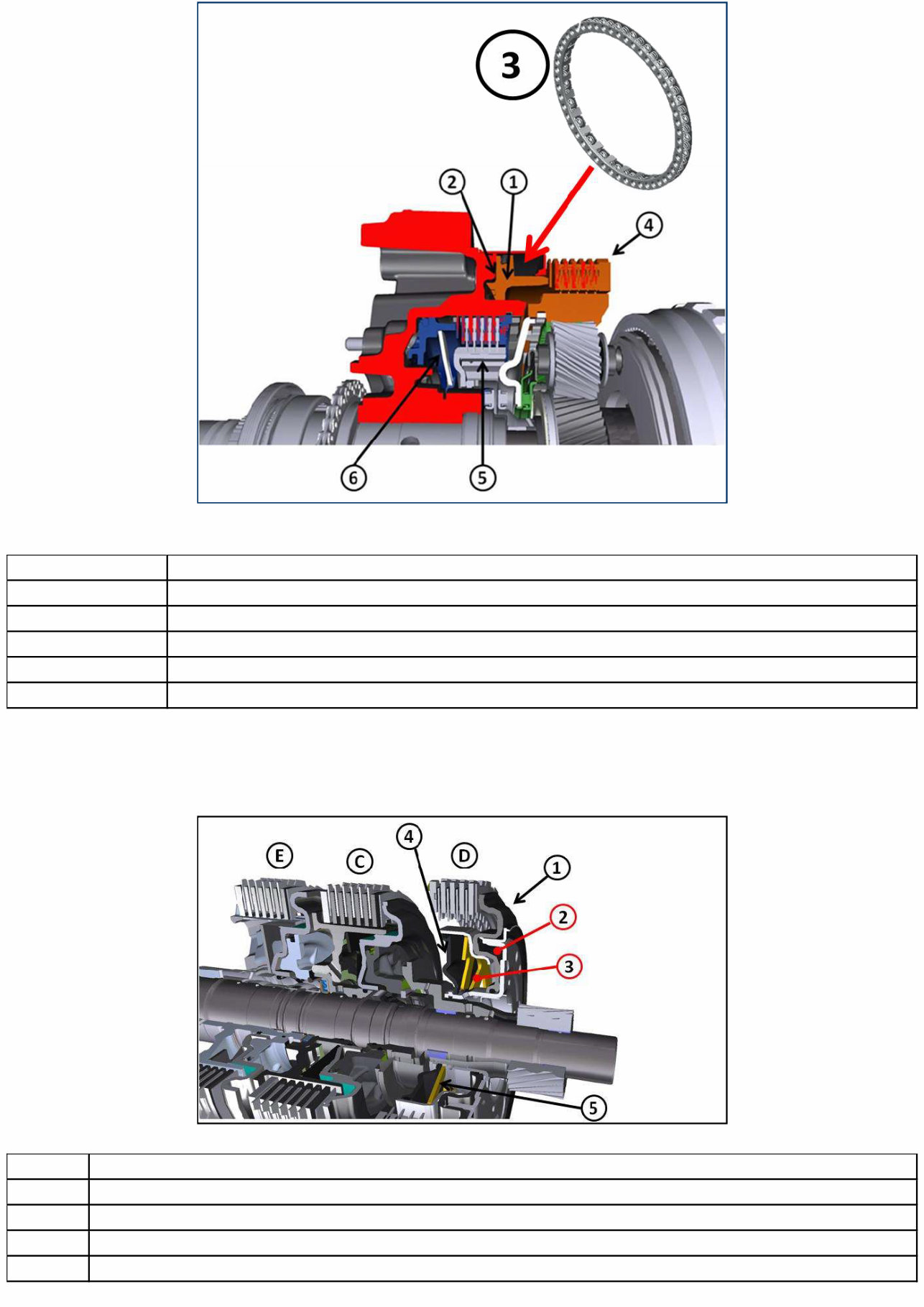
1 Brake B Piston 2 B1 Chamber 3 Return Spring 4 Brake B 5 Brake A 6 Return Spring Brake B has a spring pack to return the piston into position. Brake A has a diaphragm return spring. Clutches 1 Piston 2 Pressure chamber 3 Hydraulic compensation chamber 4 Diaphragm 5 Diaphragm spring The dynamic pressure of clutches C, D and E is compensated.
Keep Your 2022 RAM 1500 Pickup Running Smoothly And Efficiently With This Comprehensive Service And Repair Manual. Whether You'Re An Experienced Mechanic Or A Novice Diy Enthusiast, This Manual Contains All The Necessary Troubleshooting And Replacement Procedures Recommended By The Manufacturer.
With Step-By-Step Instructions, Clear Images, And Exploded-View Illustrations, You'Ll Have Everything You Need To Tackle Any Issue That May Arise With Your Vehicle. No More Searching Through Hundreds Of Pages Or Flipping Through Greasy, Torn, Or Lost Pages. This Manual Is Easily Accessible And User-Friendly, Making It A More Convenient Option Than Traditional Bound Manuals.
Compatible With Any Electronic Device, Including Pcs, Mac Computers, Smartphones, And Tablets, You Can Take This Manual With You Wherever You Go. No Internet Connection? No Problem. Simply Download And Save The Manual For Offline Use.
Regular Maintenance Is Crucial For Keeping Your Vehicle In Top Condition, And With This Manual, You'Ll Have The Knowledge And Resources To Do It Yourself. By Following The Manufacturer'S Recommended Procedures, You Can Save On Costly Repairs, Increase Your Vehicle'S Reliability, And Keep Your Repair Shop Visits At Bay.
Don'T Let Car Troubles Slow You Down. Get Your Hands On This 2022 RAM 1500 Pickup Service And Repair Manual And Keep Your Vehicle Running Like New.
Models Included:
2022 RAM 1500 Pickup
2022 RAM 1500 Classic Pickup
2022 RAM 1500 Rebel Trx
2022 RAM 1500 Limited Trx
2022 RAM 1500 Laramie Trx
Recently Viewed
5,521,897Happy Clients
2,594,462eManuals
1,120,453Trusted Sellers
15Years in Business
Price:
Actual Price:
2022 RAM 1500 Pickup 3.0L V6 Turbo Diesel Gen 3 Service & Repair Manual