2020 RAM 1500 Pickup 3.0L V6 Turbo Diesel Gen 3 Service & Repair Manual
What's Included?
Lifetime Access
Fast Download Speeds
Online & Offline Access
Access PDF Contents & Bookmarks
Full Search Facility
Print one or all pages of your manual
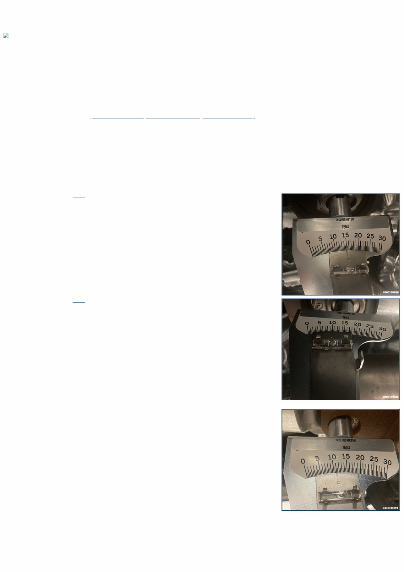
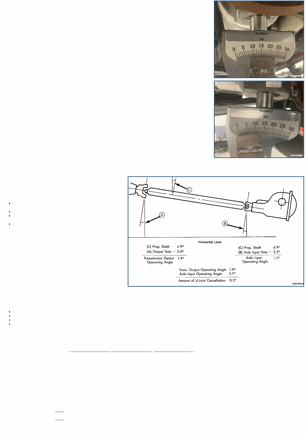
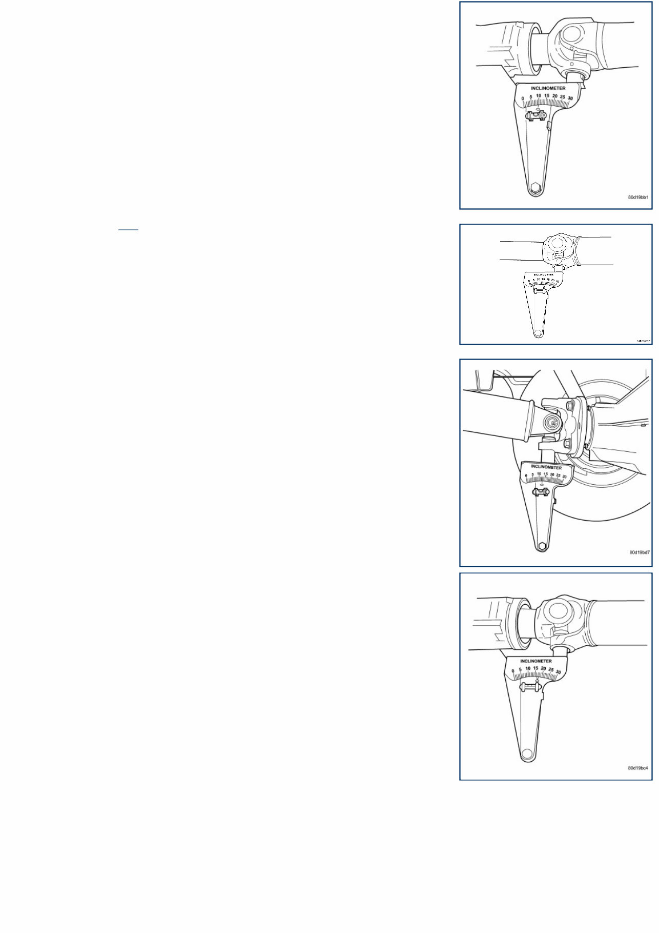
03 - Differential and Driveline / Driveshaft / Standard Procedure DRIVESHAFT ANGLE Special Tools: Click to display a list of tools used in this procedure ONE PIECE DRIVESHAFT This procedure applies to the front and rear driveshafts. NOTE: To obtain output angle (A) on the front driveshaft equipped with a C/V joint, place the inclinometer on a machined surface of the C/V joint. 1. Raise and support the vehicle (Refer to 04 - Vehicle Quick Reference/Hoisting/Standard Procedure) . NOTE: The suspension must be at normal ride height. Any altered suspension may cause vibration inducing operating angles. 2. Support the vehicles suspension and lower vehicle until the suspension is at normal ride height. 3. Place the vehicle in neutral “N”. 4. Remove the universal joint snap rings if equipped, so the inclinometer base sits flat. 5. Rotate the driveshaft until the transmission/transfer case output yoke bearing is facing downward. NOTE: Always take measurements from front to rear and on the same side of the vehicle. 6. Place the inclinometer 7663 on the yoke bearing cap or pinion flange ring perpendicular to the shaft. Place the inclinometer at zero at 15 degrees and turn the shaft to center the bubble in the sight glass. 7. Place the inclinometer 7663 on the yoke bearing cap or pinion flange ring parallel to the shaft. Center the bubble in the sight glass and record the measurement (A). This measurement will give you the transmission yoke Output Angle (A). 8. Place the inclinometer on the companion flange yoke bearing parallel to the shaft. Center the bubble in the sight glass and record the measurement. This measurement will give you the pinion Companion Flange Input Angle (B). 9. Place the inclinometer on the driveshaft yoke bearing perpendicular to the shaft. Place the inclinometer at zero at 15 degrees and turn the shaft to center the bubble in the sight glass.
10. Rotate the inclinometer on the driveshaft yoke bearing parallel to the shaft. Center the bubble in the sight glass and record the measurement. This measurement can also be taken at the rear end of the shaft. This measurement will give you the Prop. Shaft Angle (C). 11. Subtract the smaller figure from the larger figure (C minus A) to obtain Transmission/Transfer Case Output Universal Joint Operating Angle. 12. Subtract the smaller figure from the larger figure (C minus B) to obtain axle Input Universal Joint Operating Angle. Refer to rules and example for additional information. RULES Good cancellation of U-joint operating angles should be within 1 degree. Operating angles should be less than 3 degrees. Keep operating angles less than 10 degrees for double cardan U-joint. Maintain at least 1/2 of one degree continuous operating driveshaft angle. CHECKS IF MEASUREMENT OUTSIDE OF DESIRED OPERATING ANGLES Check condition of engine and transmission mounts. Check for proper vehicle ride height. Check condition of any hardware and bushings at axle the measurement is outside of desired operating angle. Inspect for collision damage that may account for the measurement outside of desired operating angle. TWO PIECE DRIVESHAFT 1. Raise and support the vehicle (Refer to 04 - Vehicle Quick Reference/Hoisting/Standard Procedure) . NOTE: The suspension must be at normal ride height. Any altered suspension may cause vibration inducing operating angles. 2. Support the vehicles suspension and lower vehicle until the suspension is at normal ride height. 3. Place the vehicle in neutral “N”. 4. Inspect the center support bearing for damage or excess wear. 5. Remove the universal joint snap rings if equipped, so the inclinometer base sits flat. 6. Rotate the shaft until the transmission/transfer case output yoke bearing is facing downward. NOTE: Always take measurements from front to rear and on the same side of the vehicle. 7. Place the inclinometer 7663 on the yoke bearing cap or pinion flange ring perpendicular to the shaft. Place the inclinometer at zero degrees and turn the shaft to center the bubble in the sight glass. 8. Place the inclinometer 7663 on the yoke bearing cap or pinion flange ring parallel to the shaft. Center the bubble in the sight glass and record the measurement (A). This measurement will give you the transmission yoke Output Angle (A).
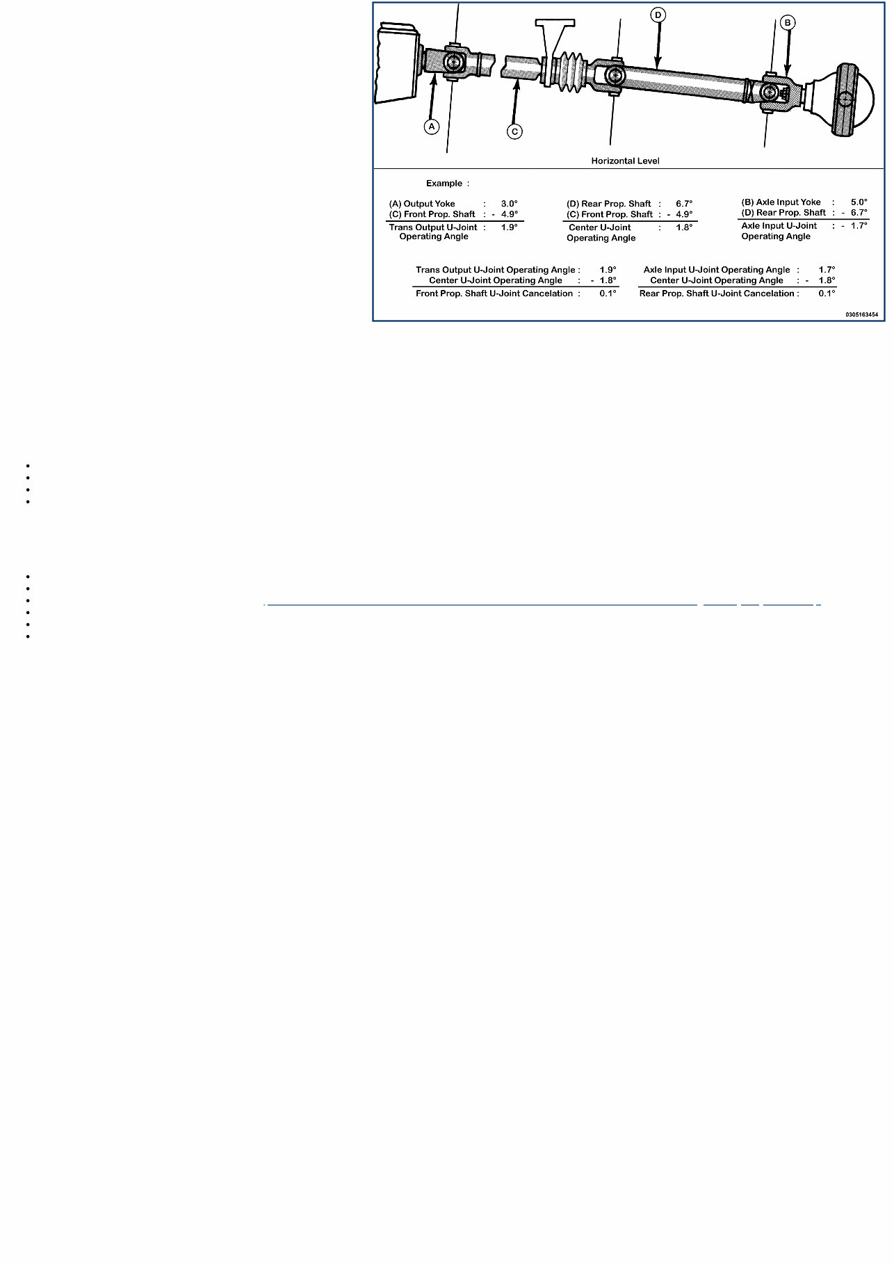
9. Place the inclinometer 7663 on the center universal joint bearing cap parallel to the shaft. Center the bubble in the sight glass and record the measurement (D). This measurement will give you the Rear Prop. Shaft Angle (D). 10. Place the inclinometer on the companion flange yoke bearing parallel to the shaft. Center the bubble in the sight glass and record the measurement. This measurement will give you the pinion Companion Flange Input Angle (B). 11. Place the inclinometer on the front driveshaft yoke bearing perpendicular to the shaft. Place the inclinometer at zero degrees and turn the shaft to center the bubble in the sight glass. 12. Rotate the inclinometer on the front driveshaft yoke bearing perpendicular to the shaft. Center the bubble in the sight glass and record the measurement. This measurement can also be taken at the rear end of the shaft. This measurement will give you the Front Prop. Shaft Angle (C). 13. Subtract (A) minus (C) to obtain the Transmission/Transfer Case Output Universal Joint Operating Angle. 14. Subtract (B) minus (C) to obtain the Center Universal Joint Operating Angle. 15. Subtract (B) minus (D) to obtain the Axle Input Universal Joint Operating Angle.
16. Subtract the Transmission/Transfer Case Output Universal Joint Operating Angle minus the Center Universal Joint Operating Angle to get the Front Propeller Shaft Universal Joint Cancelation. 17. Subtract the Axle Input Universal Joint Operating Angle minus the Center Universal Joint Operating Angle to get the Rear Prop. Shaft Universal Joint Cancelation. Refer to rules and example for additional information. RULES Good cancellation of U-joint operating angles should be within 1 degree. Keep operating angles less than 10 degrees for double cardan U-joint. Operating angles should be less than 3 degrees. Maintain at least 1/2 of one degree continuous operating propeller shaft angle. CHECKS IF MEASUREMENT OUTSIDE OF DESIRED OPERATING ANGLES Check condition of engine and transmission mounts. Check center support bearing for damage or excess wear. Check center support bearing adjustment (Refer to 03 - Differential and Driveline/Driveshaft/BEARING, Driveshaft Center, Light Duty/Adjustments) . Check for proper vehicle ride height. Check condition of any hardware and bushings at axle the measurement is outside of desired operating angle. Inspect for collision damage that may account for the measurement outside of desired operating angle.
03 - Differential and Driveline / Driveshaft / Technical Specifications TORQUE SPECIFICATIONS - DRIVESHAFT DESCRIPTION N·m Ft. Lbs. In. Lbs. COMMENT Front Driveshaft to Front Axle Bolts 115 85 — Do not reuse these fasteners. If removed, NEW fasteners must be installed and tightened to specifications. Rear Driveshaft Center Bearing Yoke Nut 149 110 — Rear Driveshaft Center Support Bearing Bolts 55 41 — Rear Driveshaft to Rear Axle Bolts M10 75 55 — Do not reuse these fasteners. If Removed, a NEW fastener must be installed and tightened to specifications. Rear Driveshaft to Rear Axle Bolts M12 115 85 — Do not reuse these fasteners. If removed, NEW fasteners must be installed and tightened to specifications. Rear Driveshaft to Transfer Case 75 55 — Do not reuse these fasteners. If removed, NEW fasteners must be installed and tightened to specifications.
03 - Differential and Driveline / Driveshaft / Special Tools SPECIAL TOOLS 1130 - Splitter, Bearing/Gear Originally Shipped In Kit Number(s) 6745, 6947, 6949, 9202, 9202A-CAN, 9202CC, 9299. 6052A - Installer, Bearing/Seal Originally Shipped In Kit Number(s) 6303, 6672, 8853. 6448A - Installer, Bearing/Gear Originally Shipped In Kit Number(s) 6947, 8667, 8837, 8867. 7663 - Inclinometer Originally Shipped In Kit Number(s) 7663-MC, XJ594. 938 - Bridge Originally Shipped In Kit Number(s) 6745, 6947, 6949, 9202, 9202A-CAN, 9202CC, 9299.
03 - Differential and Driveline / Driveshaft / BEARING, Driveshaft Center, Light Duty / Adjustments CENTER SUPPORT BEARING ADJUSTMENTS Launch shudder is a vibration that occurs at first acceleration from a stop. Shudder vibration usually peaks at the engines highest torque output. Shudder is a symptom associated with vehicles using a two-piece driveshaft. To decrease shudder, lower the center support bearing in 3.0 mm (0.125 in.) increments. Use shim stock or fabricated plates. Do not use washers. Replace the original bolts with the appropriate length bolts.
1 - Alignment Reference Mark (Center Yoke) 2 - Alignment Reference Mark (Front Shaft) 1 - Center Yoke 2 - Nut 3 - Washer 1 - Bearing 2 - Bearing Splitter 3 - Bridge 03 - Differential and Driveline / Driveshaft / BEARING, Driveshaft Center, Light Duty / Removal and Installation REMOVAL AND INSTALLATION Special Tools: Click to display a list of tools used in this procedure REMOVAL 1. Remove the rear driveshaft. 2. Make installation reference marks on rear shaft, center bearing yoke and front shaft. 3. Remove joint from center bearing yoke. 4. Remove center bearing yoke nut and washer. Discard yoke nut. 5. Remove center bearing yoke from shaft with two jaw puller. 6. Position Bearing Splitter Tool 1130 between propeller shaft and center bearing. 7. Install Bridge 938 on the splitter and remove center bearing. INSTALLATION
1 - Center Bearing 2 - Boot Collar 1 - Bearing 2 - Boot Collar 3 - Bearing/Seal Installer 1 - Alignment Reference Mark (Center Yoke) 2 - Alignment Reference Mark (Front Shaft) 1. Install a NEW collar on the shaft if it is removed and drive it into position with the appropriate tool. 2. Install a NEW bearing (1) on the shaft using the Installer, Bearing/Seal 6052A (3). 3. Clean the shaft splines and apply a light coat of Mopar™ multi-purpose grease to the splines. 4. Install center bearing yoke to the driveshaft with reference marks aligned. 5. Install NEW nut and washer and tighten nut to the proper (Torque Specifications) . 6. Install joint in center bearing yoke. 7. Install the driveshaft in the vehicle (Refer to 03 - Differential and Driveline/Driveshaft/SHAFT, Drive/Removal and Installation) .
1 – Stabilizer Bar Bushing Bolts 2 – Stabilizer Bar 1 – Driveshaft To Front Axle Bolts 2 – Front Driveshaft 1 - Front Output Shaft Splines 2 - Front Output Shaft Oil Seal Slinger 3 - Front Output Shaft O-Ring 03 - Differential and Driveline / Driveshaft / SHAFT, Drive, Front Light Duty / Removal and Installation FRONT DRIVESHAFT REMOVAL 1. Raise and support the vehicle (Refer to 04 - Vehicle Quick Reference/Hoisting/Standard Procedure) . 2. If equipped, remove the skid plate (Refer to 13 - Frame and Bumpers/Under Body Protection/PLATE, Skid/Removal and Installation) . 3. Remove the stabilizer bar bushing bolts and let the stabilizer bar hang. 4. Mark a line across the axle companion flange, driveshaft, flange yoke and transfer case for installation reference. 5. Remove and DISCARD the front driveshaft to front axle bolts. 6. Remove the front driveshaft. INSPECTION: Clean and inspect the front output shaft splines. Inspect the front output shaft O-ring, replace if damaged. INSTALLATION Follow the removal procedure in reverse for general reassembly of the components on the vehicle. The steps listed below are calling out specific procedures that should be followed during installation. Install the front driveshaft with all the reference marks aligned. Install NEW front driveshaft to front axle bolts and tighten to the proper (Torque Specifications). Tighten the stabilizer bar bushing bolts to the proper (Torque Specifications) . If equipped, tighten the skid plate bolts to the proper (Torque Specifications) .
If You'Re A Diy Enthusiast, This 2020 RAM 1500 Pickup Service & Repair Manual Is A Must-Have For Fixing Any Problems On Your Vehicle. With Step-By-Step Instructions, Clear Images, And Exploded-View Illustrations Provided By The Manufacturer, You'Ll Have All The Information You Need To Troubleshoot And Replace Any Parts That May Need Maintenance.
While Your Vehicle Is Undoubtedly Durable, Regular Maintenance Is Still Necessary. And Even With Proper Upkeep, Certain Parts Will Eventually Wear Out And Need To Be Replaced. Thankfully, This Repair Manual Has You Covered With The Manufacturer'S Recommended Troubleshooting Charts And Replacement Procedures.
No More Flipping Through Hundreds Of Pages To Find What You Need. No More Dealing With Greasy, Torn, Or Lost Pages. With This Electronic Manual, You Can Easily Search, Screenshot, Or Bookmark Important Information For Quick Access. And If You Prefer A Physical Copy, Simply Print It Out.
This Manual Is Printable And Available In English For Compatibility With Any Electronic Device, Including Pc And Mac Computers, Android And Apple Smartphones And Tablets, And More. All You Need Is Adobe Reader (Free) To Access It. So Why Not Save On Repairs, Increase Your Vehicle'S Reliability, And Keep The Repair Shop At Bay With This Comprehensive Repair Manual?
Recently Viewed
5,521,897Happy Clients
2,594,462eManuals
1,120,453Trusted Sellers
15Years in Business
Price:
Actual Price:
2020 RAM 1500 Pickup 3.0L V6 Turbo Diesel Gen 3 Service & Repair Manual