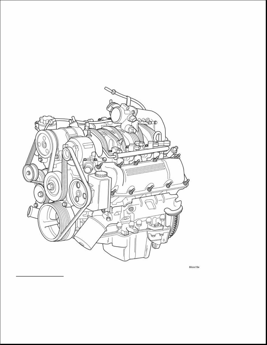
ENGINE 3.7L - Service Information - Ram 1500 Pickup DESCRIPTION DESCRIPTION Fig. 1: 3.7L ENGINE Courtesy of CHRYSLER LLC The 3.7 liter (226 CID) six-cylinder engine is an 90° single overhead camshaft engine. The cast iron cylinder block is made up of two different components; the first component is the cylinder bore and upper block, the second component is the bedplate that comprises the lower portion of the cylinder block and houses the lower half of the crankshaft main bearings. The cylinders are numbered from front to rear with the left bank being numbered 1, 3 and 5 and the right bank being numbered 2, 4 and 6. The firing order is 1-6-5-4-3-2. The engine
serial number is located at the right front side of the engine block. DIAGNOSIS AND TESTING INTRODUCTION Engine diagnosis is helpful in determining the causes of malfunctions not detected and remedied by routine maintenance. These malfunctions may be classified as either performance (e.g., engine idles rough and stalls) or mechanical (e.g., a strange noise). Refer to ENGINE DIAGNOSIS - PERFORMANCE and MECHANICAL for possible causes and corrections of malfunctions. Additional tests and diagnostic procedures may be necessary for specific engine malfunctions that can not be isolated with the Service Diagnosis charts. Information concerning additional tests and diagnosis is provided within the following diagnosis: Cylinder Compression Pressure Test. Refer to CYLINDER COMPRESSION PRESSURE LEAKAGE Cylinder Combustion Pressure Leakage Test: Refer to CYLINDER COMBUSTION PRESSURE LEAKAGE . Engine Cylinder Head Gasket Failure Diagnosis: Refer to CYLINDER HEAD GASKET . Intake Manifold Leakage Diagnosis: Refer to INTAKE MANIFOLD LEAKS . ENGINE DIAGNOSIS - PERFORMANCE CONDITION POSSIBLE CAUSE CORRECTION ENGINE WILL NOT START 1. Weak battery 1. Charge or replace as necessary. 2. Corroded or loose battery connections. 2. Clean and tighten battery connections. Apply a coat of light mineral grease to the terminals. 3. Faulty starter. 3. Refer to Electrical - Engine Systems/Starting - Diagnosis and Testing . 4. Faulty coil or control unit. 4. Refer to Electrical - Ignition Control/Ignition Control/COIL, Ignition - Removal . 5. Incorrect spark plug gap. 5. Correct as necessary. 6. Incorrect right bank cam timing. 6. Refer to TIMING VERIFICATION . 7. Dirt or water in fuel system. 7. Clean system and replace fuel filter. 8. Faulty fuel pump, relay or wiring. 8. Repair or replace as necessary. 9. Faulty cam or crank sensor 9. Refer to Ignition system.
MECHANICAL ENGINE STALLS OR ROUGH IDLE 1. Vacuum leak. 1. Inspect intake manifold and vacuum hoses, repair or replace as necessary. 2. Faulty crank position sensor 2. Replace crank position sensor. 3. Faulty coil. 3. Refer to Electrical - Ignition Control/Ignition Control/COIL, Ignition - Removal . 4. Incorrect cam timing. 4. See Engine/Valve Timing - Standard Procedure . ENGINE LOSS OF POWER 1. Dirty or incorrectly gapped spark plugs. 1. Correct as necessary. 2. Dirt or water in fuel system. 2. Clean system and replace fuel filter. 3. Faulty fuel pump. 3. Refer to Fuel System/Fuel Delivery - Specifications . 4. Blown cylinder head gasket. 4. Replace cylinder head gasket. 5. Low compression. 5. See CYLINDER COMPRESSION PRESSURE LEAKAGE , repair as necessary. 6. Burned, warped or pitted valves. 6. Replace as necessary. 7. Plugged or restricted exhaust system. 7. Inspect and replace as necessary. 8. Faulty coil. 8. Refer to Electrical - Ignition Control/Ignition Control/COIL, Ignition - Removal . 9. Incorrect cam timing. 9. Refer to TIMING VERIFICATION . ENGINE MISSES ON ACCELERATION 1. Spark plugs dirty or incorrectly gapped. 1. Correct as necessary. 2. Dirt in fuel system. 2. Clean fuel system. 3. Burned, warped or pitted valves. 3. Replace as necessary. 4. Faulty coil. 4. Refer to Electrical - Ignition Control/Ignition Control/COIL, Ignition - Removal . ENGINE MISSES AT HIGH SPEED 1. Spark plugs dirty or incorrectly gapped. 1. Correct as necessary. 2. Faulty coil. 2. Refer to Electrical - Ignition Control/Ignition Control/COIL, Ignition - Removal . 3. Dirt or water in fuel system. 3. Clean system and replace fuel filter. CONDITION POSSIBLE CAUSES CORRECTIONS NOISY VALVES 1. High or low oil level in crankcase. 1. Refer to Vehicle Quick Reference/Capacities and Recommended Fluids -
LUBRICATION Specifications . 2. Thin or diluted oil. 2. Change oil and filter. 3. Low oil pressure. 3. Check oil pump, if OK, check rod and main bearings for excessive wear. 4. Dirt in lash adjusters. 4. Replace as necessary. 5. Worn rocker arms. 5. Replace as necessary. 6. Worn lash adjusters 6. Replace as necessary. 7. Worn valve guides. 7. Inspect the valve guides for wear, cracks or looseness. If either condition exists, replace the cylinder head. See Engine/Cylinder Head - Removal (left). See Engine/Cylinder Head - Removal (right). 8. Excessive runout of valve seats on valve faces. 8. See Engine/Cylinder Head/VALVES, Intake and Exhaust - Standard Procedure . CONNECTING ROD NOISE 1. Insufficient oil supply. 1. Refer to Vehicle Quick Reference/Capacities and Recommended Fluids - Specifications . 2. Low oil pressure. 2. Check oil pump, if OK, check rod and main bearings for excessive wear. 3. Thin or diluted oil. 3. Change oil and filter. 4. Excessive bearing clearance. 4. Replace as necessary. 5. Connecting rod journal out-of- round. 5. Service or replace crankshaft. 6. Misaligned connecting rods. 6. Replace bent connecting rods. MAIN BEARING NOISE 1. Insufficient oil supply. 1. Refer to Vehicle Quick Reference/Capacities and Recommended Fluids - Specifications . 2. Low oil pressure. 2. Check oil pump, if OK, check rod and main bearings for excessive wear. 3. Thin or diluted oil. 3. Change oil and filter. 4. Excessive bearing clearance. 4. Replace as necessary. 5. Excessive end play. 5. Check thrust washers for wear. 6. Crankshaft journal out-of round. 6. Service or replace crankshaft. 7. Loose flywheel or torque converter. 7. Tighten to correct torque
CONDITION POSSIBLE CAUSES CORRECTION OIL LEAKS 1. Gaskets and O-Rings. Misaligned or damaged. 1. Replace as necessary. - - 2. Loose fasteners, broken or porous metal parts. 2. Tighten fasteners, repair or replace metal parts. 3. Crankshaft rear seal 3. Replace as necessary. See Engine/Engine Block/SEAL, Crankshaft Oil - Removal . 4. Crankshaft seal flange. Scratched, nicked or grooved. 4. Polish or replace crankshaft. 5. Oil pan flange cracked. 5. Replace oil pan. See Engine/Lubrication/PAN, Oil - Removal . 6. Timing chain cover seal, damaged or misaligned. 6. Replace seal. See Engine/Engine Block/SEAL, Crankshaft Oil - Removal . 7. Scratched or damaged vibration damper hub. 7. Polish or replace damper. See Engine/Engine Block/DAMPER, Vibration - Removal . OIL PRESSURE DROP 1. Low oil level. 1. Check and correct oil level. See Engine/Lubrication/OIL - Standard Procedure . 2. Faulty oil pressure sending unit. 2. Replace sending unit. See Engine/Lubrication/SWITCH, Oil Pressure - Removal . 3. Low oil pressure. 3. Check oil pump and bearing clearance. See Engine/Lubrication/PUMP, Engine Oil - Inspection . 4. Clogged oil filter. 4. Replace oil filter. See Engine/Lubrication/FILTER, Engine Oil - Removal . 5. Worn oil pump. 5. Replace oil pump. See Engine/Lubrication/PUMP, Engine Oil - Removal . 6. Thin or diluted oil. 6. Change oil and filter. See Engine/Lubrication/FILTER, Engine Oil - Removal . 7. Excessive bearing clearance. 7. Replace as necessary. See Engine/Engine Block/ROD, Piston and Connecting - Standard Procedure . 8. Oil pump relief valve stuck. 8. Replace oil pump. See Engine/Lubrication/PUMP, Engine Oil - Removal . 9. Oil pick up tube loose, damaged or clogged. 9. Replace as necessary. See Engine/Lubrication/PAN, Oil - Removal . OIL PUMPING AT RINGS; SPARK PLUGS FOULING 1. Worn or damaged rings. 1. Hone cylinder bores and replace rings. See Engine/Engine Block/RING(S), Piston -
CYLINDER COMPRESSION PRESSURE LEAKAGE 1. Clean the spark plug recesses with compressed air. 2. Remove the spark plugs and record the cylinder number of each spark plug for future reference. 3. Inspect the spark plug electrodes for abnormal firing indicators such as fouled, hot, oily, etc. 4. Disable the fuel system and perform the fuel system pressure release procedure. Refer to Fuel System/Fuel Delivery - Standard Procedure . 5. Insert a compression pressure gauge and rotate the engine with the engine starter motor for three revolutions. 6. Record the compression pressure on the 3rd revolution. Continue the test for the remaining cylinders. Standard Procedure . 2. Carbon in oil ring slots. 2. Replace rings. See Engine/Engine Block/RING(S), Piston - Standard Procedure . 3. Incorrect ring size installed. 3. Replace rings. See Engine/Engine Block/RING(S), Piston - Standard Procedure . 4. Worn valve guides. 4. Inspect the valve guides for wear, cracks or looseness. If either condition exist, replace the cylinder head. See Engine/Cylinder Head - Removal (left). See Engine/Cylinder Head - Removal (right). 5. Leaking valve guide seals. 5. Replace valve guide seals. See Engine/Cylinder Head/VALVES, Intake and Exhaust - Removal for left cylinder head. NOTE: Refer to left cylinder head information for right cylinder head procedure. NOTE: The results of a cylinder compression pressure test can be utilized to diagnose several engine malfunctions. NOTE: Ensure the battery is completely charged and the engine starter motor is in good operating condition. Otherwise the indicated compression pressures may not be valid for diagnosis purposes. NOTE: The recommended compression pressures are to be used only as a guide to diagnosing engine problems. An engine should not be disassembled to determine the cause of low compression unless some malfunction is present.
7. Compression should not be less than 689 kPa (100 psi) and not vary more than 25 percent from cylinder to cylinder. 8. If one or more cylinders have abnormally low compression pressures, repeat the compression test. 9. If one or more cylinders continue to have abnormally low compression pressures, perform the cylinder combustion pressure leakage test. See CYLINDER COMBUSTION PRESSURE LEAKAGE . CYLINDER COMBUSTION PRESSURE LEAKAGE The combustion pressure leakage test provides an accurate means for determining engine condition. Combustion pressure leakage testing will detect: Exhaust and intake valve leaks (improper seating). Leaks between adjacent cylinders or into water jacket. Any causes for combustion/compression pressure loss. 1. Check the coolant level and fill as required. DO NOT install the radiator cap. 2. Start and operate the engine until it attains normal operating temperature, then turn the engine OFF. 3. Remove the spark plugs. 4. Remove the oil filler cap. 5. Remove the air cleaner hose. 6. Calibrate the tester according to the manufacturer's instructions. The shop air source for testing should maintain 483 kPa (70 psi) minimum, 1,379 kPa (200 psi) maximum and 552 kPa (80 psi) recommended. 7. Perform the test procedures on each cylinder according to the tester manufacturer's instructions. Set piston of cylinder to be tested at TDC compression. While testing, listen for pressurized air escaping through the throttle body, tailpipe and oil filler cap opening. Check for bubbles in the radiator coolant. All gauge pressure indications should be equal, with no more than 25% leakage. FOR EXAMPLE: At 552 kPa (80 psi) input pressure, a minimum of 414 kPa (60 psi) should be maintained in the cylinder. Refer to CYLINDER COMBUSTION PRESSURE LEAKAGE DIAGNOSIS CHART . CYLINDER COMBUSTION PRESSURE LEAKAGE DIAGNOSIS CHART NOTE: If the same cylinder or cylinders repeat an abnormally low reading on the second compression test, it could indicate the existence of a problem in the cylinder in question. CONDITION POSSIBLE CAUSE CORRECTION AIR ESCAPES THROUGH THROTTLE BODY Intake valve bent, burnt, or not seated properly Inspect valve and valve seat. Reface or replace, as necessary. Inspect valve springs. Replace as
STANDARD PROCEDURE REPAIR DAMAGED OR WORN THREADS Damaged or worn threads can be repaired. Essentially, this repair consists of: Drilling out worn or damaged threads. Tapping the hole with a special Heli-coil Tap, or equivalent. Installing an insert into the tapped hole to bring the hole back to its original thread size. FORM-IN-PLACE GASKETS AND SEALERS There are numerous places where form-in-place gaskets are used on the engine. Care must be taken when applying form-in-place gaskets to assure obtaining the desired results.Do not use form-in-place gasket material unless specified. Bead size, continuity, and location are of great importance. Too thin a bead can result in leakage while too much can result in spill-over which can break off and obstruct fluid feed lines. A continuous bead of the proper width is essential to obtain a leak-free gasket. There are numerous types of form-in-place gasket materials that are used in the engine area. Mopar® Engine RTV GEN II, Mopar® ATF-RTV, and Mopar® Gasket Maker gasket materials, each have different properties and can not be used in place of the other. MOPAR® ENGINE RTV GEN II Mopar® Engine RTV GEN II is used to seal components exposed to engine oil. This material is a specially designed black silicone rubber RTV that retains adhesion and sealing properties when exposed to engine oil. necessary. AIR ESCAPES THROUGH TAILPIPE Exhaust valve bent, burnt, or not seated properly Inspect valve and valve seat. Reface or replace, as necessary. Inspect valve springs. Replace as necessary. AIR ESCAPES THROUGH RADIATOR Head gasket leaking or cracked cylinder head or block Remove cylinder head and inspect. Replace defective part MORE THAN 50% LEAKAGE FROM ADJACENT CYLINDERS Head gasket leaking or crack in cylinder head or block between adjacent cylinders Remove cylinder head and inspect. Replace gasket, head, or block as necessary MORE THAN 25% LEAKAGE AND AIR ESCAPES THROUGH OIL FILLER CAP OPENING ONLY Stuck or broken piston rings; cracked piston; worn rings and/or cylinder wall Inspect for broken rings or piston. Measure ring gap and cylinder diameter, taper and out-of-round. Replace defective part as necessary CAUTION: Be sure that the tapped holes maintain the original center line.
Moisture in the air causes the material to cure. This material is available in three ounce tubes and has a shelf life of one year. After one year this material will not properly cure. Always inspect the package for the expiration date before use. MOPAR® ATF RTV Mopar® ATF RTV is a specifically designed black silicone rubber RTV that retains adhesion and sealing properties to seal components exposed to automatic transmission fluid, engine coolants, and moisture. This material is available in three ounce tubes and has a shelf life of one year. After one year this material will not properly cure. Always inspect the package for the expiration date before use. MOPAR® GASKET MAKER Mopar® Gasket Maker is an anaerobic type gasket material. The material cures in the absence of air when squeezed between two metallic surfaces. It will not cure if left in the uncovered tube. The anaerobic material is for use between two machined surfaces. Do not use on flexible metal flanges. MOPAR® GASKET SEALANT Mopar® Gasket Sealant is a slow drying, permanently soft sealer. This material is recommended for sealing threaded fittings and gaskets against leakage of oil and coolant. Can be used on threaded and machined parts under all temperatures. This material is used on engines with multi-layer steel (MLS) cylinder head gaskets. This material also will prevent corrosion. Mopar® Gasket Sealant is available in a 13 oz. aerosol can or 4oz./16 oz. can w/applicator. FORM-IN-PLACE GASKET AND SEALER APPLICATION Assembling parts using a form-in-place gasket requires care but it's easier than using precut gaskets. Mopar® Gasket Maker material should be applied sparingly 1 mm (0.040 in.) diameter or less of sealant to one gasket surface. Be certain the material surrounds each mounting hole. Excess material can easily be wiped off. Components should be torqued in place within 15 minutes. The use of a locating dowel is recommended during assembly to prevent smearing material off the location. Mopar® Engine RTV GEN II or ATF RTV gasket material should be applied in a continuous bead approximately 3 mm (0.120 in.) in diameter. All mounting holes must be circled. For corner sealing, a 3.17 or 6.35 mm (1/8 or 1/4 in.) drop is placed in the center of the gasket contact area. Uncured sealant may be removed with a shop towel. Components should be torqued in place while the sealant is still wet to the touch (within 10 minutes). The usage of a locating dowel is recommended during assembly to prevent smearing material off the location. Mopar® Gasket Sealant in an aerosol can should be applied using a thin, even coat sprayed completely over both surfaces to be joined, and both sides of a gasket. Then proceed with assembly. Material in a can w/applicator can be brushed on evenly over the sealing surfaces. Material in an aerosol can should be used on engines with multi-layer steel gaskets. ENGINE GASKET SURFACE PREPARATION
You're Reading a Preview
What's Included?
Lifetime Access
Fast Download Speeds
Online & Offline Access
Access PDF Contents & Bookmarks
Full Search Facility
Print one or all pages of your manual
$37.99
2016 Dodge Ram 1500/2500/3500 OEM Service & Repair Manual
Get the comprehensive 2016 Dodge RAM 1500/2500/3500 Service & Repair Manual to tackle any maintenance or repair task for your truck. This manual covers a range of engines including 3.7L (1500), 4.7L (1500), 5.7L (1500 & 2500), 5.9L (2500 & 3500), and 6.7L (2500 & 3500).
Whether you're a professional mechanic or a DIY enthusiast, this manual equips you with the manufacturer's recommended troubleshooting charts and replacement procedures. It includes step-by-step instructions, clear images, and exploded-view illustrations to guide you through the process.
Regular maintenance is essential for the durability of your truck. With this manual, you can save on repairs, increase your vehicle's reliability, and minimize trips to the repair shop. No need to flip through numerous pages or worry about greasy, torn, or lost pages. This digital manual allows easy access, search, screenshot, and bookmark functions, making it more convenient than a traditional bound manual.
It is printable and compatible with various electronic devices including PC, Mac computers, Android and Apple smartphones, and tablets. All you need is Adobe Reader, which is available for free.
Reviews
Q&A
Recently Viewed
5,521,897Happy Clients
2,594,462eManuals
1,120,453Trusted Sellers
15Years in Business
Price:
Actual Price:
2016 Dodge Ram 1500/2500/3500 OEM Service & Repair Manual