

Dodge 46RE Transmission Service Workshop Shop Repair Manual
What's Included?
Fast Download Speeds
Online & Offline Access
Access PDF Contents & Bookmarks
Full Search Facility
Print one or all pages of your manual

INTRODUCTION
46RE, 47RE, 48RE,
No part of any ATSG publication may be reproduced, stored in any retrieval system or transmitted in any form or
by any means, including but not limited to electronic, mechanical, photocopying, recording or otherwise,
without written permission of Automatic Transmission Service Group. This includes all text illustrations,
tables and charts.
The information and part numbers contained in this booklet have
been carefully compiled from industry sources known for their
reliability, but ATSG does not guarantee its accuracy.
Copyright © ATSG 2011
1st Printing
April, 2011
AUTOMATIC TRANSMISSION SERVICE GROUP
18635 S.W. 107 AVENUE
CUTLER BAY, FLORIDA 33157
(305) 670-4161
1
DALE ENGLAND
FIELD SERVICE CONSULTANT
ED KRUSE
TECHNICAL CONSULTANT
WAYNE COLONNA
PRESIDENT
PETER LUBAN
TECHNICAL CONSULTANT
JIM DIAL
TECHNICAL CONSULTANT
GREGORY LIPNICK
TECHNICAL CONSULTANT
JON GLATSTEIN
TECHNICAL CONSULTANT
DAVID CHALKER
TECHNICAL CONSULTANT
GREG CATANZARO
TECHNICAL CONSULTANT
GERALD CAMPBELL
TECHNICAL CONSULTANT
We wish to thank Chrysler® Group for the information that has made this booklet possible.
The 46RE, 47RE and 48RE family of transmissions by the Chrysler Group, are fitted behind a wide variety of
engine sizes, including diesel, and across various vehicle lines. They are also available in 2WD and 4WD
configurations. Beginning at the start of production for model year 2005, Dodge trucks equipped with the 5.9L
diesel and 48RE transmission were equipped with an electronically controlled Transmission Throttle Valve
Actuator (TTVA). This Actuator has replaced the previous Throttle Valve Cable and all associated linkage.
A push-in Transmission Range Sensor was implemented in model year 2002 to replace the screw-in Park/Neutral
switch.
The 46RE, 47RE and 48RE transmissions are all four speed fully automatic units with an electronic governor.
They are equipped with a lock-up clutch in the torque converter. First through third gear ranges are provided by the
clutches, bands, low-roller clutch, and planetary gearsets in the transmission. Fourth gear is provided by the
overdrive unit (rear section) that contains an overdrive clutch, OD/direct clutch, overrun roller clutch, and planetary
gearset.
These units contain a front (direct) clutch, rear (forward) clutch, and OD/direct clutch which serve as the input
driving components. They also contain a kickdown (front) band, low/reverse (rear) band, overrun clutch, and the
overdrive clutch which serve as the holding components.

INDEX
DODGE, JEEP
46RE, 47RE, 48RE
2
Copyright © ATSG 2011
AUTOMATIC TRANSMISSION SERVICE GROUP
18635 S.W. 107 AVENUE
CUTLER BAY, FLORIDA 33157
(305) 670-4161
3
5
6
6
7
10
14
17
18
19
20
26
28
33
34
36
40
42
57
63
69
73
79
85
98
115
122
124
125
125
130
134
142
144
GENERAL DESCRIPTION AND VEHICLE APPLICATION CHART ....................................
INTERNAL COMPONENT LOCATIONS ..................................................................................
COMPONENT APPLICATION CHART, ID TAG LOCATION ................................................
FLUID SPECIFICATIONS ..........................................................................................................
EXTERNAL ELECTRONIC COMPONENTS ............................................................................
TRANSMISSION THROTTLE VALVE ACTUATOR WIRE SCHEMATIC .............................
CONTROL MODULE LOCATIONS ............................................................................................
ELECTRICAL CONNECTOR AND TERMINAL IDENTIFICATION .....................................
TRANSMISSION CONTROL RELAY INFORMATION ............................................................
TOW/HAUL-OVERDRIVE CANCEL SWITCH .........................................................................
VEHICLE WIRE SCHEMATICS ................................................................................................
DIAGNOSTIC TROUBLE CODES ..............................................................................................
INTERNAL ELECTRONIC COMPONENTS .............................................................................
LINE PRESSURE SPECS AND PRESSURE TAP LOCATIONS ..............................................
ELECTRONIC GOVERNOR INFORMATION ..........................................................................
GOVERNOR SOLENOID AND SENSOR DIAGNOSIS ............................................................
CASE PASSAGE IDENTIFICATION .........................................................................................
TRANSMISSION DISASSEMBLY ..............................................................................................
COMPONENT REBUILD
TRANSMISSION CASE ASSEMBLY ..................................................................................
OIL PUMP ASSEMBLY ........................................................................................................
FRONT (DIRECT) CLUTCH HOUSING ASSEMBLY .......................................................
REAR (FORWARD) CLUTCH HOUSING ASSEMBLY .....................................................
TRANSMISSION GEARTRAIN ASSEMBLY ......................................................................
OVERDRIVE UNIT ASSEMBLY .........................................................................................
OVERDRIVE ROLLER CLUTCH FREEWHEEL DIRECTION .......................................
CHECK BALL LOCATIONS .................................................................................................
VALVE BODY ASSEMBLY ...................................................................................................
VALVE BODY ADJUSTMENTS ...........................................................................................
TRANSMISSION ASSEMBLY .....................................................................................................
LOW ROLLER CLUTCH FREEWHEEL DIRECTION ............................................................
BAND ADJUSTMENTS ...............................................................................................................
OVERDRIVE SELECTIVE MEASUREMENTS ........................................................................
THRUST WASHER AND THRUST BEARING LOCATIONS ..................................................
TORQUE SPECIFICATIONS ......................................................................................................
GENERAL DESCRIPTION
Figure 1
VEHICLE APPLICATION CHART
VEHICLE YEAR ENGINE COUNTRY TRANSMISSION
GRAND CHEROKEE
DODGE, DURANGO
DODGE, RAM PICK-UP
DODGE, RAM PICK-UP
DODGE, RAM PICK-UP
DODGE, RAM PICK-UP
DODGE, RAM PICK-UP
DODGE, VAN/WAGON
DODGE, DAKOTA
1998
1998-03
1995-02
1995-02
1995-02
2003-07
2003-07
1995-03
1998-00
4.7L (V8)
5.9L, (V8)
5.2L, 5.9L, (V8)
5.9L, (Diesel)
8.0L (V10)
5.9L (Diesel)
8.0L (V10)
5.9L, (V8)
5.2L (V8)
USA,
USA,
USA, MEX,
USA, MEX,
USA, MEX,
USA, MEX,
USA, MEX,
USA,
CAN, MEX,
46RE
46RE
46RE
47RE
47RE
48RE
48RE
46RE
46RE
3
Copyright © 2011 ATSG
AUTOMATIC TRANSMISSION SERVICE GROUP
Technical Service Information
The 46RE, 47RE and 48RE family of transmissions by
the Chrysler Group are fitted behind a wide variety of
engine sizes and across various vehicle lines, as shown
in Figure 1. They are also available in 2WD and 4WD
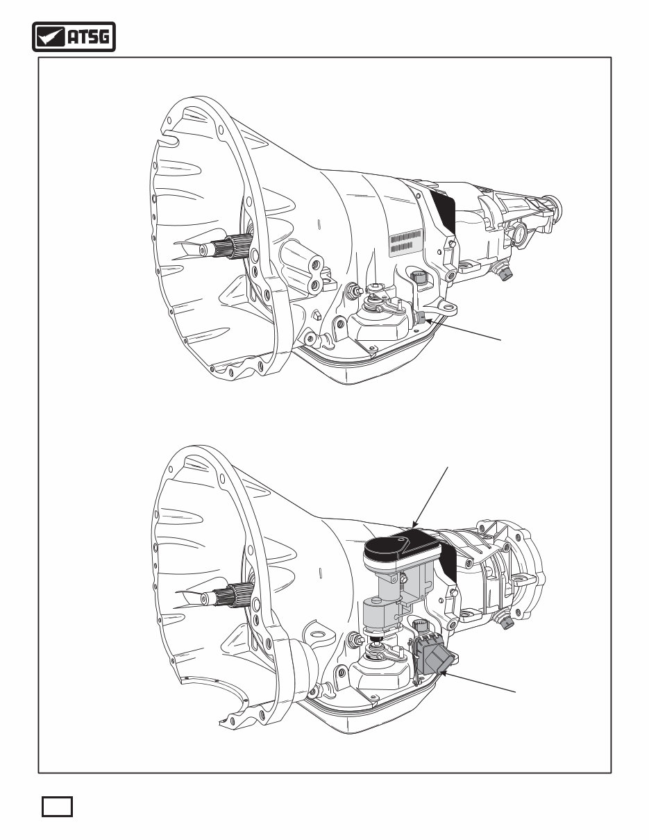
configurations, as shown in Figure 2. Notice also in
Figure 2, at the start of production for model year 2005,
Dodge trucks equipped with the 5.9L diesel and 48RE
transmission, were equipped with an electronically
controlled Transmission Throttle Valve Actuator
(TTVA). This Actuator has replaced the previous
Throttle Valve Cable and all associated linkage. The
push-in Range Sensor was implemented in model year
2002.
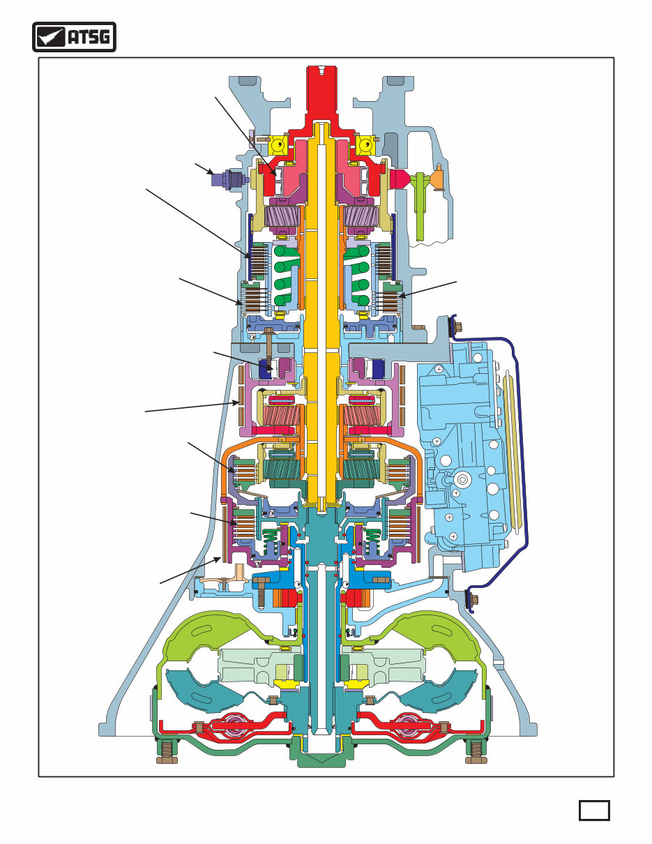
The 46RE, 47RE and 48RE transmissions are all four
speed fully automatic units with an electronic governor.
They are equipped with a lock-up clutch in the torque
converter. First through third gear ranges are provided
by the clutches, bands, low-roller clutch, and planetary
gearsets in the transmission. Fourth gear is provided by
the overdrive unit (rear section) that contains an
overdrive clutch, OD/direct clutch, overrun roller
clutch, and planetary gearset. Refer to Figure 3 for the
internal component locations and identification.
These units contain a front clutch, rear clutch, and
OD/direct clutch which serve as the input driving
components. They also contain a kickdown (front)
band, low/reverse (rear) band, overrun clutch, and the
overdrive clutch which all serve as the holding
components.
The driving and holding components combine to select
the necessary planetary gear components in the front,
rear, or overdrive planetary gearset and transfer the
engine power from the input shaft through to the output
shaft. Refer to Figure 4 for the component application
chart for which component is applied for each gear.
First, second and third gear shifts are controlled by an
electronic governor solenoid, that is mounted on the
valve body assembly. The shift into fourth gear and
torque converter clutch are controlled by individual
seperate solenoids that are also mounted on the valve
body assembly.
The valve body is mounted on the lower side of the
transmission and contains the valves necessary for
pressure regulation, fluid flow control and clutch or
band application. The valve body assembly has
received several upgrades and changes over the years.
The oil pump is mounted at the front of the
transmission and is driven by the torque converter hub.
The oil pump supplies the pressure necessary for clutch
and/or band application and transmission lubrication.
PK5 54 8AA 97 58 28 23 2 4 1 9
2
2
3
3
8
8
6
6
K 9 F1 9 TP TK 7 5 2 4 8
2 4 8 K 8 2 A P 5 5 3 A
3 28
AA
SIEMENS VDO
SIEMENS VDO
0
0
6
6
4
4
1
1
PK52 4238 A 297 589 85 A 41
K 94 8 TP TK 7 F1 9 2 5
2 P 5 5 3A K2 4 8 A 8
28 3
A A
Figure 2
4
Copyright © 2011 ATSG
AUTOMATIC TRANSMISSION SERVICE GROUP
Technical Service Information
2WD Gas
Version
4WD Diesel
Version
Some Models Equipped With
Screw-In P/N Switch
(1995-2001 Models)
Some Models Equipped With
Push-In Range Sensor
(2002-Up All Models)
Throttle Valve Acuator
(2005-Up Diesel Models Only)
5
AUTOMATIC TRANSMISSION SERVICE GROUP
Technical Service Information
Copyright © 2011 ATSG
Figure 3
INTERNAL COMPONENT LOCATION AND IDENTIFICATION
FRONT
(INTERMEDIATE)
BAND
REAR
(LOW/REVERSE)
BAND
LOW ROLLER
CLUTCH
FRONT
(DIRECT)
CLUTCH
REAR
(FORWARD)
CLUTCH
OVERDRIVE
CLUTCH
(Diesel)
OVERDRIVE
CLUTCH
(Gasoline)
OVERDRIVE
ROLLER
CLUTCH
OUTPUT
SPEED
SENSOR
OVERDRIVE/DIRECT
CLUTCH
PK5 4 29 15 285 238AA 74 89
2
2
3
3
8
8
6
6
K 9 F1 TK 7 59 TP 2 4 8
2 4 K 8 2 8A P 5 5 3 A
3 28
A A
COMPONENT APPLICATION CHART
Gear Ratio
2.20
2.45
2.45
1.45
1.45
1.00
0.69
Front
Clutch
Front
Band
Rear
Clutch
Rear
Band
Low-Roller
Clutch
Overdrive
Clutch
OD/Direct
Clutch
OD Roller
Clutch
Reverse
OD-1st
Man-1st
ON
ON
ON
ON
ON
ON
ON
ON
ON
ON
Hold
Hold
ON
ON
ON
ON Hold
Hold
Hold
Hold
Hold
ON
ON
ON
ON ON ON
OD-2nd
Man-2nd
OD-3rd
OD-4th
Note: The torque converter clutch may be applied in 3rd or 4th gears. The torque converter clutch may also be engaged in Manual 2nd
gear position, if high transmission temperatures are detected by the TCM/PCM/ECM.
Figure 4
Figure 4A
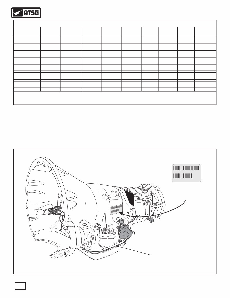
Bar Code Label
Located Here
ID Numbers Also Etched Into
Case Pan Rail Here
IDENTIFICATION TAG LOCATION
IDENTIFICATION TAG AND FLUID REQUIREMENTS
Fluid Requirements
"ATF+4"
Copyright © 2011 ATSG
TPKTK2974F1589
PK52854238AA
238
AA
The Bar Code Label is located on the left hand side of
the transmission case, as shown in Figure 4A.
Transmission identification numbers are also etched
into the left side of case pan rail just above the oil pan
gasket, as shown in Figure 4A. Always refer to this
information when ordering replacement parts.
These units require "ATF+4" fluid, as shown in Figure
4A.
6
Copyright © 2011 ATSG
AUTOMATIC TRANSMISSION SERVICE GROUP
Technical Service Information
PK52854238AA 2974 1589
Part
Number
Build
Date
Serial
Number
{
{
{
7
Copyright © 2011 ATSG
AUTOMATIC TRANSMISSION SERVICE GROUP
Technical Service Information
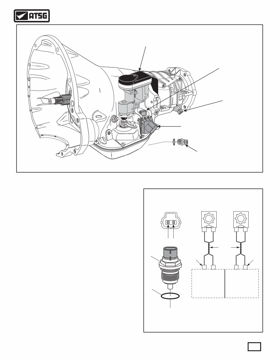
EXTERNAL ELECTRONIC COMPONENTS
Output Speed Sensor (OSS)
PK5 54 8AA 97 58 28 23 2 4 1 9
2
2
3
3
8
8
6
6
K 9 F1 9 TP TK2 7 58 4
2 4 8 K 8 2 A P 5 5 3 A
3 28
AA
SIEMENS VDO
SIEMENS VDO
Throttle Valve Actuator
2005-Up Diesel Only
Output Speed
Sensor All Models
8-Way Case
Connector All Models
"Push-In" Range
Sensor 2002-Up
"Screw-In" Park/Neutral
Switch 1995-2001
EXTERNAL ELECTRONIC COMPONENT LOCATIONS
The Output Speed Sensor (OSS) is located in the
overdrive case housing, as shown in Figure 5, and is
positioned over the park gear. The OSS monitors
rotating speed of the output shaft.
The OSS is triggered by the external park lugs on the
rear planetary ring gear to determine the exact
transmission output shaft speed. The OSS signal, and
other inputs, are used by the TCM/PCM/ECM to
determine the required governor pressure for current
conditions. This has a direct effect on which gear is
chosen for the vehicle. The controller also uses this
information to schedule torque converter lock-up.
Should the OSS fail, the speed signal from the ABS
control module is used as a back-up, and code P0720
will be stored in TCM/PCM/ECM memory.
The OSS sensor and wire schematic for Gas and Diesel
is shown in Figure 6.
Figure 5
OUTPUT SPEED SENSOR (OSS)
Special Note:
The OSS is best checked using a scope under
operating conditions.
1
28
2
25
1
44
2
45
Twisted
Pair
C2
Conn
C2
Conn
OSS SIG
OSS GND
OSS GND
OSS SIG
ECM 2004-UP
(DIESEL)
PCM 1996-03
(GAS & DIESEL)
1 2
Output Speed Sensor
Harness Connector
(Face View)
13
14
Figure 6
13 OUTPUT SHAFT SPEED SENSOR (ALL MODELS).
14 OUTPUT SPEED SENSOR "O" RING SEAL.
Copyright © 2011 ATSG
8
AUTOMATIC TRANSMISSION SERVICE GROUP
Technical Service Information
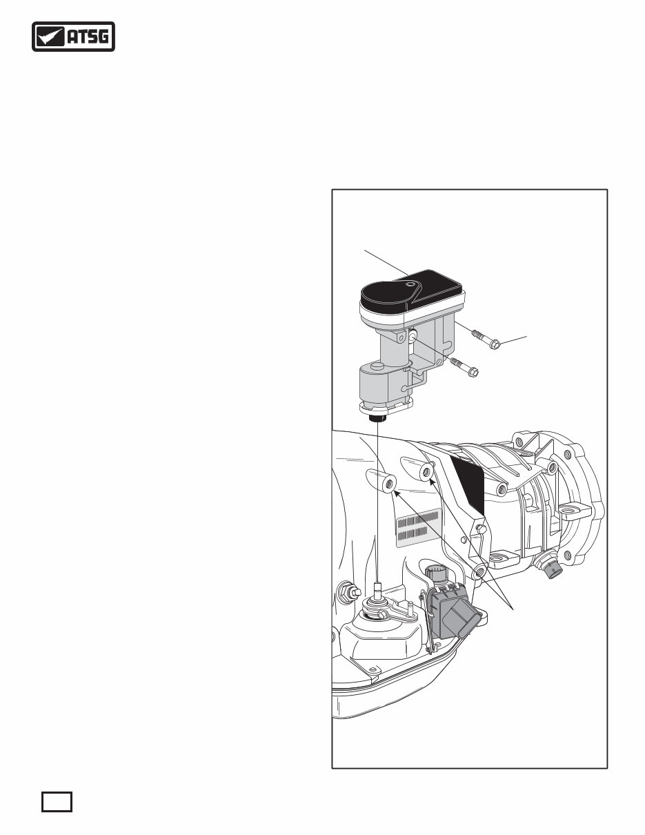
6 THROTTLE VALVE ACTUATOR (2005-UP DIESEL ONLY).
7 THROTTLE VALVE ACTUATOR BOLTS (2 REQUIRED).
6
7
EXTERNAL ELECTRONIC COMPONENTS (CONT'D)
Transmission Throttle Valve Acuator (TTVA)
Figure 7
Beginning at the start of production for the 2005 model
year, all Dodge trucks equipped with the 5.9L diesel
engine and the 48RE transmission, received an
electronically controlled Transmission Throttle Valve
Actuator (TTVA), as shown in Figure 7, for improved
shift control. The TTVA is mechanically connected to
the throttle valve in the valve body by the "D" shaped
opening in the bottom of the TTVA shaft and retained
with two mounting bolts, as shown in Figure 7. This
required two added bosses to the transmission case.
The TTVA has replaced the previous Throttle Valve
Cable and all associated mechanical linkage, on diesel
models only.
The TTVA consists of an electronic DC motor, two
potentiometers and a gear driven system that controls
all functions of the throttle valve in the valve body. The
position of the geartrain is monitored by the TTVA
Position sensor which supplies an input to the Engine
Control Module (ECM).
The TTVA is controlled by the ECM thru the inputs of
Accelerator Position Sensor 1 and 2. Refer to the charts
in Figure 8 for observed voltage and percent of opening,
from a working vehicle, of APP1 and APP2 to the
voltages that control the TTVA and the TTVA position
voltage feedback to the ECM. Refer to Figure 11 for
wiring schematic of the accelerator pedal position
sensor to assist you in the diagnosis process as
necessary.
Note: If the TTVA is removed or replaced, the ECM
will have to relearn it's "0" position. The ignition will
have to be turned on, with the engine off, for 30
seconds to accomplish "Auto Zero."
With the addition of the TTVA a new wiring harness was
required. Refer to Figure 10 for a partial wire schematic
of the TTVA and its connectors. Refer to Figure 9 for a
list of new Diagnostic Trouble Codes related to the
TTVA.
If a new case is required, it must be a 2005 or later case
because of the added bosses to the case to accommodate
the TTVA.
Added Case
Bosses
PK 85 238 A 29 4 89 52 4 A 7 15
K T K297 F1 9 P T 4 58
85 38A PK52 42 A
8 23
A A
SIEMENS VDO
SIEMENS VDO
Copyright © 2011 ATSG
9
AUTOMATIC TRANSMISSION SERVICE GROUP
Technical Service Information
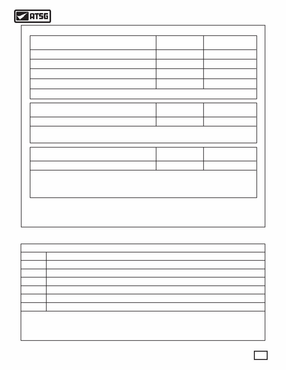
"OBSERVED" VOLTAGE AND PERCENTAGE CHARTS
TTVA Position Sensor (Voltage)
CLOSED
THROTTLE
TTVA POSITION SENSOR SIGNAL
WIDE OPEN
THROTTLE
3.78V .73V
Note: TTVA motor control and TTVA position sensor are subject to change, and there are no adjustments. The ECM will
re-calibrate its current "0" position when the ignition is turned on and the engine not running for 30 seconds.
TTVA + (Voltage)
CLOSED
THROTTLE
TTVA MOTOR VOLTAGE
WIDE OPEN
THROTTLE
2.0 -2.5V 0 -.70V
Note: Using a DVOM set to DC volts, backprobe terminal number 8 at the ECM C1 60-way connector with the red probe and
the black probe to a good ground (See Figure 10).
Note: On 2005 diesel models only, using a DVOM set to DC volts, backprobe terminal number 35 at the ECM C1 60-way
connector with the red probe and the black probe to a good ground (See Figure 10).
Note: On 2006-Up diesel models only, using a DVOM set to DC volts, backprobe terminal number 27 at the ECM C2 50-way
connector with the red probe and the black probe to a good ground (See Figure 10).
Accelerator Pedal Position Sensor 1 (Percent)
Accelerator Pedal Position Sensor 2 (Percent)
Accelerator Pedal Position Sensor 1 (Voltage)
Accelerator Pedal Position Sensor 2 (Voltage)
CLOSED
THROTTLE
WIDE OPEN
THROTTLE
2 %
.45V
96 %
4.56V
3 % 97 %
.24V
2.29V
ACCELERATOR POSITION SENSOR
Note: This test administered using a scanner.
DTC
TTVA Position Sensor Low (Electrical)
TTVA Position Sensor High (Electrical)
TTVA Acuator Stuck (Electrical/Mechanical)
TTVA Position Mechanical Performance (Mechanical)
TTVA Control Circuit (Electrical/Mechanical)
P1749
P1750
P1753
P1754
P1755
TRANSMISSION THROTTLE VALVE ACTUATOR CODES
DESCRIPTION
TTVA Position Sensor Minimum Range Performance (Mechanical) P1751
Note: Some of the DTC's listed can cause the voltage to the TTVA to be shut off by the ECM, this will in turn cause the
TTVA motor position to be in high TV mode.
Figure 8
Figure 9
Copyright © 2011 ATSG
Copyright © 2011 ATSG
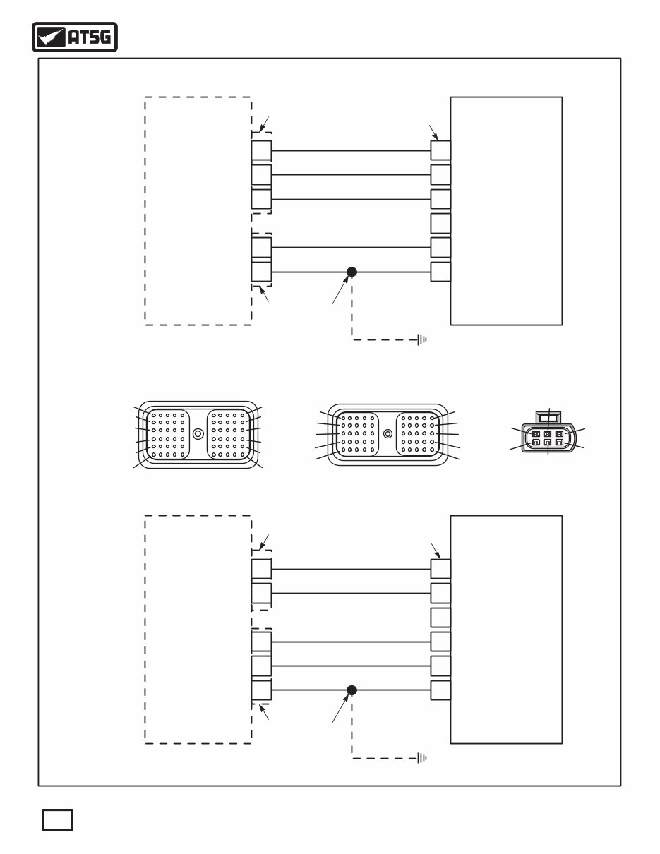
TRANSMISSION THROTTLE VALVE ACTUATOR
PARTIAL ELECTRICAL SCHEMATIC
1
2 6
5
3
4
2005
Diesel Models
Only
Connector
Views For
All Diesel
(2004-Up)
2006-Up
Diesel Models
Only
ECM - C2
50-Way Connector
(Face View)
ECM - C1
60-Way Connector
(Face View)
10
20
30
40
50
60
1
11
21
31
41
51
Note: numbers are marked
on connector
1
11
21
31
41
10
20
30
40
50
Note: numbers are marked
on connector
TTVA
6-Way Connector
(Face View)
Figure 10
35 1
20 5
6 24
23 2
8 3
4
5 VOLT SUPPLY
5 VOLT SPLY
TTVA POSITION SENS SIG
TTVA POSITION SENS SIG
NOT USED
TTVA MOTOR (+) TTVA MOTOR (+)
TTVA MOTOR (-) TTVA MOTOR (-)
SENSOR GND
ENGINE CONTROL SYSTEM
SENSOR GND
Transmission
Throttle Valve
Acuator (TTVA)
2005 ECM
Dk Blue/Dk Green
Yellow/Pink
Tan/Yellow
Orange
Tan/Orange
Dk Blue/Dk Green
Dk Blue/Dk Green
C2
Conn
Top Front Of
Transmission
C1
Conn
TTVA
Conn
27 1
20 5
6 24
23 2
8 3
4
5 VOLT SUPPLY
5 VOLT SPLY
TTVA POSITION SENS SIG
TTVA POSITION SENS SIG
NOT USED
TTVA MOTOR (+) TTVA MOTOR (+)
TTVA MOTOR (-) TTVA MOTOR (-)
SENSOR GND
ENGINE CONTROL SYSTEM
SENSOR GND
Transmission
Throttle Valve
Acuator (TTVA)
2006-UP ECM
Yellow/Pink
Tan/Yellow
Orange
Tan/Orange
Dk Blue/Dk Green Dk Blue/Dk Green
Dk Blue/Dk Green
Top Front Of
Transmission
C2
Conn
C1
Conn TTVA
Conn
{
{
{
10
AUTOMATIC TRANSMISSION SERVICE GROUP
Technical Service Information
Copyright © 2011 ATSG
You're Reading a Preview
What's Included?
Fast Download Speeds
Online & Offline Access
Access PDF Contents & Bookmarks
Full Search Facility
Print one or all pages of your manual
$41.99
Viewed 73 Times Today


Secure transaction
What's Included?
Fast Download Speeds
Online & Offline Access
Access PDF Contents & Bookmarks
Full Search Facility
Print one or all pages of your manual
$41.99
This workshop repair manual provides comprehensive information for servicing the 46RE automatic transmission. It is a valuable resource for both professional mechanics and DIY enthusiasts.


