

Dodge Neon 1998 Factory Service Repair Manual
What's Included?
Fast Download Speeds
Offline Viewing
Access Contents & Bookmarks
Full Search Facility
Print one or all pages of your manual
STARTING
CONTENTS
page page
GENERAL INFORMATION
BOSCH STARTER ........................ 1
INTRODUCTION ......................... 1
SUPPLY CIRCUIT AND CONTROL CIRCUIT .... 1
DIAGNOSIS AND TESTING
FEED CIRCUIT RESISTANCE TEST ........... 2
FEED CIRCUIT TEST ...................... 2
STARTER CONTROL CIRCUIT .............. 1
STARTING SYSTEM TEST ................. 4
REMOVAL AND INSTALLATION
SAFETY SWITCHES ...................... 6
STARTER RELAY ........................ 7
STARTER .............................. 6
SPECIFICATIONS
STARTER .............................. 7
TORQUE ............................... 7
GENERAL INFORMATION
INTRODUCTION
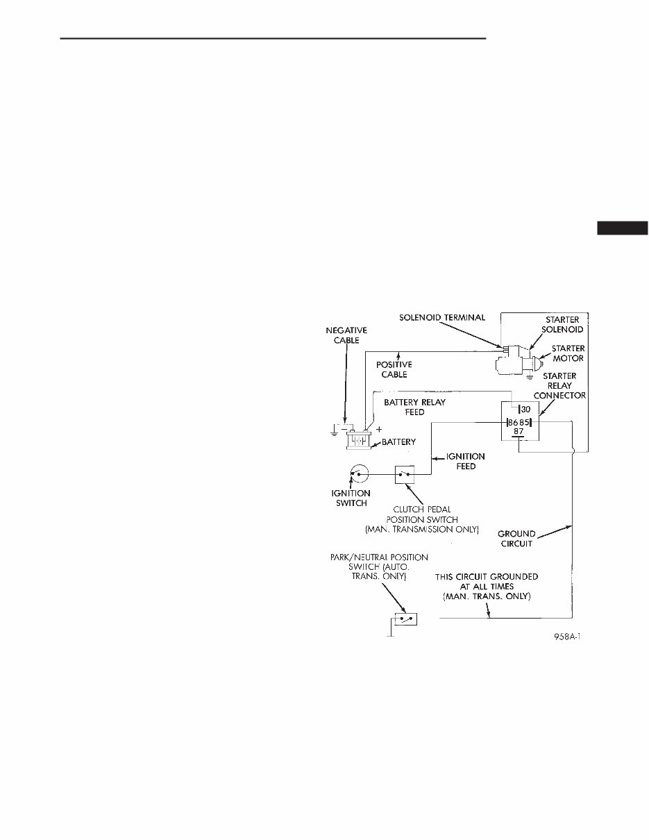
The starting system (Fig. 1) has:
• Ignition switch
• Starter relay
• Neutral starting and back up switch
• Clutch pedal position switch
• Wiring harness
• Battery
• Starter motor with an integral solenoid
BOSCH STARTER
The Bosch is a permanent magnet starter motor. A
planetary gear train transmits power between starter
motor and pinion shaft. The fields have six perma-
nent magnets. The starter system consists of two
separate circuits:
• A high amperage supply to feed the starter
motor.
• A low amperage circuit to control the starter
solenoid.
SUPPLY CIRCUIT AND CONTROL CIRCUIT
The starter system consists of two separate cir-
cuits:
• A high amperage supply to feed the starter
motor.
• A low amperage circuit to control the starter
solenoid.
DIAGNOSIS AND TESTING
STARTER CONTROL CIRCUIT
The starter control circuit has:
• Starter solenoid
• Starter relay
• Neutral starting and back up switch with auto-
matic transmissions
• Clutch pedal position switch with manual trans-
mission
• Ignition switch
• Battery
• All related wiring and connections
CAUTION: Before performing any starter tests, the
ignition and fuel systems must be disabled.
Fig. 1 Starting System
PL STARTING 8B - 1
To disable the ignition and fuel systems, disconnect
the Automatic Shutdown Relay (ASD). The ASD relay
is located in the Power Distribution Center (PDC).
Refer to the PDC cover for proper relay location.
FEED CIRCUIT RESISTANCE TEST
Before proceeding with this operation, review Diag-
nostic Preparation and Starter Feed Circuit Tests.
The following operation will require a voltmeter,
accurate to 1/10 of a volt.
CAUTION: Ignition system also must be disabled
to prevent engine start while performing the follow-
ing tests.
(1) To disable the ignition and fuel systems, dis-
connect the Automatic Shutdown Relay (ASD). The
ASD relay is located in the Power Distribution Cen-
ter (PDC). Refer to the PDC cover for proper relay
location.
(2) With all wiring harnesses and components
properly connected, perform the following:
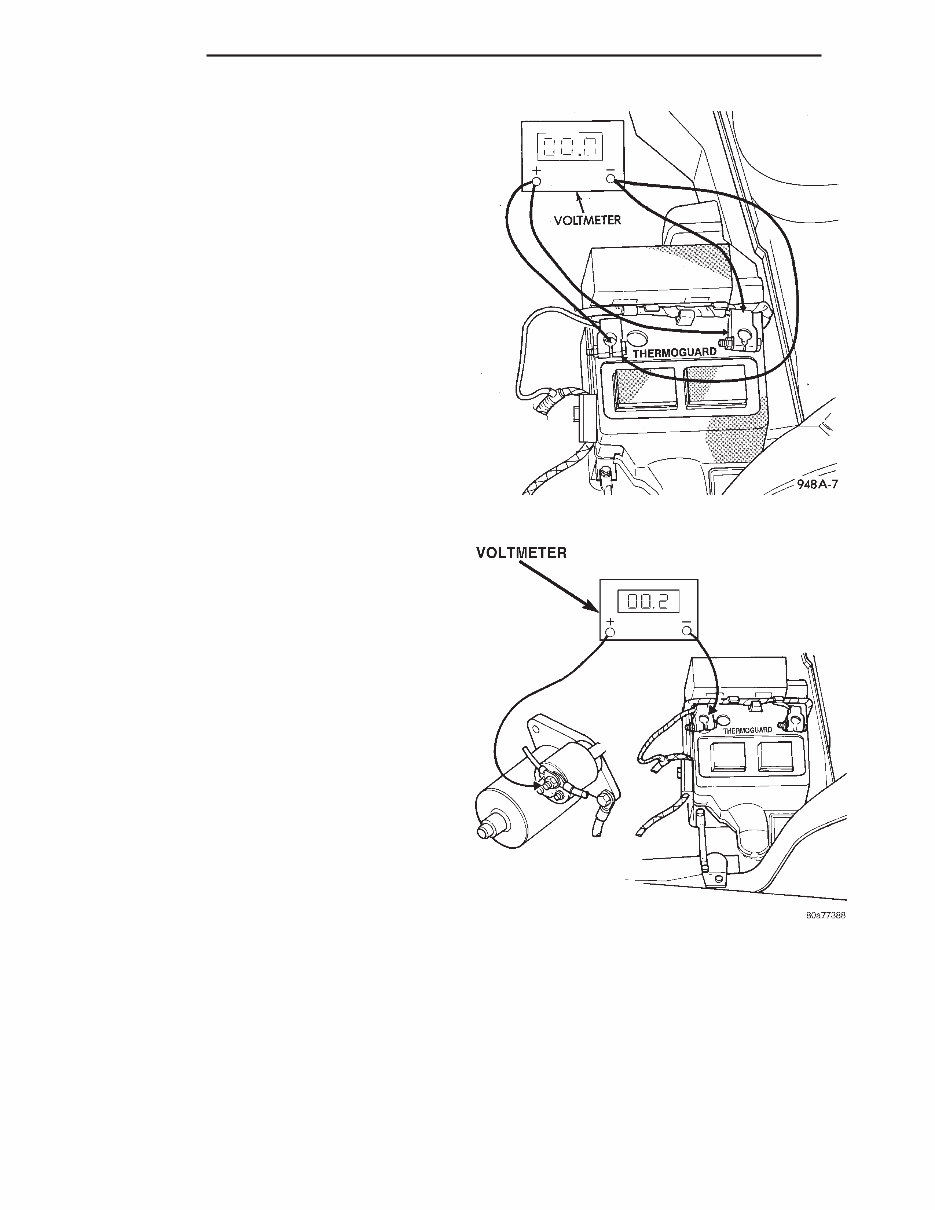
(a) Connect the negative lead of the voltmeter to
the battery negative post, and positive lead to the
battery negative cable clamp (Fig. 2). Rotate and
hold the ignition switch in the START position.
Observe the voltmeter. If voltage is detected, cor-
rect poor contact between cable clamp and post.
(b) Connect positive lead of the voltmeter to the
battery positive post, and negative lead to the bat-
tery positive cable clamp (Fig. 2). Rotate and hold
the ignition switch key in the START position.
Observe the voltmeter. If voltage is detected, cor-
rect poor contact between the cable clamp and
post.
(c) Connect negative lead of voltmeter to battery
negative terminal, and positive lead to engine
block near the battery cable attaching point (Fig.
3). Rotate and hold the ignition switch in the
START position. If voltage reads above 0.2 volt,
correct poor contact at ground cable attaching
point. If voltage reading is still above 0.2 volt after
correcting poor contacts, replace ground cable.
(3) Connect positive voltmeter lead to the starter
motor housing and the negative lead to the battery
negative terminal (Fig. 4). Hold the ignition switch
key in the START position. If voltage reads above 0.2
volt, correct poor starter to engine ground.
(a) Connect the positive voltmeter lead to the
battery positive terminal, and negative lead to bat-
tery cable terminal on starter solenoid (Fig. 5).
Rotate and hold the ignition switch in the START
position. If voltage reads above 0.2 volt, correct
poor contact at battery cable to solenoid connec-
tion. If reading is still above 0.2 volt after correct-
ing poor contacts, replace battery positive cable.
(b) If resistance tests do not detect feed circuit
failures, replace the starter motor.
FEED CIRCUIT TEST
The following procedure will require a suitable
volt-ampere tester (Fig. 6).
CAUTION: Before performing any starter tests, the
ignition and fuel systems must be disabled.
Fig. 2 Test Battery Connection Resistance
Fig. 3 Test Ground Circuit Resistance
8B - 2 STARTING PL
DIAGNOSIS AND TESTING (Continued)
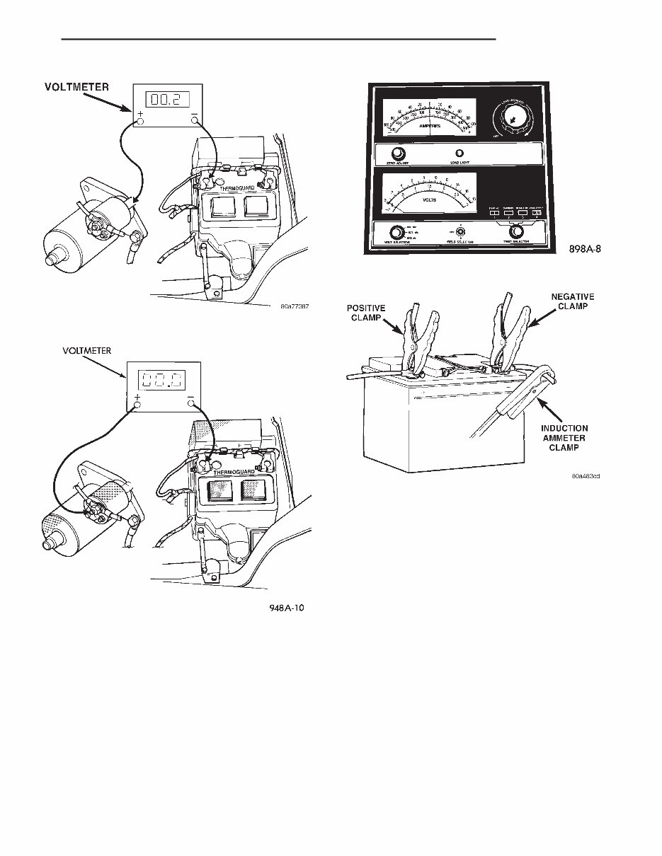
(1) Connect a volt-ampere tester to the battery ter-
minals (Fig. 7). Refer to the operating instructions
provided with the tester being used.
(2) To disable the ignition and fuel systems, dis-
connect the Automatic Shutdown Relay (ASD). The
ASD relay is located in the Power Distribution Cen-
ter (PDC). Refer to the PDC cover for proper relay
location. The 2.5L Diesel Engine, to disable the
engine from starting, disconnect wire connector from
the Fuel Solenoid.
(3) Verify that all lights and accessories are OFF,
and the transmission shift selector is in the PARK
position or with the clutch pedal depressed and SET
parking brake.
CAUTION: Do not overheat the starter motor or
draw the battery voltage below 9.6 volts during
cranking operations.
(4) Rotate and hold the ignition switch in the
START position. Observe the volt-ampere tester (Fig.
6).
• If voltage reads above 9.6 volts, and amperage
draw reads above 280 amps or the Diesel engine
above 450 amps, check for engine seizing or faulty
starter.
• If voltage reads 12.4 volts or greater and amper-
age reads 0 to 10 amps, check for corroded cables
and/or bad connections.
• Voltage below 9.6 volts and amperage draw
above 300 amps or Diesel engine above 500 amps,
the problem is the starter. Replace the starter refer
to starter removal.
(5) After the starting system problems have been
corrected, verify the battery state-of-charge and
Fig. 6 Volt Ampere Tester
Fig. 7 Volt-Ampere Tester Connections
Fig. 4 Test Starter Motor Ground
Fig. 5 Test Battery Positive Cable Resistance
PL STARTING 8B - 3
DIAGNOSIS AND TESTING (Continued)

charge battery if necessary. Disconnect all testing
equipment and connect ASD relay or the Fuel Sole-
noid. Start the vehicle several times to assure the
problem has been corrected.
STARTING SYSTEM TEST
For circuit descriptions and diagrams, refer to
8W-21, Starting System in Group 8W, Wiring Dia-
grams.
WARNING: ON VEHICLES EQUIPPED WITH AIR-
BAGS, REFER TO GROUP 8M - PASSIVE
RESTRAINT SYSTEMS BEFORE ATTEMPTING
STEERING WHEEL, STEERING COLUMN, OR
INSTRUMENT PANEL COMPONENT DIAGNOSIS OR
SERVICE. FAILURE TO TAKE THE PROPER PRE-
CAUTIONS COULD RESULT IN ACCIDENTAL AIR-
BAG DEPLOYMENT AND POSSIBLE PERSONAL
INJURY.
INSPECTION
Before removing any unit from the starting system
for repair or diagnosis, perform the following inspec-
tions:
• Battery - Visually inspect the battery for indi-
cations of physical damage and loose or corroded
cable connections. Determine the state-of-charge and
cranking capacity of the battery. Charge or replace
the battery, if required. Refer to Group 8A, Battery
for more information.
• Ignition Switch - Visually inspect the ignition
switch for indications of physical damage and loose
or corroded wire harness connections.
• Clutch Pedal Position Switch - Visually
inspect the clutch pedal position switch for indica-
tions of physical damage and loose or corroded wire
harness connections.
• Park/Neutral Position Switch - Visually
inspect the park/neutral position switch for indica-
tions of physical damage and loose or corroded wire
harness connections.
• Starter Relay - Visually inspect the starter
relay for indications of physical damage and loose or
corroded wire harness connections.
• Starter - Visually inspect the starter for indica-
tions of physical damage and loose or corroded wire
harness connections.
• Starter Solenoid - Visually inspect the starter
solenoid for indications of physical damage and loose
or corroded wire harness connections.
• Wiring - Visually inspect the wire harness for
damage. Repair or replace any faulty wiring, as
required.
8B - 4 STARTING PL
DIAGNOSIS AND TESTING (Continued)

STARTING SYSTEM DIAGNOSIS
CONDITION POSSIBLE CAUSE CORRECTION
STARTER FAILS TO
ENGAGE.
1. Battery discharged or faulty.
2. Starting circuit wiring faulty.
3. Starter relay faulty.
4. Ignition switch faulty.
5. Park/Neutral position switch
(auto trans) faulty or mis-adjusted.
6. Clutch pedal position switch
(man trans) faulty.
7. Starter solenoid faulty.
8. Starter assembly faulty.
1. Refer to Group 8A, Battery. Charge or replace
battery, if required.
2. Refer to Feed Circuit Resistance Test and
Feed Circuit Test in this section.
3. Refer to Relay Test, in this section. Replace
relay, if necessary.
4. Refer to Ignition Switch Test, in Group 8D
Ignition System or Group 8W, Wiring Diagrams.
Replace switch, if necessary.
5. Refer Park/Neutral Position Switch Test, in
Group 21, Transaxle. Replace switch, if
necessary.
6. Refer to Clutch Pedal Position Switch Test, in
Group 6, Clutch. Replace switch, if necessary.
7. Refer to Solenoid Test, in this section.
Replace starter assembly, if necessary.
8. If all other starting system components and
circuits check OK, replace starter assembly.
STARTER ENGAGES,
FAILS TO TURN
ENGINE.
1. Battery discharged or faulty.
2. Starting circuit wiring faulty.
3. Starter assembly faulty.
4. Engine seized.
1. Refer to Group 8A, Battery. Charge or replace
battery as necessary.
2. Refer to the Feed Circuit Resistance Test and
the Feed Circuit Test in this section. Repair as
necessary.
3. If all other starting system components and
circuits check OK, replace starter assembly.
4. Refer to Group 9 Engine, for diagnostic and
service procedures.
STARTER ENGAGES,
SPINS OUT BEFORE
ENGINE STARTS.
1. Broken teeth on starter ring gear.
2. Starter assembly faulty.
1. Remove starter. Inspect ring gear and replace
if necessary.
2. If all other starting system components and
circuits check OK, replace starter assembly.
STARTER DOES NOT
DISENGAGE.
1. Starter improperly installed.
2. Starter relay faulty.
3. Ignition switch faulty.
4. Starter assembly faulty.
1. Install starter. Tighten starter mounting
hardware to correct torque specifications.
2. Refer to Relay Test, in this section. Replace
relay, if necessary.
3. Refer to Ignition Switch Test, in Group 8D,
Ignition System. Replace switch, if necessary.
4. If all other starting system components and
circuits check OK, replace starter assembly.
PL STARTING 8B - 5
DIAGNOSIS AND TESTING (Continued)
You're Reading a Preview
What's Included?
Fast Download Speeds
Offline Viewing
Access Contents & Bookmarks
Full Search Facility
Print one or all pages of your manual
$36.99
Viewed 79 Times Today


Secure transaction
What's Included?
Fast Download Speeds
Offline Viewing
Access Contents & Bookmarks
Full Search Facility
Print one or all pages of your manual
$36.99
A Dodge Neon 1998 Repair/Service Manual is available, offering detailed instructions and step-by-step diagrams for all workshop procedures. This comprehensive manual covers everything from changing plugs to electrical diagrams, torque settings, and fluid capacities. It is designed for use by both professional mechanics and DIY enthusiasts, providing all the necessary information in a user-friendly format.
The manual covers a wide range of topics, including but not limited to:
- Introduction
- Lubrication and Maintenance
- Suspension
- Differential and Driveline
- Brakes
- Clutch
- Cooling System
- Battery
- Starting Systems
- Charging System
- Ignition System
- Instrument Panel Systems
- Audio Systems
- Horn Systems
- Speed Control System
- Turn Signal and Hazard Warning Systems
- Wiper and Washer Systems
- Lamps
- Passive Restraint Systems
- Electrically Heated Systems
- Power Distribution Systems
- Power Lock Systems
- Vehicle Theft/Security Systems
- Power Seat Systems
- Power Window Systems
- Power Mirror Systems
- Chime/Buzzer Warning Systems
- Overhead Console Systems
- Wiring Diagrams
- Engine
- Exhaust System
- Frame and Bumpers
- Fuel System
- Steering
- Transmission and Transfer Case
- Tires and Wheels
- Body
- Heating and Air Conditioning
- Emission Control Systems
The manual is available in PDF format and can be viewed using Adobe Reader on both Windows and Mac operating systems. It allows for easy zooming in and out to facilitate clear viewing of diagrams and instructions.


