ENGINES CONTENTS page page 3. 3L ENGINE .......................... 12 3. 5L ENGINE .......................... 48 ENGINE DIAGNOSIS ...................... 7 STANDARD SERVICE INFORMATION ........ 1 STANDARD SERVICE INFORMATION INDEX page page GENERAL INFORMATION CHECKING ENGINE OIL LEVEL ............. 3 ENGINE OIL SERVICE .................... 4 ENGINE PERFORMANCE ................. 2 FORM-IN-PLACE GASKETS ................ 1 MEASURING MAIN BEARING AND CONNECTING ROD BEARING CLEARANCES ........................ 2 SERVICE PROCEDURES ENGINE CORE PLUGS ................... 6 HONING CYLINDER BORES ............... 5 HYDROSTATIC LOCKED ENGINE ........... 5 REPAIR OF DAMAGED OR WORN THREADS .. 5 GENERAL INFORMATION FORM-IN-PLACE GASKETS There are numerous places where form-in-place gaskets are used on theengine. Care must be taken when applying form-in-place gaskets to assure obtaining the desired results. Do not use form-in- place gasket material unless specified. Bead size, continuity , and location are of great importance. T oo thin a bead can result in leakage while too much can result in spill-over which can break off and obstruct fluid feed lines. A continuous bead of the proper width is essential toobtain a leak-free gaskets. There are numerous types of form-in-place gasket materials are used in the engine area. Mopar Sili- cone Rubber Adhesive Sealant and Mopar Gasket Maker gasket materials, eachhave different proper- ties and cannot be used in place of the other . MOPAR SILICONE RUBBER ADHESIVE SEALANT Mopar Silicone Rubber Adhesive Sealant or equiv- alent, normally black in color , is available in three ounce tubes. Moisture in the air causes the Mopar Silicone Rubber Adhesive Sealant material tocure. This material is normally used on flexible metal flanges. It has a shelf life of one year and will not properly cure ifover age. Always inspectthe package for theexpiration date before use. MOPAR GASKET MAKER Mopar Gasket Maker is an anaerobic type gasket material. The material cures in the absence of air when squeezed between two metallic surfaces. It will not cure if left in the uncovered tube. The anaerobic material is for use between two machined surfaces. Do not use on flexible metal flanges. GASKET DISASSEMBLY Parts assembled with form-in-place gaskets may be disassembled without unusual effort. In some instances, it may be necessary to lightly tap the part with a mallet or other suitable tool to break the seal between the mating surfaces. Aflat gasket scraper may also be lightly tapped into the joint but care must be takennotto damage the mating surfaces. SURFACE PREPARATION Scrape clean or wire brush all gasket surfaces removing all loose material. Inspect stampedparts to assure gasket rails are flat. Flatten rails with a ham- mer on a heavy steel plate if required. Gasket sur- faces must be free of oil and dirt. Make sure old gasket material is removed from blind attaching holes. LH ENGINES 9 - 1
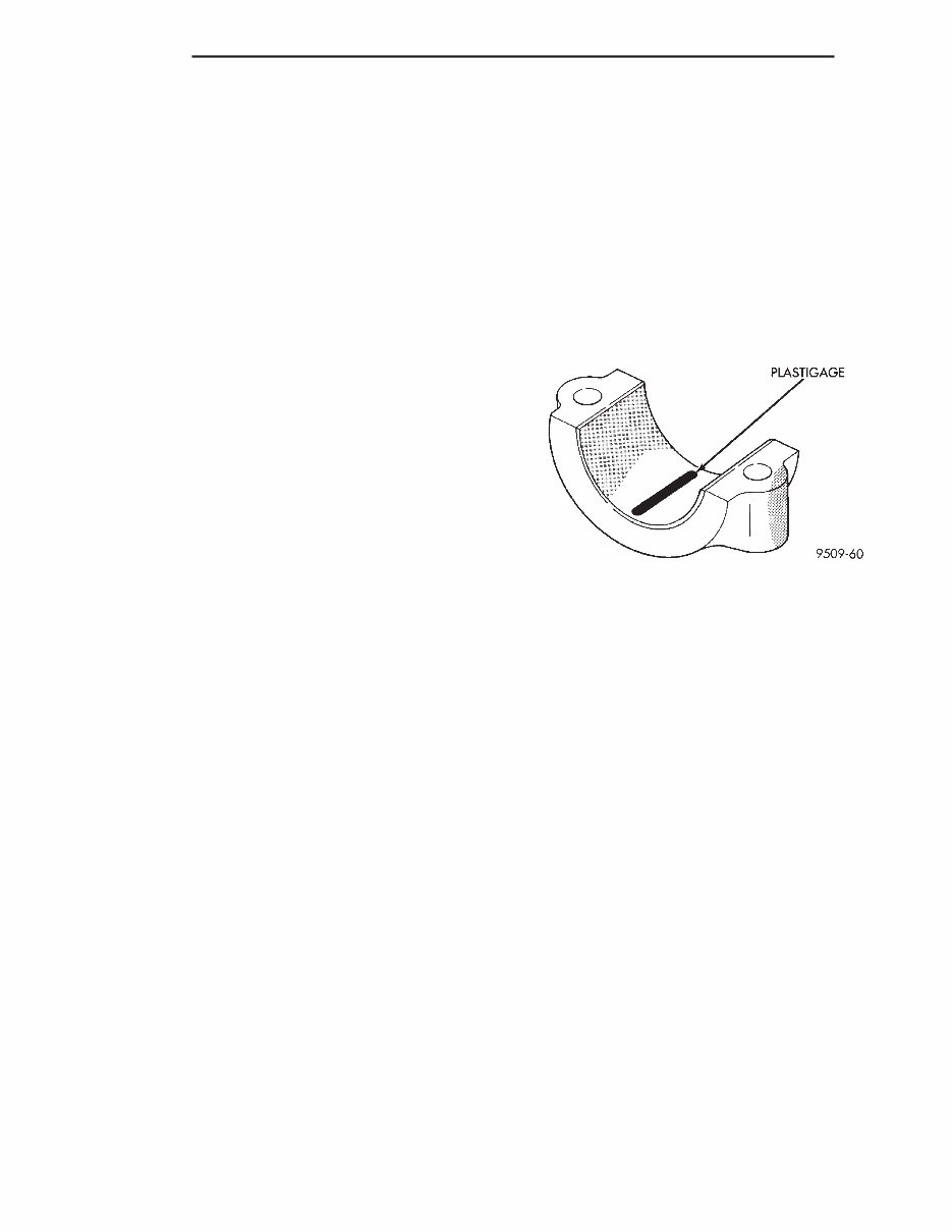
FORM-IN-PLACE GASKET APPLICATION Assembling parts using a form-in-place gasket requires care but it’s easier thenusing precut gas- kets. Mopar Gasket Maker material should be applied sparingly 1 mm (0.040 inch.) diameter or less of seal- anttoone gasket surface. Be certain the material surrounds each mounting hole. Excess material can easily be wiped off. Componentsshould be torqued in place within 15 minutes. The use of a locating dowel is recommended during assembly to prevent smear- ing material off the location. The Mopar Silicone Rubber Adhesive Sealant gas- ket material or equivalent should be applied in a con- tinuous bead approximately 3 mm (0.120 inch) in diameter . All mounting holes must be circled. For corner sealing, a 3.17 or 6.35 mm (1/8 or 1/4 inch.) drop is placed in the center of the gasket contact area. Uncured sealant may be removed with a shop towel. Componentsshould be torqued in place while the sealant isstill wetto the touch (within 10 min- utes). The usage of a locating dowelis recommended during assembly to prevent smearing material off the location. ENGINE PERFORMANCE If a loss of performance is noticed, ignition timing should be checked. If ignition timing is retarded by 9, 18 or 27° “it indicates” 1, 2 or 3 (timing belt or chain) teeth may have skipped. The camshaft and crank- shafttiming should be checked. Refer to Engine Tim- ing Sprockets and Oil Seals of the Engine Section. T o provide best vehicle performance and lowest vehicle emissions, it is most important that the tune-up be done accurately . Use the specifications listed on the V ehicle Emission Control Information label found in theengine compartment. (1) T est cranking amperage draw. See Starting Motor Cranking Amperage Draw ElectricalSection of this manual. (2) Tighten the intake manifold bolts to specifica- tions. (3) Perform cylinder compression test. See diagno- sis and testing in thissection. (4) Clean orreplace spark plugs as necessary and adjust gap asspecified in Electrical Group 8. Tighten to specifications. (5) T est resistance of spark plug cables. Refer to Ignition System Secondary Circuit Inspection Electri- calSection Group 8. (6) Inspectthe primary wire. T est coil output volt- age, primary and secondary resistance. Replace parts as necessary . Refer to Ignition System and make nec- essary adjustment. (7) T est fuel pump for correct pressure. Refer to FuelSystem Group 14, Specifications. (8) The air filter elements should be replaced as specified in Lubrication and Maintenance, Group 0. (9) Inspect crankcase ventilation system as out lined in Lubrication and Maintenance, Group 0. For emission controlssee Emission Controls Group 25 for service procedures. (10) Inspect and adjust accessory belt drives refer- ring to Accessory Belt Drive in Cooling System, Group 7 for proper adjustments. (11) Road test vehicle as a final test. MEASURING MAIN BEARING AND CONNECTING ROD BEARING CLEARANCES PLASTIGAGE METHOD Engine crankshaft bearing clearances can be deter- mined by use of Plastigage or equivalent. The follow- ing is the recommended procedure for the use of Plastigage: NOTE: The total clearance of the main bearings can only be determined by removing the weight of the crankshaft. This can be accomplished by either of two methods: PREFERRED METHOD Shimming the bearings adjacentto the bearing to be checked in order to remove the clearance between upper bearing shell and the crankshaft. This can be accomplished by placing a minimum of 0.254 mm (0.010 in.) shim (e. g. cardboard, matchbook cover , etc.) between the bearing shell and the bearing cap on the adjacent bearings and tightening bolts to 14-20 N·m (10-15 ft. lbs.). The number of main bear- ing will vary from engine to engine. ENGINE WITH 5 MAIN BEARINGS • When checking #1 main bearing shim #2 main bearing. • When checking #2 main bearing shim #1 & 3 main bearing. • When checking #3 main bearing shim #2 & 4 main bearing. Fig. 1 Plastigage Placed in Lower Shell PLASTIGAGE 9 - 2 ENGINES LH GENERAL INFORMATION (Continued)
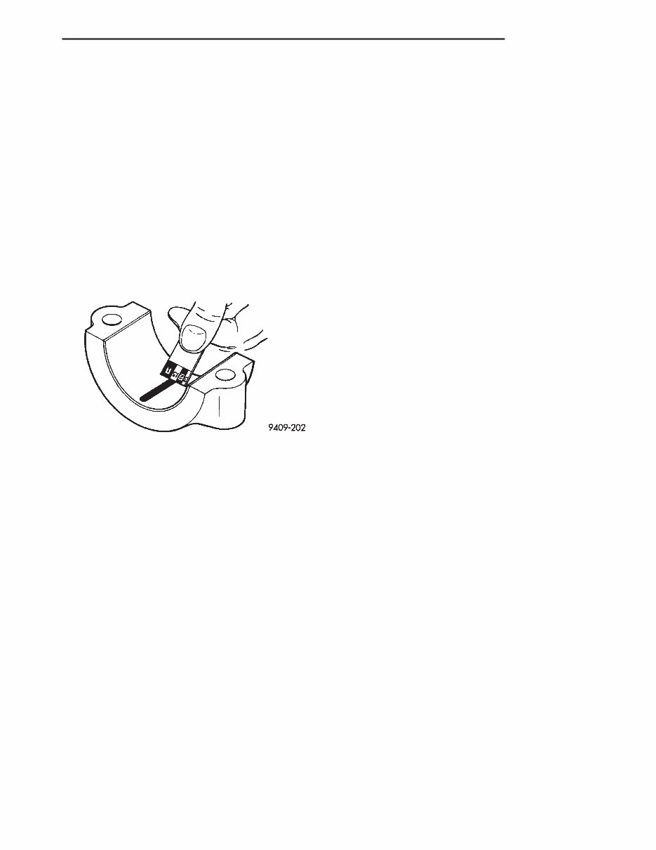
• When checking #4 main bearing shim #3 & 5 main bearing. • When checking #5 main bearing shim #4 main bearing. ENGINE WITH 4 MAIN BEARING • When checking #1 main bearing shim #2 main bearing. • When checking #2 main bearing shim #1 & #3 main bearing. • When checking #3 main bearing shim #2 & #4 main bearing. • When checking #4 main bearing shim #3 main bearing. NOTE: REMOVE ALL SHIMS BEFORE REASSEM- BLING ENGINE ALTERNATIVE METHOD The weight of the crankshaft can be supported by a jack under the counterweight adjacentto the bearing being checked. PLASTIGAGE PROCEDURE (1) Remove oil film from surface to be checked. Plastigage issoluble in oil. (2) Place a piece of Plastigage across the entire width of the bearing shell in the cap approximately 6.35 mm (1/4 in.) off center and away from the oil holes (Fig. 1). (In addition, suspected areas can be checked by placing the Plastigage in the suspected area). T orque the bearing cap bolts of the bearing being checked to the proper specifications. (3) Remove the bearing cap and compare the width of the flattened Plastigage (Fig. 2) with the metric scale provided on the package. Locate the band closestto the same width. This band shows the amount of clearance in thousandths of a millimeter . Differences in readings between theends indicate the amount of taper present. Record all readings taken. Refer to Engine Specifications. Plastigage gener- ally is accompanied by two scales. Onescale is in inches, the other is a metric scale. NOTE: Plastigage is available in a variety of clear- ance ranges. Use the most appropriate range for the specifications you are checking. CONNECTING ROD BEARING CLEARANCE Engine connecting rod bearing clearances can be determined by use of Plastigage or equivalent. The following is the recommendedprocedure for the use of Plastigage: (1) Rotate the crankshaft until the connecting rod to be checked is atthe bottom of itsstroke. (2) Remove oil film from surface to be checked. Plastigage issoluble in oil. (3) Place a piece of Plastigage across the entire width of the bearing shell in the bearing cap approx- imately 6.35 mm (1/4 in.) off center and away from the oil hole (Fig.1). In addition, suspect areas can be checked by placing plastigage in the suspect area. (4)Assemble the rod cap with Plastigage in place. Tighten the rod cap to the specified torque. Do not rotate the crankshaft while assembling the cap orthe Plastigage may besmeared, giving inac- curate results. (5) Remove the bearing cap and compare the width of the flattened Plastigage (Fig. 2) with the scale provided on the package. Locate the band clos- est to the same width. This band indicates the amount of oil clearance. Differences in readings between the ends indicate the amount of taper present. Record all readings taken. Refer to Engine Specifications. Plastigage generally is accompa- nied by two scales. Onescale is in inches, the other is a metric scale. If the bearing clearance exceeds 0.076 mm (0.003 in.) replace bearing. NOTE: Plastigage is available in a variety of clear- ance ranges. Use the most appropriate range for the specifications you are checking. CHECKING ENGINE OILLEVEL The besttime tocheck engine oil levelis after it hassat overnight, or if theengine has been running, allow theengine to be shut off for at least 5 minutes before checking oil level. Checking the oil while the vehicle is on level ground will improve the accuracy of the oil level reading. Add only when the levelis at or below the ADD mark. Fig. 2 Clearance Measurement LH ENGINES 9 - 3 GENERAL INFORMATION (Continued)
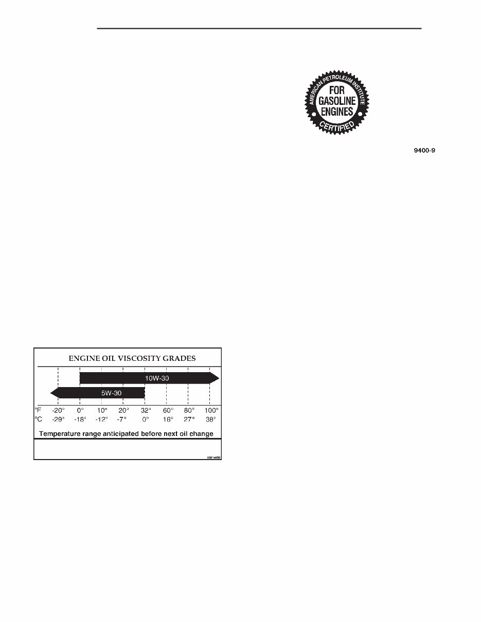
ENGINE OIL SERVICE WARNING: NEW OR USED ENGINE OIL CAN BE IRRITATING TO THE SKIN. AVOID PROLONGED OR REPEATED SKIN CONTACT WITH ENGINE OIL. CONTAMINANTS IN USED ENGINE OIL, CAUSED BY INTERNAL COMBUSTION, CAN BE HAZARDOUS TO YOUR HEALTH. THOROUGHLY WASH EXPOSED SKIN WITH SOAP AND WATER. DO NOT WASH SKIN WITH GASOLINE, DIESEL FUEL, THINNER, OR SOLVENTS, HEALTH PROBLEMS CAN RESULT. DO NOT POLLUTE, DISPOSE OF USED ENGINE OIL PROPERLY. CONTACTYOUR DEALER OR GOVERN- MENT AGENCY FOR LOCATION OF COLLECTION CENTER IN YOUR AREA. API SERVICE GRADE CERTIFIED Use an engine oil that is API Service Grade Certi- fied or an oil that conforms to the API Service Grade SH or SH/CD. MOPAR provides engine oils that con- form to all of these service grades. SAE VISCOSITY An SAE viscositygrade is used to specify the vis- cosity of engine oil. SAE 30 specifies a single viscos- ity engine oil. Engine oils also have multiple viscosities. These are specified with a dualSAE vis- cositygrade which indicates the cold-to-hottempera- ture viscosity range. Select an engine oil that is best suited to your particular temperature range and vari- ation (Fig.3). ENERGY CONSERVING OIL An Energy Conserving type oil is recommended for gasoline engines. They are designated as either ENERGY CONSERVING or ENERGY CONSERV- ING II. CONTAINER IDENTIFICATION Standard engine oil identification notations have been adopted to aid in the proper selection of engine oil. The identifying notations are located on the label of engine oil plastic bottles and the top of engine oil cans (Fig.4). ENGINE OIL CHANGE Change engine oil at mileage and time intervals described in the Maintenance Schedule. TO CHANGEENGINE OIL Run engine until achieving normal operating tem- perature. (1) Position the vehicle on a level surface and turn engine off. (2) Hoist and support vehicle on safety stands. Refer to Hoisting and Jacking Recommendations. (3) Remove oil fill cap. (4) Place a suitable drain pan under crankcase drain. (5) Remove drain plug from crankcase and allow oil to drain into pan. Inspect drain plug threads for stretching or other damage. Replace drain plug and gasket if damaged. (6) Install drain plug in crankcase. (7) Lower vehicle and fill crankcase with specified type and amount of engine oil described in thissec- tion. (8) Install oil fill cap. (9) Start engine and inspect for leaks. (10) Stop engine and inspect oil level. ENGINE OIL FILTER CHANGE FIL TERSPECIFICATION All engines areequipped with a high quality full- flow, disposable type oil filter . Chrysler Corporation recommends a Mopar or equivalent oil filter be used. OIL FIL TERREMOVAL Refer to Removal and Installation Section in Group 9, Engine for procedure. USED ENGINE OIL DISPOSAL Care should be exercised when disposing used engine oil after it has been drained from a vehicle engine. Refer to the WARNING listed above. Fig. 3 Temperature/Engine Oil Viscosity ENGINE OIL VISCOSITY GRADES Tem erature range antici ated before next oil change Fig. 4 Engine Oil Container Standard Notations 9 - 4 ENGINES LH GENERAL INFORMATION (Continued)
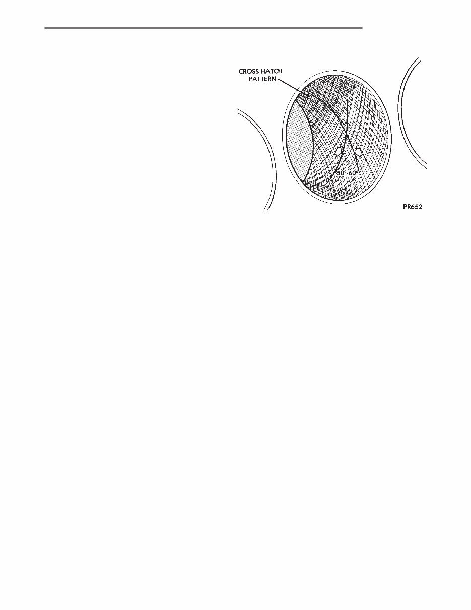
SERVICE PROCEDURES REPAIR OF DAMAGED OR WORN THREADS Damaged or worn threads (including aluminum head spark plug threads)can be repaired. Essen- tially , this repair consists of drilling out worn or damaged threads, tapping the hole with a special Heli-Coil Tap, (or equivalent) and installing an insert into the tapped hole. This brings the hole back to its original thread size. CAUTION: Be sure that the tapped holes maintain the original centerline. Heli-Coil tools and inserts are readily available from automotive parts jobbers. HONING CYLINDER BORES (1) Used carefully , the cylinder bore resizing hone C-823 equipped with 220 grit stones, is the besttool for this job. In addition to deglazing, it will reduce taper and out-of-round as well as removing light scuffing, scoring or scratches. Usually a few strokes will cleanup a bore and maintain the required lim- its. (2) Deglazing of the cylinder walls may be done using a cylinder surfacing hone, T ool C-3501, equipped with 280 grit stones, if the cylinder bore is straight and round. 20-60 strokes depending on the bore condition, will be sufficientto provide a satisfac- tory surface. Inspect cylinder walls after each 20 strokes, using a light honing oil. Do not use engine or transmission oil, mineral spirits or kerosene. (3) Honing should be done by moving the hone up and down fast enough to get a cross-hatch pattern. When hone marks intersect at 50-60 degrees, the cross hatch angle is most satisfactory for proper seat- ing of rings (Fig.5). (4) A controlled hone motor speed between 200-300 RPM is necessary toobtain the proper cross- hatch angle. The number of up anddown strokes per minute can be regulated to get the desired 50-60 degree angle. Faster up and down strokes increase the cross-hatch angle. (5) After honing, it is necessary thatthe block be cleaned again to remove all traces of abrasive. CAUTION: Ensure all abrasives are removed from engine parts after honing. It is recommended that a solution of soap and hot water be used with a brush and the parts then thoroughly dried. The bore can be considered clean when it can be wiped clean with a white cloth and cloth remains clean. Oil the bores after cleaning to prevent rusting. HYDROSTATIC LOCKED ENGINE When an engine issuspected to be hydrostatically locked, regardless of what caused the problem, these stepsshould be used. CAUTION: Do Not Use Starter Motor To Rotate Engine, severe damage may occur. (1) Inspect air cleaner , induction system and intake manifold to insure system is dry and clear of foreign material. (2) Remove negative battery cable. (3) Place a shop towel around the spark plugs when removing them from theengine. This will catch any fluid that may possibly be in the cylinder under pressure. (4) With all spark plugs removed, rotate engine crankshaft using a breaker bar and socket. (5) Identify the fluid in the cylinder(s)(i.e., cool- ant, fuel, oil or other). (6) Make sure all fluid has been removed from the cylinders. Inspect engine for damage (i.e., Connecting Rods, Pistons, V alves etc.) (7) Repair engine or components as necessary to preventthis problem from occurring again. CAUTION: Squirt approximately 1 teaspoon of oil into cylinders, rotate engine to lubricate the cylin- der walls to prevent damage on restart. (8) Install new spark plugs. (9) Drain engine oil and remove oil filter . (10) Fill engine with specified amount of approved oil and install new oil filter . (11) Connect negative battery cable. (12) Start engine and check for any leaks. Fig. 5 Cylinder Bore Cross-Hatch Pattern CROSS-HATCH PATTERN LH ENGINES 9 - 5
Introducing the 1996 DODGE INTREPID Service and Repair Manual!
This comprehensive manual is designed to assist you in maintaining and repairing your 1996 DODGE INTREPID with ease. It is a must-have for any proud owner or professional mechanic.
Featuring detailed instructions and step-by-step illustrations, this manual covers a wide range of topics, ensuring that you have all the information you need to effectively service and repair your vehicle. From basic maintenance tasks to complex repairs, this manual has got you covered.
Whether you need to change the oil, replace a broken part, or troubleshoot mechanical issues, this manual provides the guidance and expertise you need. With this manual, you can save time and money by performing repairs on your own.
Key features of the 1996 DODGE INTREPID Service and Repair Manual:
Comprehensive coverage of all major systems and components
Detailed instructions for maintenance and repair tasks
Step-by-step illustrations for easy understanding
Troubleshooting guides to identify and resolve issues
Wiring diagrams for electrical systems
Specifications and tightening torques for accurate repairs
This manual is suitable for the following models:
1996 DODGE INTREPID Base Model
1996 DODGE INTREPID ES Model
1996 DODGE INTREPID ESX Model
Invest in the 1996 DODGE INTREPID Service and Repair Manual today and take control of your vehicle's maintenance and repairs. With this manual by your side, you'll be able to keep your 1996 DODGE INTREPID running smoothly for years to come.