2001-2007 Chrysler PT Cruiser Service & Repair Manual
What's Included?
Lifetime Access
Fast Download Speeds
Offline Viewing
Access Contents & Bookmarks
Full Search Facility
Print one or all pages of your manual
GROUP TAB LOCATOR Introduction 0 Lubrication & Maintenance 2 Suspension 3 Differential & Driveline 5 Brakes 6 Clutch 7 Cooling 8A Audio/Video 8B Chime/Buzzer 8E Electronic Control Modules 8F Engine Systems 8G Heated Systems 8H Horn 8I Ignition Control 8J Instrument Cluster 8L Lamps 8M Message Systems 8N Power Systems 8O Restraints 8P Speed Control 8Q Vehicle Theft Security 8R Wipers/Washers 8T Navigation/Telecommunication 8W Wiring 9 Engine 11 Exhaust System and Turbocharger 13 Frame & Bumpers 14 Fuel System 19 Steering 21 Transaxle 22 Tires/Wheels 23 Body 24 Heating & Air Conditioning 25 Emissions Control Component and System Index Service Manual Comment Forms (Rear of Manual)
INTRODUCTION TABLE OF CONTENTS page page BODY CODE PLATE DESCRIPTION .......................... 1 FASTENER IDENTIFICATION DESCRIPTION .......................... 2 FASTENER USAGE DESCRIPTION FASTENER USAGE ..................... 5 THREADED HOLE REPAIR ............... 5 INTERNATIONAL SYMBOLS DESCRIPTION .......................... 5 METRIC SYSTEM DESCRIPTION .......................... 5 TORQUE REFERENCES DESCRIPTION .......................... 8 VEHICLE IDENTIFICATION NUMBER DESCRIPTION - VEHICLE IDENTIFICATION NUMBER ............................. 9 VEHICLE CERTIFICATION LABEL DESCRIPTION ......................... 11 E-MARK LABEL DESCRIPTION ......................... 11 VECI LABEL DESCRIPTION ......................... 11 MANUFACTURER PLATE DESCRIPTION ......................... 11 BODY CODE PLATE DESCRIPTION The Body Code Plate (Fig. 1) is located in the engine compartment on the plenum behind the right side struttower (Fig. 2). There are seven lines of information on the body code plate. Lines 4, 5, 6, and 7 are not used to define service information. Informa- tion reads from leftto right, starting with line 3 in the center of the plate to line 1 atthe bottom of the plate. BODYCODE PLATE LINE2 DIGITS 1, 2, AND 3 Paint procedure DIGIT 4 Open Space DIGITS 5THROUGH 7 Primary paint (Refer to 23 - BODY/PAINT - SPECIFICATIONS) for Body Color Codes. DIGIT 8 AND 9 Open Space DIGITS 10 THROUGH 12 Secondary Paint DIGIT 13 AND 14 Open Space DIGITS 15 THROUGH 18 Interior Trim Code DIGIT 19 Open Space Fig. 1 BODY CODE PLATE 1 - PRIMARY PAINT 2 - SECONDARY PAINT 3 - VINYL ROOF 4 - VEHICLE ORDER NUMBER 5 - CAR LINE SHELL 6 - PAINT PROCEDURE 7 - ENGINE 8 - TRIM 9 - TRANSMISSION 10 - MARKET 11 - VIN PT INTRODUCTION 1
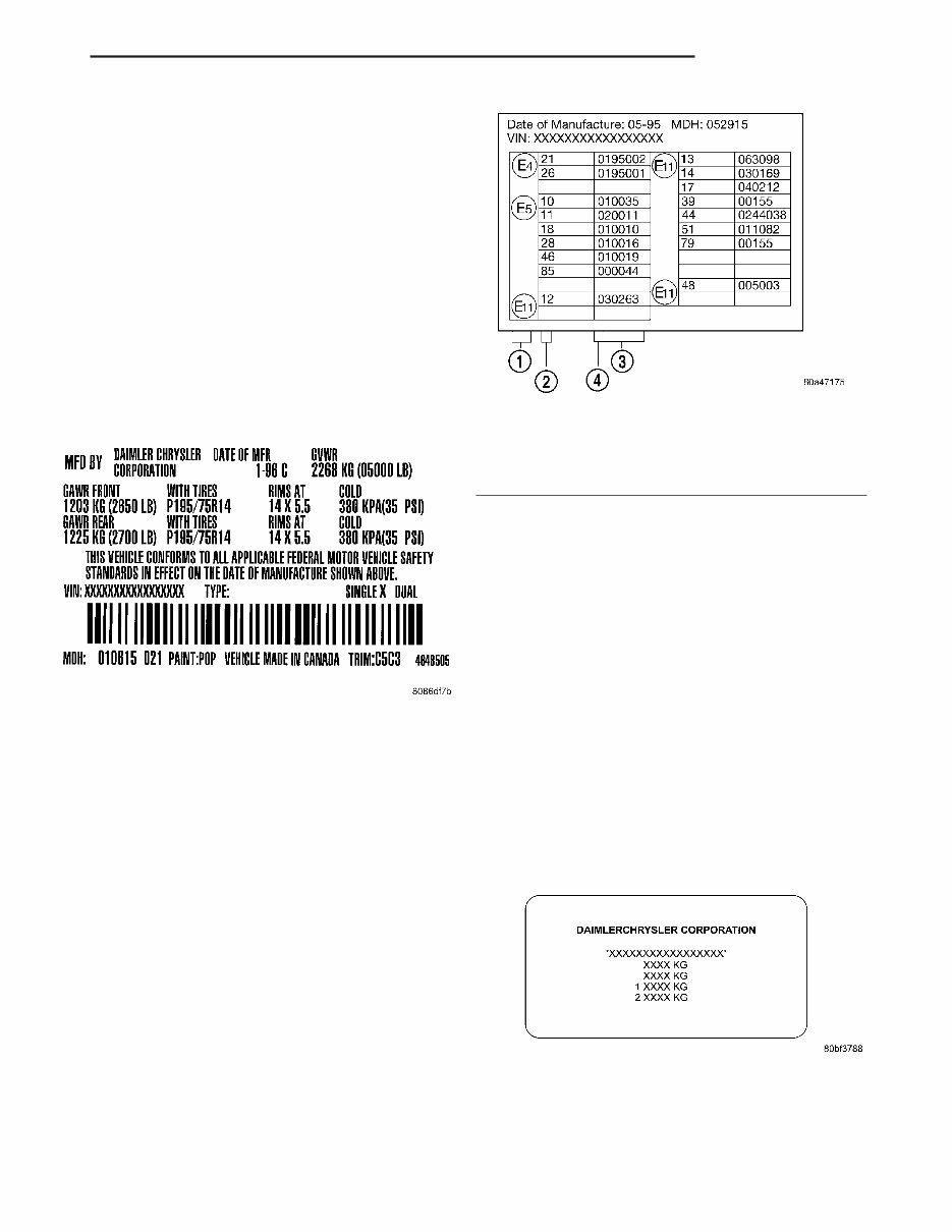
VEHICLE CERTIFICATION LABEL DESCRIPTION A vehicle certification labelis attached to the rear shutface of the driver’s door (Fig.4). This labelindi- cates date of manufacture (month and year), Gross V ehicle Weight Rating (GVWR), Gross Axle Weight Rating (GA WR) front, Gross Axle Weight Rating (GA WR) rear and the V ehicle Identification Number (VIN). The Month, Day and Hour of manufacture is also included. All communications or inquiries regarding the vehicle should include the Month-Day-Hour and V ehicle Identification Number . E-MARK LABEL DESCRIPTION An E-mark Label (Fig. 5) is located on the rear shut face of the driver’s door . The label contains the following information: • Date of Manufacture • Month-Day-Hour (MDH) • V ehicle Identification Number (VIN) • Country Codes • Regulation Number • Regulation Amendment Number • Approval Number VECI LABEL DESCRIPTION All models have a V ehicle Emission Control Infor- mation (VECI) Label. Chrysler permanently attaches the label in the engine compartment. It cannot be removed without defacing information anddestroying the label. The label contains the vehicle’s emission specifica- tions and vacuum hose routings. All hoses must be connected and routed according to the label. MANUFACTURER PLATE DESCRIPTION The Manufacturer Plate (Fig. 6) is located in the engine compartment on the passenger side rear cor- ner of the hood. The plate contains five lines of infor- mation: 1. V ehicle Identification Number (VIN) 2. Gross V ehicle Mass (GVM) 3. Gross Train Mass (GTM) 4. Gross Front Axle Rating (GFAR) 5. Gross Rear Axle Rating (GRAR) Fig. 4 VEHICLE CERTIFICATION LABEL - TYPICAL Fig. 5 E-MARK LABEL 1 - COUNTRY CODE 2 - REGULATION NUMBER 3 - APPROVAL NUMBER 4 - AMENDMENT NUMBER Fig. 6 MANUFACTURER PLATE PT INTRODUCTION 11
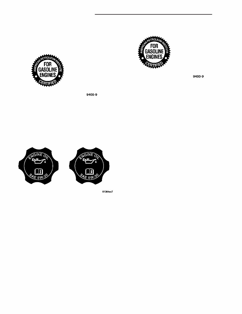
• Association des Constructeurs Européens d’ Automobiles (European Automobile Manufacturers Association) (ACEA) API CERTIFICATION AND LICENSE SYMBOL Use an engine oil that is API Certified (Fig.2) and Licensed to display the certification mark. MOPAR provides engine oils that meet or exceed, Material Standard MS-6395 requirement. SAE VISCOSITY SAE 5W-20 and SAE 5W-30 engine oils are rec- ommended for all operating temperatures. These engine oils are designed to improve low temperaturestarting and vehicle fuel economy . Referto theengine oil filler cap forthe pre- ferred engine oilviscositygrade for each vehi- cle (Fig. 3). SAE viscositygrades are used to specify the correct viscosity oil for an engine. Use only Multi- Viscosity oils such as SAE 5W-20 or 5W-30. These are specified with a dualSAE viscositygrade which indicates the cold (5W) to hot (20, 30) temperature performance range of the oil. ACEA CATEGORIES For countries that use the ACEA European Oil Categories for service fill oils, use engine oils that meet the requirements of ACEAA1/B1, A2/B2, or A3/B3. CONTAINER IDENTIFICATION The Engine Oil Certification Mark was developed and trademarked by the API to refer customers to thoseengine oils preferred by the automobile manu- facturers. Thissymbol means thatthe oil has been certified and licensed by the American Petroleum Institute (API). This certification mark will only be found on the front of the oil containers (Fig.4). Those oils that do not display the “Mark” on the front of the container should not be used. DiamlerChrysler only recommends API Certified engine oils that meetthe requirements of Material Standard MS-6395. Use Mopar or an equivalent oil meeting the specification MS-6395. SYNTHETIC ENGINE OILS There are a number of engine oils being promoted as either syntheticor semi-synthetic. If you chose to use such a product, use only those oils that are cer- tified by the American Petroleum Institute (API) to display the “Certification Mark” and show SAE vis- cosity grade recommended for each vehicle. Follow the service schedule that describes your driving type. ENGINE OIL ADDITIVES/SUPPLEMENTS The manufacturer does notrecommend the addi- tion of any engine oil additives/supplements to the specified engine oil. Engine oil additives/supplements should not be used to enhance engine oil perfor- mance. Engine oil additives/supplementsshould not be used to extend engine oil change intervals. No additive is known to be safe for engine durability and can degradeemission components. Additives can con- tain undesirable materials that harm the long term durability of engines and emission systems by: • Increasing the level of Phosphorus and Sulfur in theengine oil. The API Certified Engine Oils control the Phosphorus and Sulfur contents of the oil to lev- els that reduce the contamination effect on the vehi- cles emission control system. • Altering the viscosity characteristics of the engine oil so that it no longer meets the require- ments of the specified viscositygrade. • Creating potential for an undesirable additive compatibility interaction in the engine crankcase. Fig. 2 API Certification Mark Fig. 3 5W-30 Oil Filler Cap Fig. 4 API Certification Mark 0 - 2 LUBRICATION & MAINTENANCE PT FLUID TYPES (Continued)
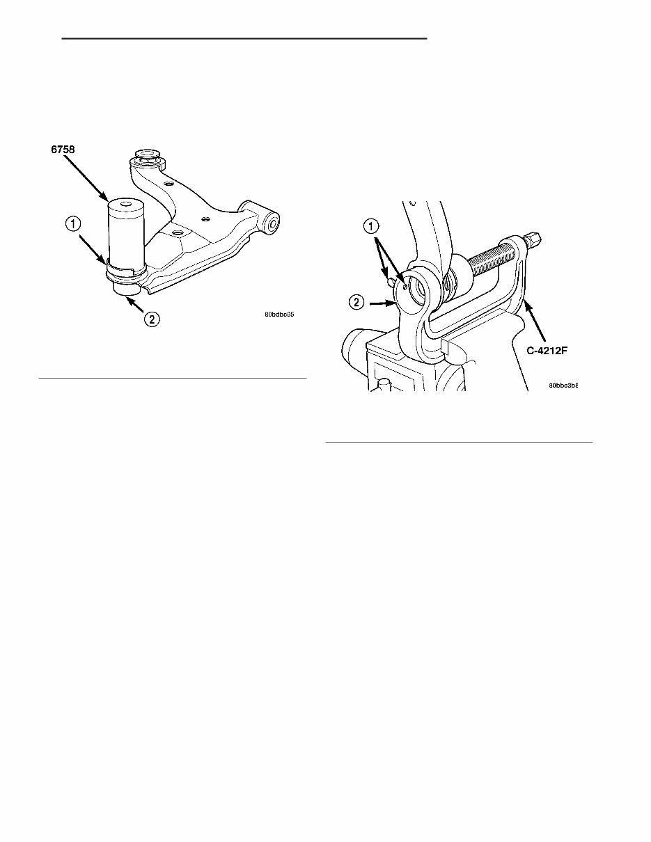
CAUTION: When installing the sealing boot on the ball joint, position the upward lip on the outside perimeter of the seal boot outward, away from the control arm once installed (Fig. 32). It is there to help shield heat from the sealing boot. (6) Place a new ball joint seal boot over the ball joint stud. The upward lip located on the outside perimeter of the seal boot must point outward away from the control arm once installed (Fig. 32). Start the sealing boot over the sides of the ball joint by hand. (7) Position the Installer , Special T ool 6758, over the sealing boot outer diameter asshown (Fig. 32). By hand, apply pressure to the top of the Installer until the seal boot is pressed squarely down against the top surface of lower control arm. (8) Remove the tool. (9) If not already installed, install standard zirc- type grease fitting in ball joint. CAUTION: It is important to lubricate the ball joint before installation of steering knuckle to allow proper venting when the seal is filled. If the ball joint is lubricated after installation to knuckle, dam- age to the seal can occur. (10) Using a hand-operatedpump grease gun, fill the ball joint seal boot with Mopar Multi-Mileage Lube or equivalent until grease pushes out past ball joint stem. Wipe off overfill. (11) Remove standard zirc-type grease fitting and install headless grease fitting from original ball joint to prevent future lubricating. See above Caution. Be sure to properly cleanheadless grease fitting priorto installation. (12) Install the lower control arm. (Refer to 2 - SUSPENSION/FRONT/LOWER CONTROL ARM - INSTALLATION). ASSEMBL Y - LOWER CONTROL ARM (REAR ISOLATOR BUSHING) (1) Back the Ball Joint Press, Special T ool C-4212F , set screw outward so it does not extend out into the cup area (Fig. 33). (2) Startthe isolator bushing into the bottom of the lower control arm bushing bore by hand. Position the bushing so the voids in the rubber are aligned in relationship to the ball joint asshown (Fig. 34). Place the larger void toward the ball joint. (3) Install the Installer , Special T ool 9356-1, on the tip of the Ball Joint Press screw drive. (4) Place the lower control arm upper flange against the cup area of the Ball Joint Press and tighten the screw-drive until the Installer contacts the outer circumference of the bushing (Fig. 35). Make sure the bushing flange sits squarely in the step built into the Installer . (5) Using hand tools, slowly tighten the screw- drive until the bushing bottoms in the lower control arm bushing bore. Do not overtighten the screw- drive; damage to the bushing, arm or tool can result. (6) Back off the screw-drive and remove the con- trol arm from the Ball Joint Press. (7) Install the lower control arm on the vehicle. (Refer to 2 - SUSPENSION/FRONT/LOWER CON- TROL ARM - INSTALLATION) Fig. 32 Seal Boot Installation 1 - SEAL BOOT UPWARD LIP 2 - BALL JOINT Fig. 33 Set Screw Backed Outward 1 - SET SCREW 2 - CUP AREA PT FRONT SUSPENSION 2 - 17 LOWER CONTROL ARM (Continued)
The 2001-2007 Chrysler PT Cruiser Service & Repair Manual is a comprehensive guide that provides detailed instructions and information on how to service and repair your Chrysler PT Cruiser. With this manual, you can take care of your PT Cruiser on your own, saving time and money by avoiding expensive trips to the mechanic.
Whether you need to perform routine maintenance tasks or tackle more complex repairs, this manual has got you covered. It includes step-by-step instructions, diagrams, and illustrations to help you understand and complete each task with ease.
Some of the topics covered in the manual include:
Engine maintenance and repair
Transmission and drivetrain
Brakes, suspension, and steering
Electrical system and wiring diagrams
Heating and air conditioning
Body and interior
And much more
Whether you are a DIY enthusiast or a professional mechanic, this service and repair manual is an essential tool to have for maintaining and fixing your 2001-2007 Chrysler PT Cruiser. Invest in this manual today and keep your PT Cruiser running smoothly for years to come.
Recently Viewed
5,521,897Happy Clients
2,594,462eManuals
1,120,453Trusted Sellers
15Years in Business
Price:
Actual Price:
2001-2007 Chrysler PT Cruiser Service & Repair Manual