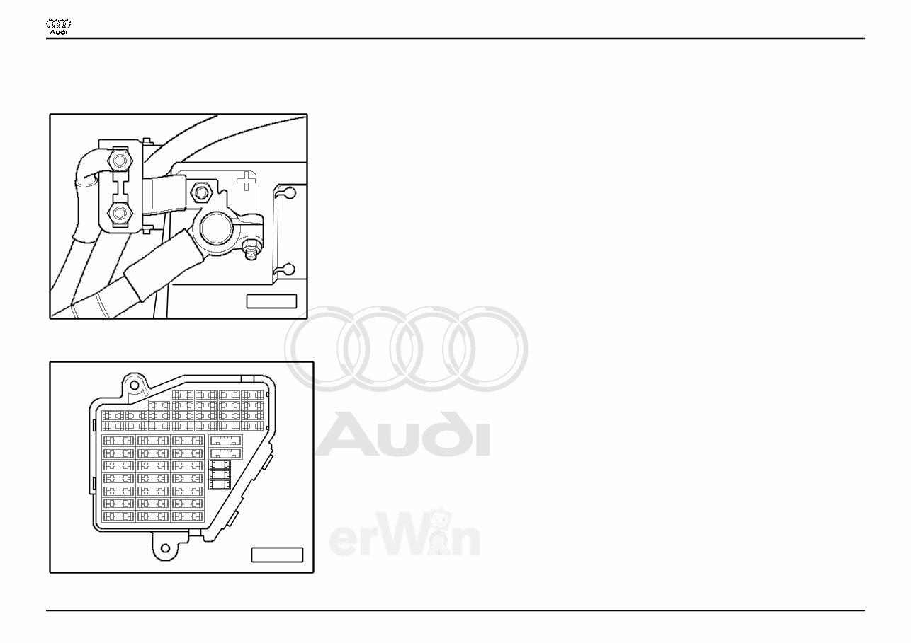
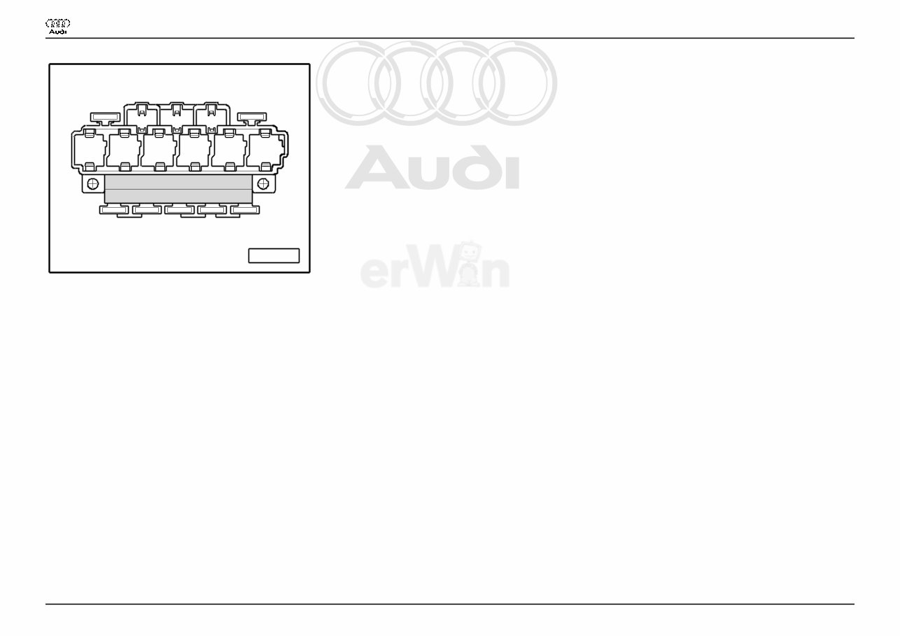
Protected by copyright. Copying for private or commercial purposes, in part or in whole, is not permitted unless authorised by AUDI AG. AUDI AG does not guarantee or accept any liability with respect to the correctness of information in this document. Copyright by AUDI AG. Basic Equipment Lowline From 2003 m. y. Main fuse A97--0220 ♦ on the Battery Fuse holder A97--0242 23 22 21 20 19 18 17 16 15 14 13 12 11 10 9 8 7 6 5 3 4 1 2 44 43 42 41 40 37 39 38 36 35 34 33 32 31 30 29 28 27 26 25 24 Res Res Res Res Res Audi A4 Wiring Diagram No. 3 / 1 12.2005
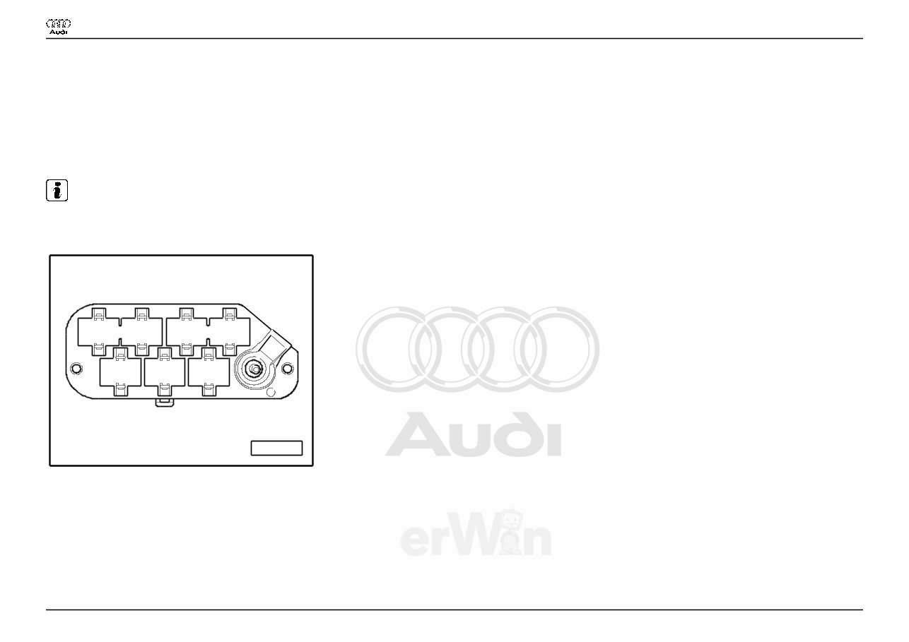
Protected by copyright. Copying for private or commercial purposes, in part or in whole, is not permitted unless authorised by AUDI AG. AUDI AG does not guarantee or accept any liability with respect to the correctness of information in this document. Copyright by AUDI AG. ♦ Instrument panel driver side Fuse Colors 30 A - Green 25 A - Withe 20 A - Yellow 15 A - Blue 10 A - Red 7,5 A - Brown 5 A - Beige Note: ♦ Fuse in fusebox from 23 onwards are numbered 223 onwards in Current Flow Diagram. Coupling station with threaded connection A97--0248 5 6 7 1 2 3 4 ♦ in the electronics box, plenum chamber 1 - 10-Pin Connector, black (T10) 2 - 10-Pin Connector, brown (T10a) 3 - 17-Pin Connector, red (T17d) 6 - 17-Pin Connector, white (T17e) Audi A4 Wiring Diagram No. 3 / 1 12.2005
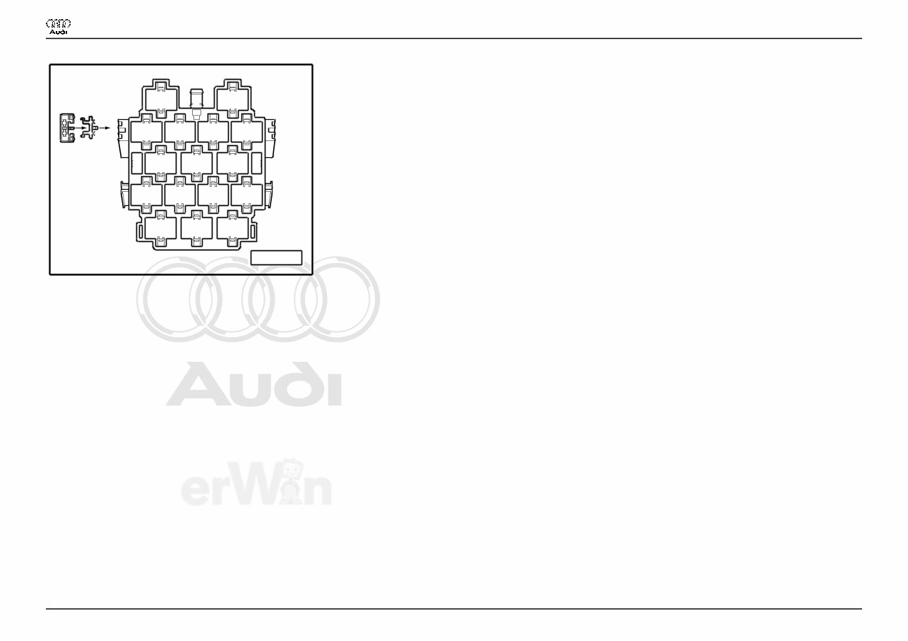
Protected by copyright. Copying for private or commercial purposes, in part or in whole, is not permitted unless authorised by AUDI AG. AUDI AG does not guarantee or accept any liability with respect to the correctness of information in this document. Copyright by AUDI AG. Connector station A-pillar A97--0247 8 11 12 13 14 2 3 4 5 6 7 10 9 16 15 17 A B 1 ♦ behind side trim, left 13 - 10-Pin Connector, violet (T10c) 14 - 10-Pin Connector, grey (T10d) 15 - 17-Pin Connector, green (T17b) 16 - 17-Pin Connector, red (T17a) 17 - 17-Pin Connector, black (T17) Audi A4 Wiring Diagram No. 3 / 1 12.2005
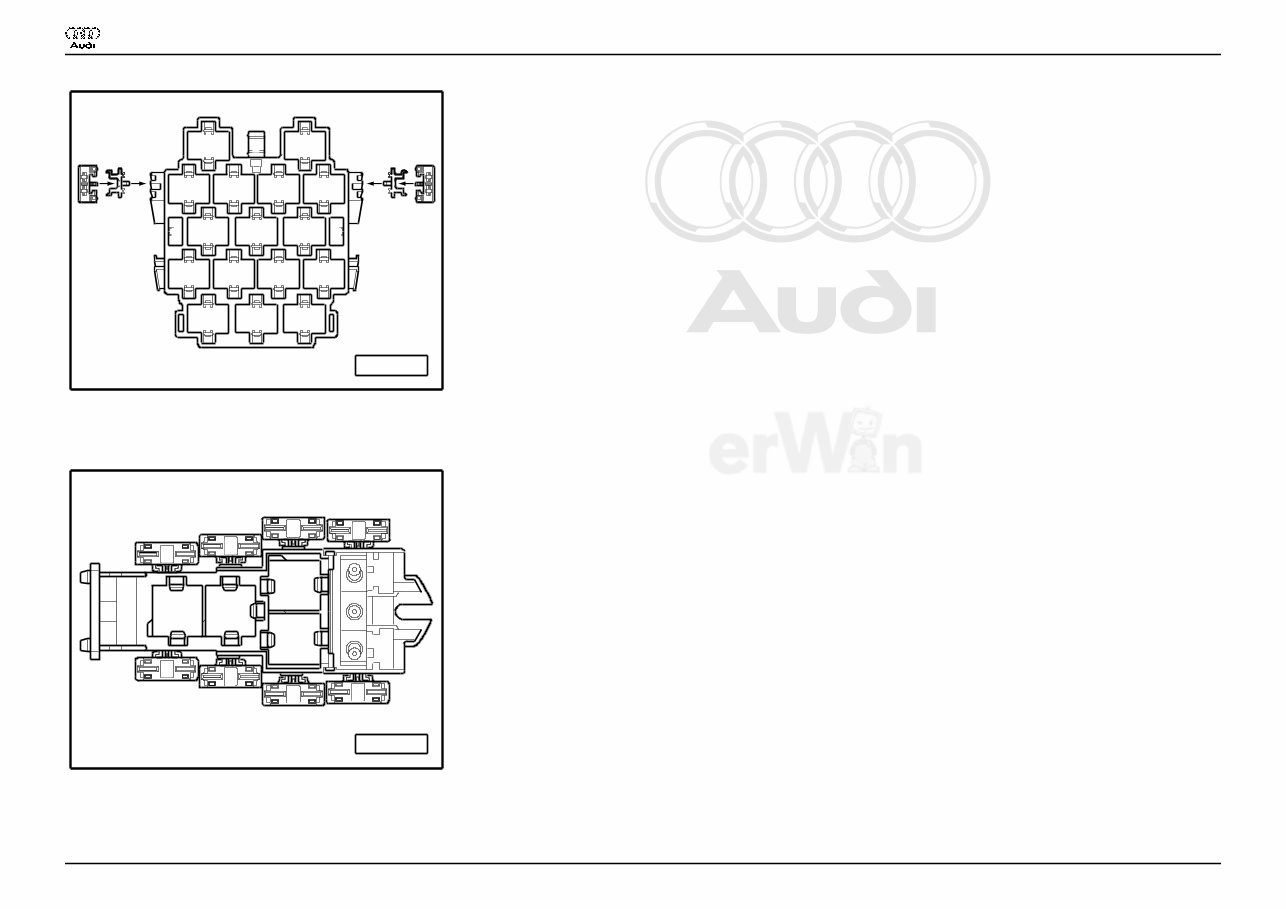
Protected by copyright. Copying for private or commercial purposes, in part or in whole, is not permitted unless authorised by AUDI AG. AUDI AG does not guarantee or accept any liability with respect to the correctness of information in this document. Copyright by AUDI AG. Connector station A-pillar A97--0400 8 11 12 13 14 2 3 4 5 6 7 10 9 16 15 17 A B 1 C E D F ♦ behind side trim, right 15 - 17-Pin Connector, red (T17c) 4-Pin Relay Carrier with threaded connection A97--0245 1 2 3 4 C B G E F A D H ♦ Instrument panel driver side Audi A4 Wiring Diagram No. 3 / 1 12.2005
Protected by copyright. Copying for private or commercial purposes, in part or in whole, is not permitted unless authorised by AUDI AG. AUDI AG does not guarantee or accept any liability with respect to the correctness of information in this document. Copyright by AUDI AG. 9-Pin Relay Carrier with Vehicle Electrical System Control Module A97--0399 8 9 7 A 1 B 2 3 4 5 6 C D E F G ♦ Instrument panel driver side, behind 3-Pin Relay Carrier 3 - Horn Relay (J4) 6 - Load Reduction Relay (J59) Audi A4 Wiring Diagram No. 3 / 1 12.2005
The 2002-2008 Audi A4 Service & Repair Manual is your comprehensive guide to maintaining, repairing, and servicing Audi A4 models from 2002 through 2008. This manual provides detailed step-by-step procedures, clear illustrations, diagrams, and precise specifications designed to simplify even the most complex repair and service tasks.
Perfect for both professional mechanics and dedicated DIY enthusiasts, this manual covers everything from routine maintenance tasks—including oil changes and brake pad replacements—to major repairs such as engine overhauls and transmission rebuilds.
Models Covered:
2002 Audi A4
2003 Audi A4
2004 Audi A4
2005 Audi A4
2006 Audi A4
2007 Audi A4
2008 Audi A4
Whether you are troubleshooting electrical issues, diagnosing engine problems, or replacing worn-out components, this manual provides the expert information and guidance you need to get the job done right. Invest in this all-inclusive Audi A4 Service & Repair Manual to keep your vehicle in peak condition.