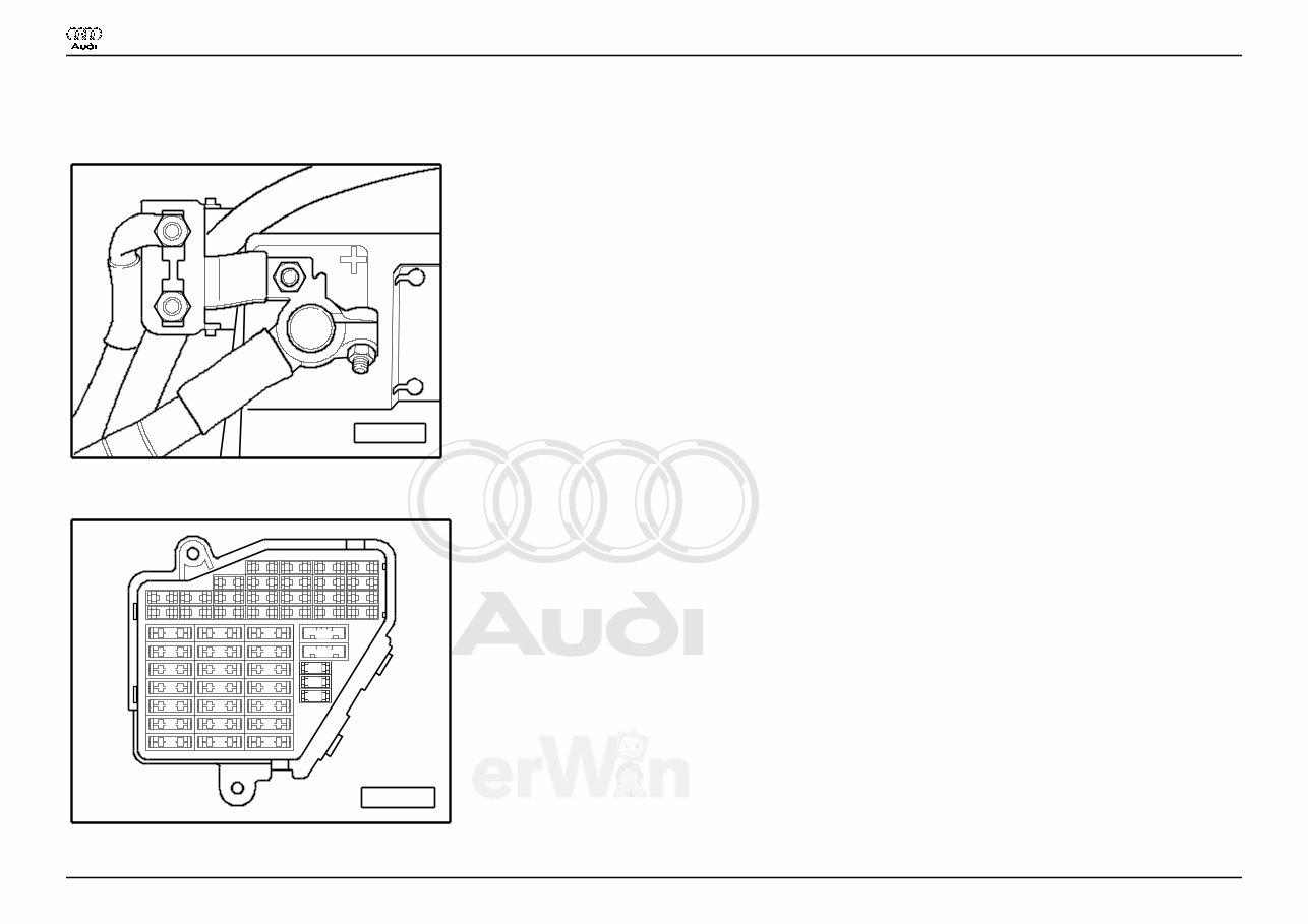
Protected by copyright. Copying for private or commercial purposes, in part or in whole, is not permitted unless authorised by AUDI AG. AUDI AG does not guarantee or accept any liability with respect to the correctness of information in this document. Copyright by AUDI AG. Basic Equipment Lowline From 2003 m. y. Main fuse A97--0220 ♦ on the Battery Fuse holder A97--0242 23 22 21 20 19 18 17 16 15 14 13 12 11 10 9 8 7 6 5 3 4 1 2 44 43 42 41 40 37 39 38 36 35 34 33 32 31 30 29 28 27 26 25 24 Res Res Res Res Res Audi A4 Wiring Diagram No. 3 / 1 12.2005
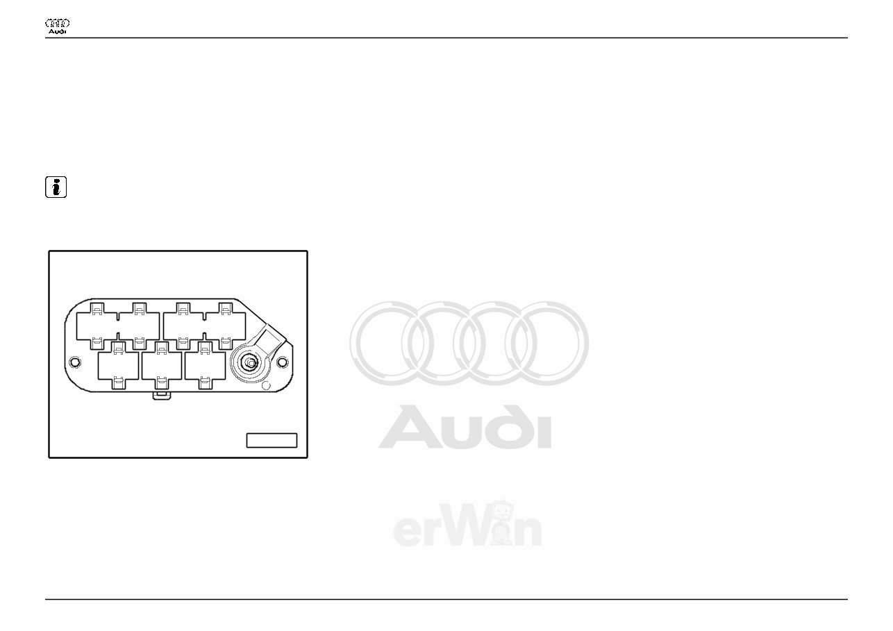
Protected by copyright. Copying for private or commercial purposes, in part or in whole, is not permitted unless authorised by AUDI AG. AUDI AG does not guarantee or accept any liability with respect to the correctness of information in this document. Copyright by AUDI AG. ♦ Instrument panel driver side Fuse Colors 30 A - Green 25 A - Withe 20 A - Yellow 15 A - Blue 10 A - Red 7,5 A - Brown 5 A - Beige Note: ♦ Fuse in fusebox from 23 onwards are numbered 223 onwards in Current Flow Diagram. Coupling station with threaded connection A97--0248 5 6 7 1 2 3 4 ♦ in the electronics box, plenum chamber 1 - 10-Pin Connector, black (T10) 2 - 10-Pin Connector, brown (T10a) 3 - 17-Pin Connector, red (T17d) 6 - 17-Pin Connector, white (T17e) Audi A4 Wiring Diagram No. 3 / 1 12.2005
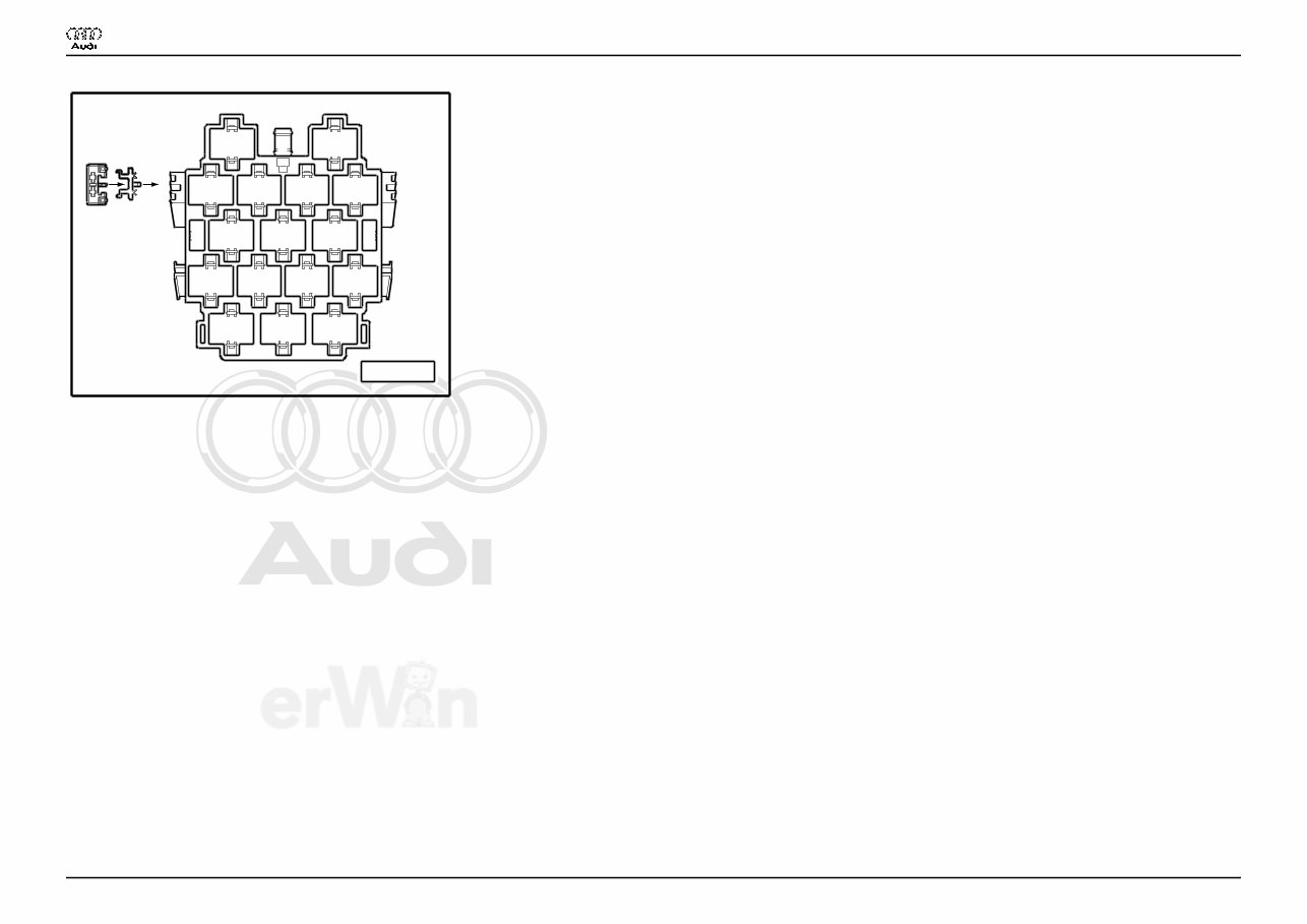
Protected by copyright. Copying for private or commercial purposes, in part or in whole, is not permitted unless authorised by AUDI AG. AUDI AG does not guarantee or accept any liability with respect to the correctness of information in this document. Copyright by AUDI AG. Connector station A-pillar A97--0247 8 11 12 13 14 2 3 4 5 6 7 10 9 16 15 17 A B 1 ♦ behind side trim, left 13 - 10-Pin Connector, violet (T10c) 14 - 10-Pin Connector, grey (T10d) 15 - 17-Pin Connector, green (T17b) 16 - 17-Pin Connector, red (T17a) 17 - 17-Pin Connector, black (T17) Audi A4 Wiring Diagram No. 3 / 1 12.2005
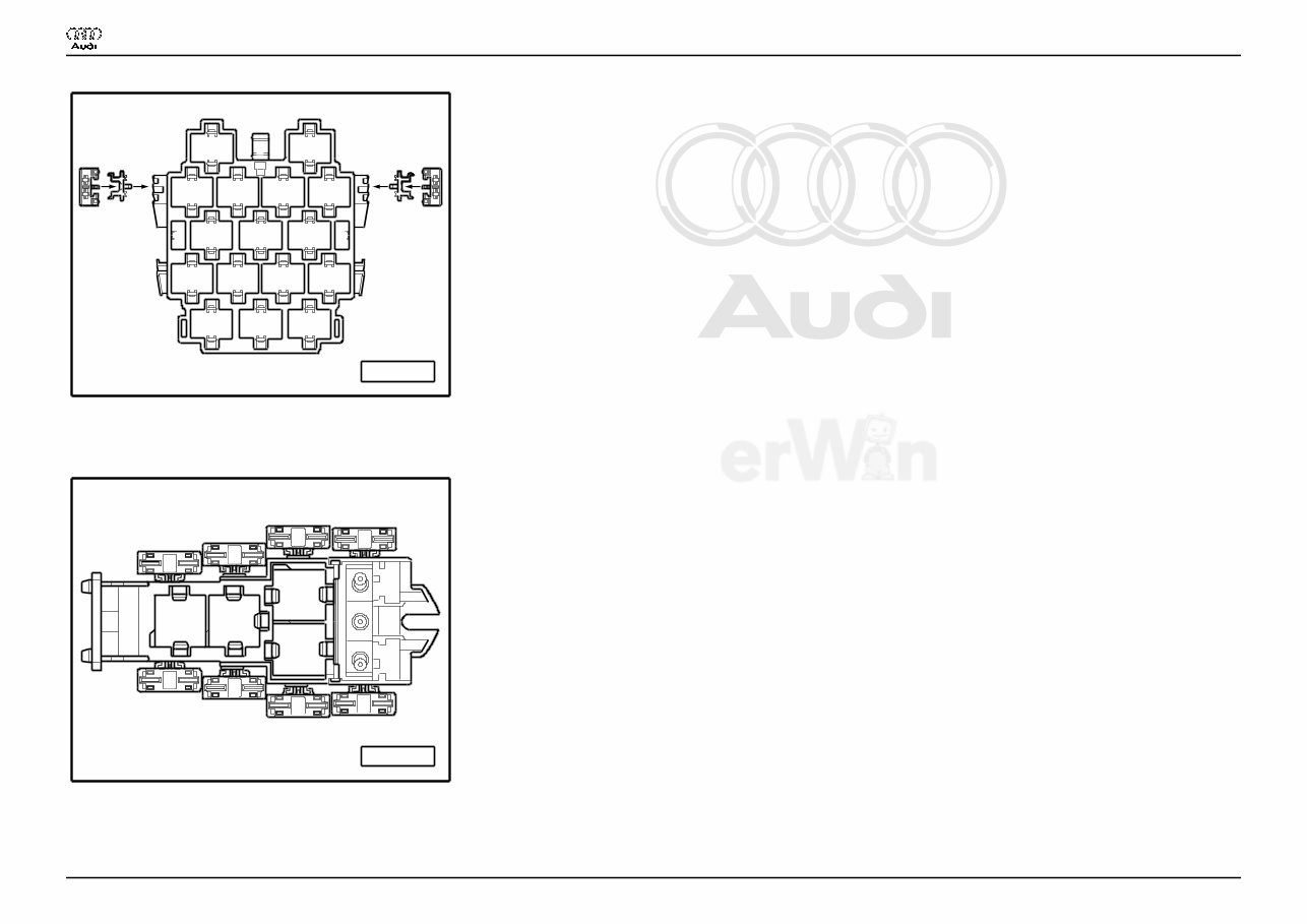
Protected by copyright. Copying for private or commercial purposes, in part or in whole, is not permitted unless authorised by AUDI AG. AUDI AG does not guarantee or accept any liability with respect to the correctness of information in this document. Copyright by AUDI AG. Connector station A-pillar A97--0400 8 11 12 13 14 2 3 4 5 6 7 10 9 16 15 17 A B 1 C E D F ♦ behind side trim, right 15 - 17-Pin Connector, red (T17c) 4-Pin Relay Carrier with threaded connection A97--0245 1 2 3 4 C B G E F A D H ♦ Instrument panel driver side Audi A4 Wiring Diagram No. 3 / 1 12.2005
Protected by copyright. Copying for private or commercial purposes, in part or in whole, is not permitted unless authorised by AUDI AG. AUDI AG does not guarantee or accept any liability with respect to the correctness of information in this document. Copyright by AUDI AG. 9-Pin Relay Carrier with Vehicle Electrical System Control Module A97--0399 8 9 7 A 1 B 2 3 4 5 6 C D E F G ♦ Instrument panel driver side, behind 3-Pin Relay Carrier 3 - Horn Relay (J4) 6 - Load Reduction Relay (J59) Audi A4 Wiring Diagram No. 3 / 1 12.2005
The 2003 Audi A4 (B6) Service & Repair Manual is an indispensable resource for owners and mechanics who want to keep their vehicle in top condition. Whether handling routine maintenance or addressing mechanical issues, this manual provides detailed factory-based procedures to ensure accuracy and reliability.
Designed for both professionals and DIY enthusiasts, it offers step-by-step instructions and technical insights to assist with servicing, troubleshooting, and repairs. From general upkeep to more complex mechanical work, this manual serves as a valuable guide to maintaining your Audi A4’s performance and longevity.
With manufacturer-backed information, this manual is an essential tool for anyone looking to extend the life of their vehicle, prevent costly breakdowns, and perform repairs with confidence.
Printable: Yes Language: English Compatibility: Pretty much any electronic device, incl. PC & Mac computers, Android and Apple smartphones & tablet, etc. Requirements: Adobe Reader (free)