

2015 Audi A3 Service & Repair Manual
What's Included?
Fast Download Speeds
Offline Viewing
Access Contents & Bookmarks
Full Search Facility
Print one or all pages of your manual

Protected by copyright. Copying for private or commercial purposes, in part or in whole, is not
permitted unless authorised by AUDI AG. AUDI AG does not guarantee or accept any liability
with respect to the correctness of information in this document. Copyright by AUDI AG.
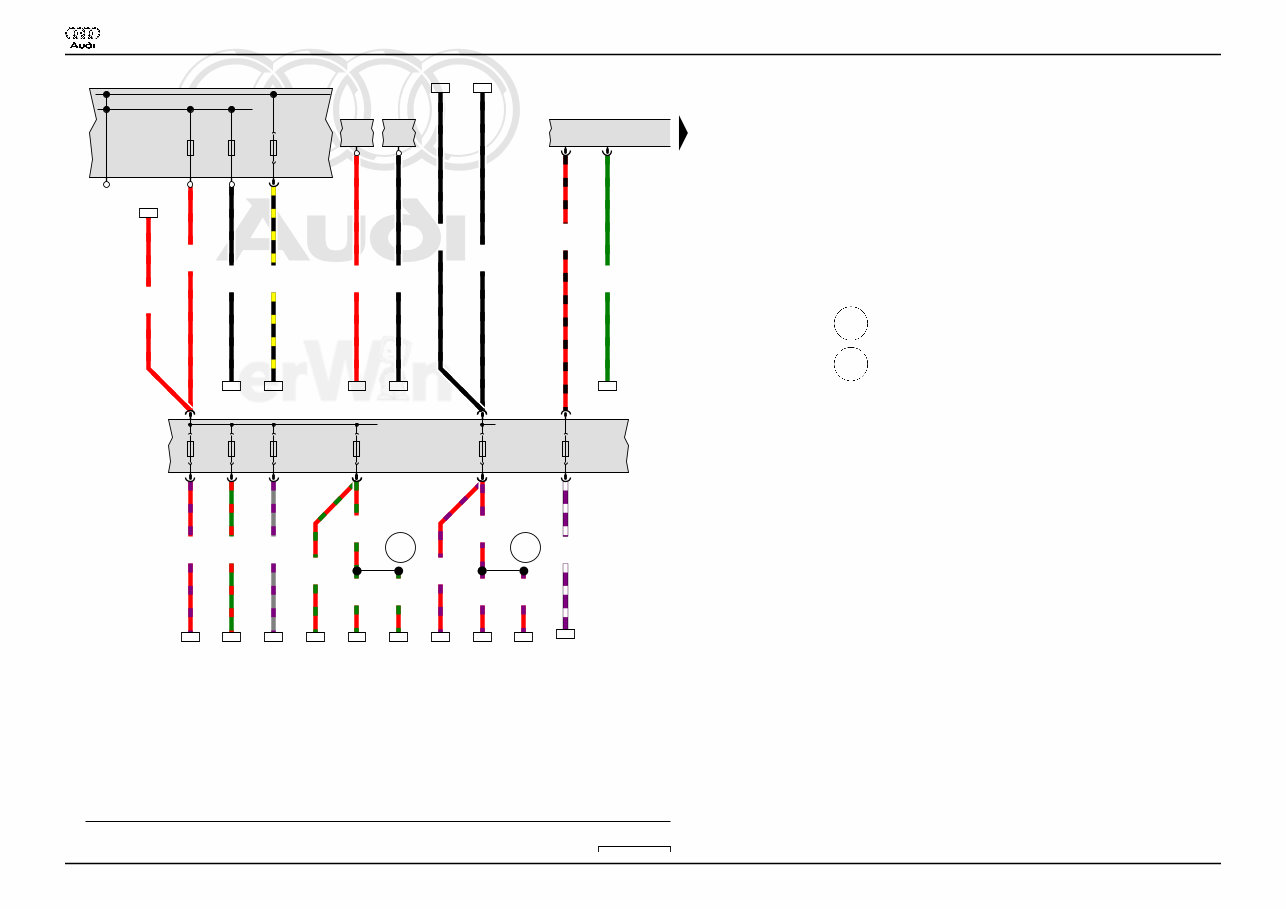
Comfort system, LHD , (L0L)
from March 2012
Audi A3
Wiring Diagram
No. 2 / 1
11.2015
Protected by copyright. Copying for private or commercial purposes, in part or in whole, is not
permitted unless authorised by AUDI AG. AUDI AG does not guarantee or accept any liability
with respect to the correctness of information in this document. Copyright by AUDI AG.
1 2 3 4 5 6 7 8 9 10 11 12 13 14
8V1-002021115
J519
SC
SC29
SB20 SA1
SC42 SC6 SC8 SC25
SA4
SC39
B320 B321
S131 S132
16.0
rt
*
A1
J1A
0.5
rt/sw
T73c
/12
29a
2.5
rt/vi
190
*2
25a
2.5
rt/gn
223
*2
39a
0.5
gn
21
*3
T73c
/9
0.5
sw/ge
91
20a
0.5
vi/ws
38
29
4.0
rt/vi
16
42a
0.35
gn/rt
88
*4
6a
0.75
gr/vi
56
8a
10.0
sw
10.0
sw
10
4
*
*
K2A
A2
2.5
rt/vi
*5
25a
2.5
rt/vi
189
*5
2.5
rt/vi
107
*5
2.5
rt/gn
*5
39a
2.5
rt/gn
222
*5
2.5
rt/gn
121
*5
16.0
rt
16.0
rt
7
2
*6
*6
A1
A1
10.0
sw
10.0
sw
9
8
*6
*6
B1
A2
1B
190 223
21 91
38
16 88 56
10
4
189 107 222 121
7
2 9
8
ws = white
sw = black
ro = red
rt = red
br = brown
gn = green
bl = blue
gr = grey
li = lilac
vi = lilac
ge = yellow
or = orange
rs = pink
Fuse panel C
J519 Vehicle electrical control module system
SA1 Fuse 1 (on fuse panel A)
SA4 Fuse 4 (on fuse panel A)
SC Fuse panel C
SC6 Fuse 6 (on fuse panel C)
SC8 Fuse 8 (on fuse panel C)
SB20 Fuse 20 (on fuse panel B)
SC25 Fuse 25 (on fuse panel C)
SC29 Fuse 29 (on fuse panel C)
SC39 Fuse 39 (on fuse panel C)
SC42 Fuse 42 (on fuse panel C)
S131 Safety fuse 1
S132 Safety fuse 2
T73c 73-pin connector
B320 Positive connection 6 (30a) (in main wiring harness)
B321 Positive connection 7 (30a) (in main wiring harness)
* Not for RS3
*2 Only for vehicles with 3-door equipment
*3 Only for vehicles without automatic headlamp range control
*4 through April 2015
*5 Only for vehicles with 5-door equipment
*6 Only for RS3
Audi A3
Wiring Diagram
No. 2 / 2
11.2015
Protected by copyright. Copying for private or commercial purposes, in part or in whole, is not
permitted unless authorised by AUDI AG. AUDI AG does not guarantee or accept any liability
with respect to the correctness of information in this document. Copyright by AUDI AG.
15 16 17 18 19 20 21 22 23 24 25 26 27 28
8V1-002031115
J519
L229 L231 L230 G304
*
B732
375
57
98 396 397
0.35
gn
T2ma
/2
0.35
gn
T2mb
/2
0.35
gn
T2mc
/2
0.35
br
76
T2ma
/1
0.35
br
T2mb
/1
0.35
br
78
T2mc
/1
0.5
gn
13
*2
1.0
br
72
4.0
rt/vi
3
T73a
/73
0.5
gn
*3
T10a
/9
0.5
gn
*3
T46b
/39
T10a
/9
0.5
br/gn
*4
T73a
/51
T2m
/1
0.5
br/gn
*4
T2m
/1
T2mm
/2
0.5
br
*4
T2mm
/1
1.0
br
*4
1.0
br
*5
*6
1.0
br
*5
*7
0.5
br
*5
*6
T2mm
/1
0.5
br
*5
*7
T2mm
/1
0.5
br/gn
*5
T73a
/51
T2mm
/2
76 78
13
72
3
ws = white
sw = black
ro = red
rt = red
br = brown
gn = green
bl = blue
gr = grey
li = lilac
vi = lilac
ge = yellow
or = orange
rs = pink
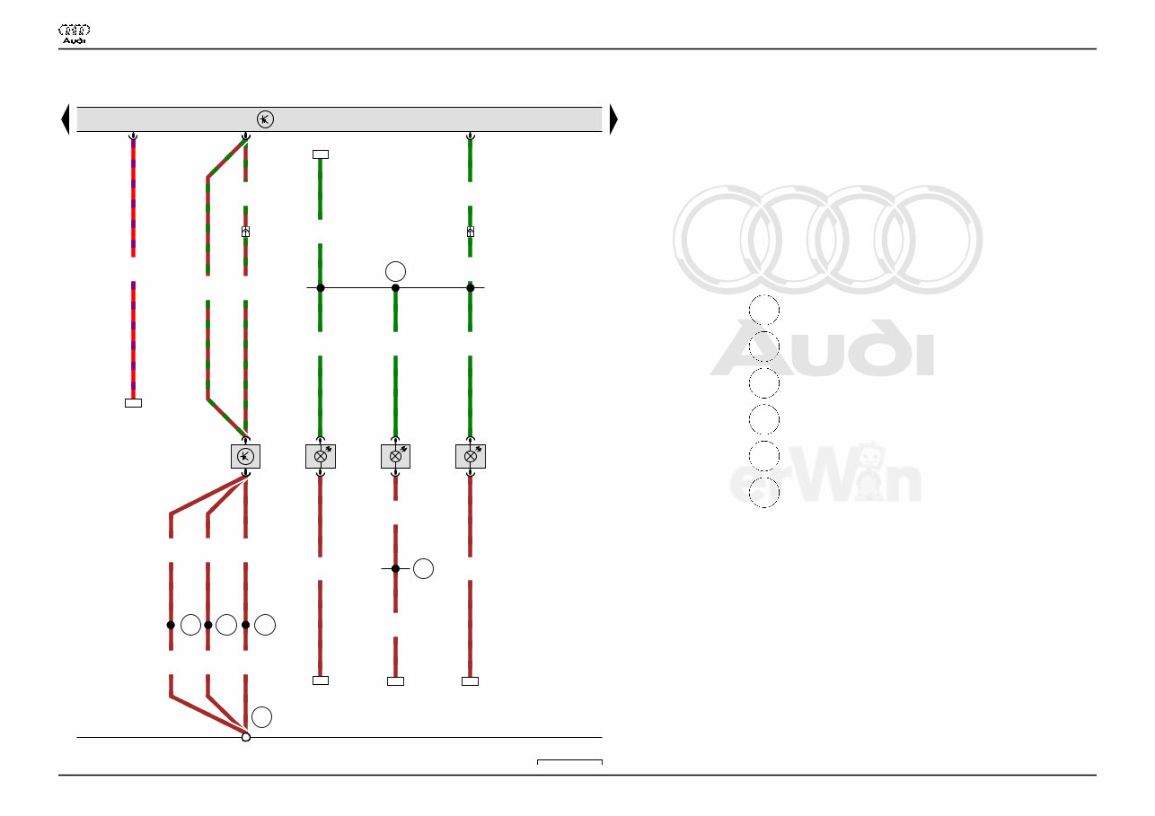
Rear window breakage sensor, Left instrument panel
ambient lighting lamp, Right instrument panel ambient
lighting lamp, Center instrument panel ambient lighting lamp
G304 Rear window breakage sensor
J519 Vehicle electrical control module system
L229 Left instrument panel ambient lighting lamp
L230 Right instrument panel ambient lighting lamp
L231 Center instrument panel ambient lighting lamp
T2m 2-pin connector
T2ma 2-pin connector
T2mb 2-pin connector
T2mc 2-pin connector
T2mm 2-pin connector
T10a 10-pin connector, white
T46b 46-pin connector
T73a 73-pin connector
57 Ground connection on left rear pillar
98 Ground connection (in rear lid wiring harness)
375 Ground connection 10 (in main wiring harness)
396 Ground connection 31 (in main wiring harness)
397 Ground connection 32 (in main wiring harness)
B732 Connection 58s (in main wiring harness) 2
* For vehicles with anti-theft alarm system
*2 Only for vehicles without automatic headlamp range control
*3 Only for vehicles with automatic headlamp range control
*4 Through October 2014
*5 from November 2014
*6 Only for vehicles with 3-door equipment
*7 Only for vehicles with 5-door equipment
Audi A3
Wiring Diagram
No. 2 / 3
11.2015
Protected by copyright. Copying for private or commercial purposes, in part or in whole, is not
permitted unless authorised by AUDI AG. AUDI AG does not guarantee or accept any liability
with respect to the correctness of information in this document. Copyright by AUDI AG.
29 30 31 32 33 34 35 36 37 38 39 40 41 42
8V1-002041115
J519
W14
*
F148
*
B73
L232
368
687
B46
W35
*2
B465
*3
F123
0.35
rt/gr
T2mg
/2
T2me
/2
0.35
gr/ws
T73c
/62
0.35
gr/ws
*4
T2md
/2
0.35
br
T2md
/1
1.5
br
0.35
vi/ws
T2me
/1
0.35
br
79
T2mg
/1
0.35
gr/ws
*5
T2md
/2
T73c
/3
0.5
vi/ws
12
0.35
vi/ws
T2kd
/2
0.5
ws
T73a
/52
0.35
ws
T17f
/14
0.35
ws
T2kd
/1
0.35
ws
T17f
/14
T4cf
/1
0.35
gr/ws
*6
T10a
/10
T2md
/2
0.35
gr/ws
T46b
/2
T10a
/1
0.35
gr/ws
112
0.35
gr/ws
126
79
12
112 126
ws = white
sw = black
ro = red
rt = red
br = brown
gn = green
bl = blue
gr = grey
li = lilac
vi = lilac
ge = yellow
or = orange
rs = pink
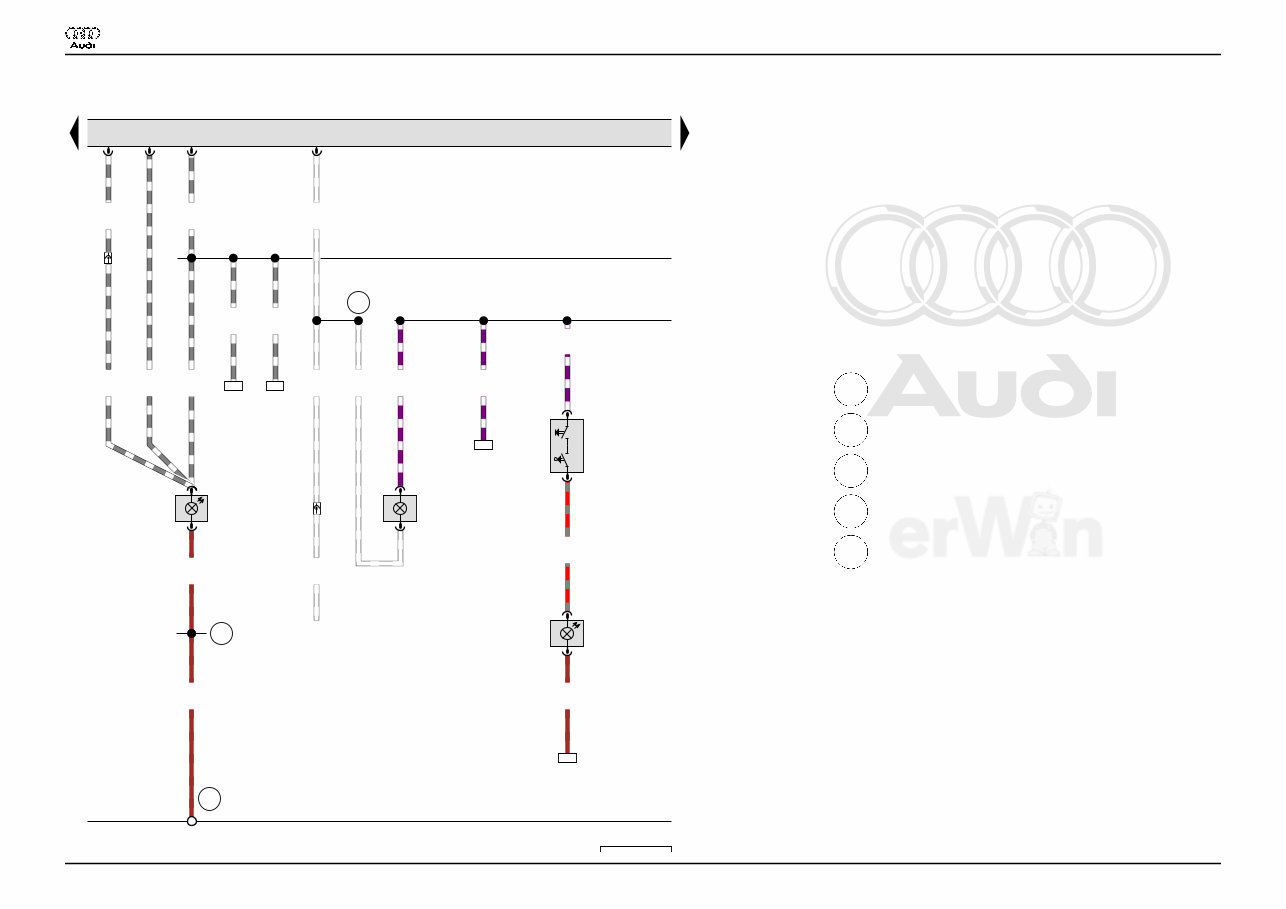
Front passenger vanity mirror lamp contact switch,
Cupholder ambient lighting lamp, Right luggage
compartment lamp
F123 Rear lid alarm switch
F148 Front passenger vanity mirror lamp contact switch
J519 Vehicle electrical control module system
L232 Cupholder ambient lighting lamp
T2kd 2-pin connector
T2md 2-pin connector
T2me 2-pin connector
T2mg 2-pin connector
T4cf 4-pin connector
T10a 10-pin connector, white
T17f 17-pin connector, black
T46b 46-pin connector
T73a 73-pin connector
T73c 73-pin connector
W14 Front passenger vanity mirror lamp
W35 Right luggage compartment lamp
368 Ground connection 3 (in main wiring harness)
687 Ground connection 1 on center tunnel
B465 Connection 1 (in main wiring harness)
B467 Connection 3 (in main wiring harness)
B731 Connection 58s (in main wiring harness) 1
* Only for vehicles with illuminated vanity mirror
*2 Depending on equipment
*3 Through October 2014
*4 Only for vehicles with auxiliary lamps
*5 Only for vehicles with Halogen headlamps
*6 Only for vehicles with Xenon headlamps
Audi A3
Wiring Diagram
No. 2 / 4
11.2015
Protected by copyright. Copying for private or commercial purposes, in part or in whole, is not
permitted unless authorised by AUDI AG. AUDI AG does not guarantee or accept any liability
with respect to the correctness of information in this document. Copyright by AUDI AG.
43 44 45 46 47 48 49 50 51 52 53 54 55 56
8V1-002051115
J519
W20
*
F147
*
WX3
*2
E 0 TK
W43
*2
B731
B731 B73
B316
B467
B467 B46
367
W13 W19
W11 W12 Y7
W1
0.35
vi/ws
T2mf
/1
0.5
br
T2mh
/1
0.35
br
T6d
/3
0.35
vi/ws
T6d
/5
0.35
gr/ws
T6d
/6
0.75
gr/vi
T6d
/1
0.35
gn
66
T6d
/2
0.35
ws/gn
T6ax
/1
T12z
/1
0.35
gr/gn
T6ax
/2
T12z
/2
0.35
br
T6ax
/3
T12z
/3
0.35
ws/vi
T6ax
/4
T12z
/4
0.35
gr/vi
T6ax
/5
T12z
/5
0.5
rt/bl
T6ax
/6
T12z
/12
0.35
bl/rt
T8a
/6
T6d
/4
0.35
rt/gr
T2mf
/2
T2mh
/2
0.75
gr/vi
5
0.35
gn/rt
87
*3
66
5
87
ws = white
sw = black
ro = red
rt = red
br = brown
gn = green
bl = blue
gr = grey
li = lilac
vi = lilac
ge = yellow
or = orange
rs = pink
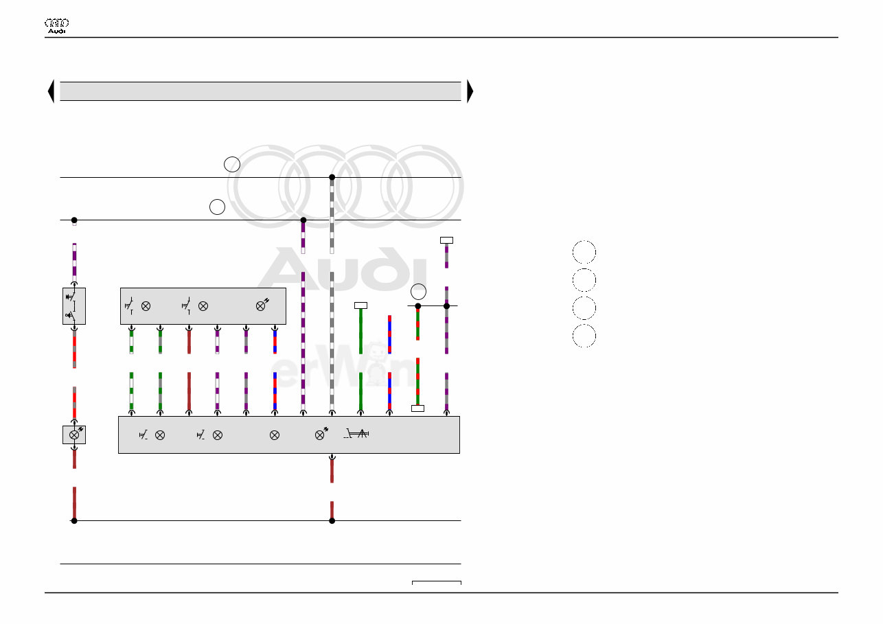
Front roof module, Rear interior lamp
F147 Driver vanity mirror lamp contact switch
J519 Vehicle electrical control module system
T2mf 2-pin connector
T2mh 2-pin connector
T6ax 6-pin connector
T6d 6-pin connector
T8a 8-pin connector
T12z 12-pin connector
W1 Front interior lamp
WX3 Front roof module
W11 Left rear reading lamp
W12 Right rear reading lamp
W13 Front passenger reading lamp
W19 Driver reading lamp
W20 Driver vanity mirror lamp
W43 Rear interior lamp
Y7 Automatic dimming interior rearview mirror
367 Ground connection 2 (in main wiring harness)
B316 Positive connection 2 (30a) (in main wiring harness)
B467 Connection 3 (in main wiring harness)
B731 Connection 58s (in main wiring harness) 1
* Only for vehicles with illuminated vanity mirror
*2 Depending on equipment
*3 from May 2015
Audi A3
Wiring Diagram
No. 2 / 5
11.2015
You're Reading a Preview
What's Included?
Fast Download Speeds
Offline Viewing
Access Contents & Bookmarks
Full Search Facility
Print one or all pages of your manual
$37.99
$49.99
Viewed 92 Times Today


Secure transaction
What's Included?
Fast Download Speeds
Offline Viewing
Access Contents & Bookmarks
Full Search Facility
Print one or all pages of your manual
$37.99
$49.99
The 2015 Audi A3 Service & Repair Manual is an essential resource for anyone who owns this vehicle model. It provides comprehensive information and step-by-step instructions for servicing and repairing the various components of the Audi A3. Whether you are a professional mechanic or a DIY enthusiast, this manual will help you maintain and fix your car with confidence.
Key features of the 2015 Audi A3 Service & Repair Manual include:
- Easy-to-follow instructions for all repair and maintenance tasks
- Detailed diagrams and illustrations to aid understanding
- Exploded views of parts to assist with assembly and disassembly
- Comprehensive specifications and technical data
- Troubleshooting guides to identify and resolve common issues
- Step-by-step procedures for routine maintenance such as oil changes and brake pad replacement
Models covered in this manual:
- 2015 Audi A3 1.8T Premium
- 2015 Audi A3 1.8T Premium Plus
- 2015 Audi A3 2.0T Premium
- 2015 Audi A3 2.0T Premium Plus
- 2015 Audi A3 2.0T Prestige
With the 2015 Audi A3 Service & Repair Manual, you can save money on expensive dealership repairs and have the confidence to tackle maintenance tasks on your own. Get your copy today and take control of your Audi A3's maintenance and repair needs.


