

Yanmar YM135 YM135D YM155 YM155D YM195 YM195D YM240 YM240D YM330 YM330D Tractor Workshop Service Repair Shop Manual
What's Included?
Fast Download Speeds
Online & Offline Access
Access PDF Contents & Bookmarks
Full Search Facility
Print one or all pages of your manual
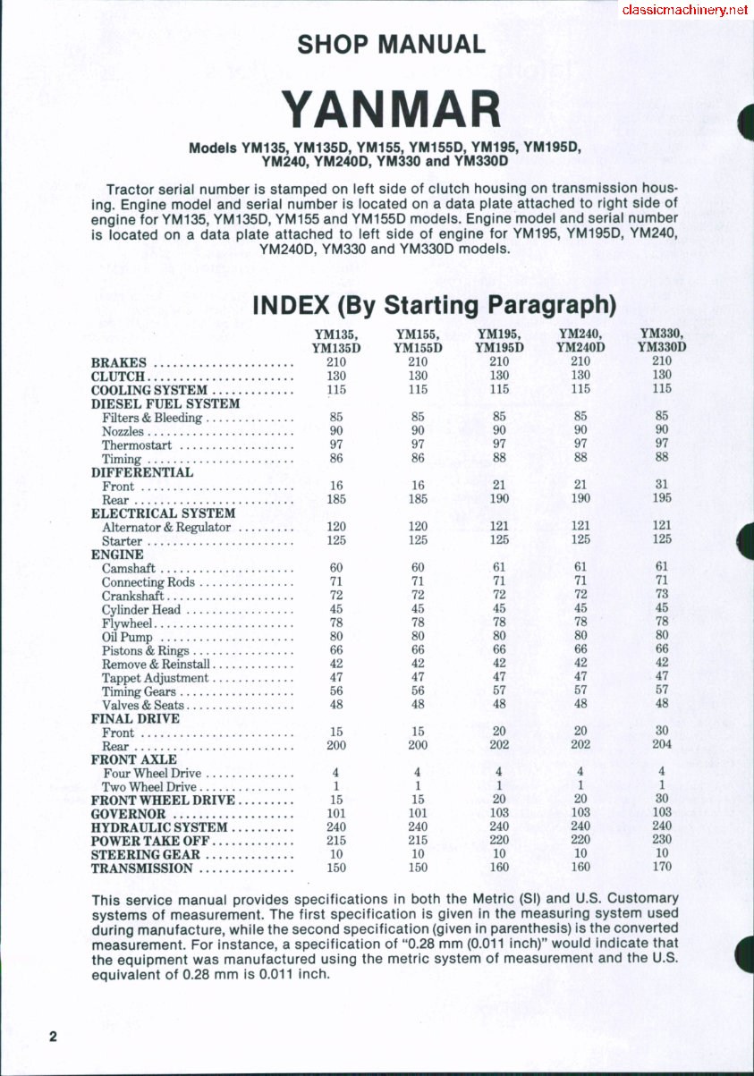
SHOP MANUAL
YANMAR
Models YM135, YM135D, YM155, YM155D, YM195, YM195D,
YM240, YM240D, YM330 and YM330D
Tractor serial number is stamped on left side of clutch housing on transmission hous-
ing. Engine model and serial number is located on a data plate attached to right side of
engine for YM135, YM135D, YM155 and YM155D models. Engine model and serial number
is located on a data plate attached to left side of engine for YM195, YM195D, YM240,
YM240D, YM330 and YM330D models.
i
INDEX (By Starting Paragraph)
YM135,
YM135D
BRAKES 210
CLUTCH 130
COOLING SYSTEM 115
DIESEL FUEL SYSTEM
raters & Bleeding 85
Nozzles 90
Thermostart 97
Timing 86
DIFFERENTIAL
Front 16
Rear 185
ELECTRICAL SYSTEM
Alternator & Regulator 120
Starter 125
ENGINE
Camshaft 60
Connecting Rods 71
Crankshaft 72
Cylinder Head 45
Flywheel 78
Oil Pump 80
Pistons & Rings 66
Remove & Reinstall 42
Tappet Adjustment 47
Timing Gears 56
Valves & Seats 48
FINAL DRIVE
Front 15
Rear 200
FRONT AXLE
Four Wheel Drive 4
Two Wheel Drive 1
FRONT WHEEL DRIVE 15
GOVERNOR 101
HYDRAULIC SYSTEM 240
POWER TAKE OFF 215
STEERING GEAR 10
TRANSMISSION 150
This service manual provides specifications in both the Metric (SI) and U.S. Customary
systems of measurement. The first specification is given in the measuring system used
during manufacture, while the second specification (given in parenthesis) is the converted
measurement. For instance, a specification of "0.28 mm (0.011 inch)" would indicate that
the equipment was manufactured using the metric system of measurement and the U.S.
equivalent of 0.28 mm is 0.011 inch.
YM155,
YM155D
210
130
115
85
90
97
86
16
185
120
125
60
71
72
45
78
80
66
42
47
56
48
15
200
4
1
15
101
240
215
10
150
YM195,
YM195D
210
130
115
85
90
97
88
21
190
121
125
61
71
72
45
78
80
66
42
47
57
48
20
202
4
1
20
103
240
220
10
160
YM240,
YM240D
210
130
115
85
90
97
88
21
190
121
125
61
71
72
45
78
80
66
42
47
57
48
20
202
4
1
20
103
240
220
10
160
YM330,
YM330D
210
130
115
85
90
97
88
31
195
121
125
61
71
73
45
78
80
66
42
47
57
48
30
204
4
1
80
103
240
230
10
170
SHOP MANUAL Paragraphs 1-3
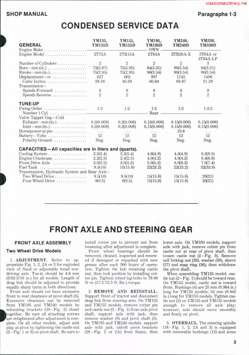
CONDENSED SERVICE DATA
YM135, YM155, YM195, YM240, YM330,
GENERAL YM135D YM155D YM195D YM240D YM330D
Engine Make OWN
Engine Model 2T73A 2TR13A 2T84A 2TR20A-X 3T84A or
3T84A-LP
Number of Cylinders 2 2 2 2 3
Bore-mm (in.) 73(2.87) 75(2.95) 84(3.31) 90(3.54) 84(3.31)
Stroke-mm (in.) 75(2.95) 75(2.95) 90(3.54) 90(3.54) 90(3.54)
Displacement-cc 627 662 997 1145 1496
Cubic Inches 38.26 40.39 60.84 69.87 91.29
Transmission -
Speeds Forward 6 6 8 8 8
Speeds Reverse 2 2 2 2 2
TUNE-UP
FiringOrder 1-2 1-2 1-2 1-2 1-3-2
Number 1 Cyl. Rear
Valve Tappet Gap-Cold
Exhaust-mm (in.) 0.2(0.008) 0.2(0.008) 0.15(0.006) 0.15(0.006) 0.15(0.006)
Inlet-mm (in.) 0.2(0.008) 0.2(0.008) 0.15(0.006) 0.15(0.006) 0.15(0.006)
Horsepower at pto ... ... ... 19.8
Battery-Volts 12 12 12 12 12
Polarity Ground Neg. Neg. Neg. Neg. Neg.
CAPACITIES-All capacities are in liters and (quarts).
Cooling System 3.2(3.4) 3.2(3.4) 4.6(4.9) 4.6(4.9) 6.2(6.5)
Engine Crankcase 2.2(2.3) 2.4(2.5) 4.0(4.2) 4.0(4.2) 6.4(6.8)
Front Drive Axle 3.0(3.2) 3.0(3.2) 5.0(5.3) 6.0(6.3) 7.0(7.4)
Fuel Tank 9.5(10) 15(15.8) 22(23.2) 22(23.2) 32(33.8)
Transmission, Hydraulic System and Rear Axle-
Two Wheel Drive 9.5(10) 9.5(10) 15(15.8) 15(15.8) 20(21)
Four Wheel Drive 9(9.5) 9(9.5) 15(15.8) 15(15.8) 20(21)
FRONT AXLE AND STEERING GEAR
FRONT AXLE ASSEMBLY
Two Wheel Drive Models
1. ADJUSTMENT. Refer to ap-
propriate Fig. 1, 2, 2A or 3 for exploded
view of fixed or adjustable tread non-
driving axle. Toe-in should be 4-8 mm
(5/32-5/16 in.) for all models. Length of
drag link should be adjusted to provide
equally sharp turns in both directions.
Front axle should not have excessive
front to rear clearance at pivot shaft (5).
Excessive clearance can be removed
from YM195 and YM240 models by
relocating brackets (29-Fig. 2) closer
^together. Be sure all attaching screws
Fare retightened after adjustment is com-
plete. On all other models, adjust axle
play at pivot by tightening the castle nut
(2- Fig. 1 or 3) on pivot shaft. Be sure to
install cotter pin to prevent nut from
loosening after adjustment is complete.
Front wheel bearings should be
removed, cleaned, inspected and renew-
ed if damaged or repacked with new
grease after each 300 hours of opera-
tion. Tighten the hub retaining castle
nut, then lock position by installing cot-
ter pin. Tighten wheel lug bolts to 78-98
N-m (57.5-72.3 ft.-lbs.) torque.
2. REMOVE AND REINSTALL.
Support front of tractor and disconnect
drag link from steering arm. On YM135
and YM155 models, remove cotter pin
and castle nut (2 - Fig. 1) from axle pivot
shaft, support axle with jack, then
remove washer (3) and pivot shaft (5).
On YM195 and YM240 models, support
axle with jack, unbolt pivot brackets
(29-Fig. 2 or 2A) from frame, then
lower axle. On YM330 models, support
axle with jack, remove cotter pin from
castle nut at rear of pivot shaft, then
loosen castle nut (2-Fig. 3). Remove
self locking nut (39), washer (38), sleeve
(37) and snap ring (36), then withdraw
the pivot shaft.
When assembling YM135 model, cas-
tle nut (2-Fig. 1) should be toward rear.
On YM155 model, castle nut is toward
front. Bushings (4) are 25 mm (0.984 in.)
long for YM135 models; 24 mm (0.945
in.) long for YM155 models. Tighten cas-
tle nut (2) on YM135 and YM155 models
enough to remove all axle play;
however, axle should move smoothly
and freely on pivot.
3. OVERHAUL. The steering spindle
(18-Fig. 1, 2, 2A and 3) is equipped
with renewable bushings (13) and some
Paragraph 3 Cont.
YANMAR
models are equipped with bearings (15
and 33). Inside diameter of bushings (13)
should be sufficient to provide correct
clearance for the spindle. Adjust spindle
end play by adding covers (11-Fig. 1, 2
or 2A) or shims (40-Fig. 3) as required.
YM135, YM155
Spindle diameter
at bushing 24.948-25.0 mm
(0.9822-0.9843 in.)
Spindle to bushing clearance,
Desired 0.020-0.124 mm
(0.0008-0.0049 in.)
Wear limit 0.4 mm
(0.0157 in.)
Spindle end play,
Desired 0.02-0.086 mm
(0.0008-0.0011 in.)
Wear limit 1.0 mm
(0.0394 in.)
Center pivot pin
diameter 21.947-21.980 mm
(0.8641-0.8654 in.)
Center pivot to bushing clearance.
Desired 0.040-0.123 mm
(0.00157-0.0048 in.)
Wear limit 0.4 mm
(0.0157 in.)
Axle end play on
center pin 0.0-0.5 mm
(0-0.0197 in.)
YM195, YM240
Spindle diameter
at bushing 24.948-25.0 mm
(0.9822-0.9843 in.)
Spindle to bushing clearance.
Desired 0.020-0.122 mm
(0.0008-0.0049 in.)
Wear limit 0.25 mm
(0.0098 in.)
Spindle end play,
Desired 0.02-0.86 mm
(0.0008-0.0011 in.)
Wear limit 1.0 mm
(0.0394 in.)
Center pivot pin
diameter 24.967-25.0 mm
(0.9830-0.9843 in.)
Center pivot to bushing clearance,
Desired 0.020-0.105 mm^
(0.0008-0.0041 in.)
Wear limit 0.4 mm
(0.0157 in.)
Axle end play on center pin,
Desired 0.1-0.3 mm
(0.004-0.011 in.)
Maximum limit 0.5 mm
(0.0197 in.)
YM330
Spindle diameter
at bushing 29.959-29.980 mm
(1.17354.1803 in.)
Spindle to bushing clearance,
Desired 0.020-0.074 mm
(0.0008-0.0029 in.)
Wear limit 0.25 mm
(0.0098 in.)
Spindle end play.
Desired .0.02-0.6 mm
(0.0008-0.0236 in.)
Wear limit 0.7 mm
(0.0276 in.)
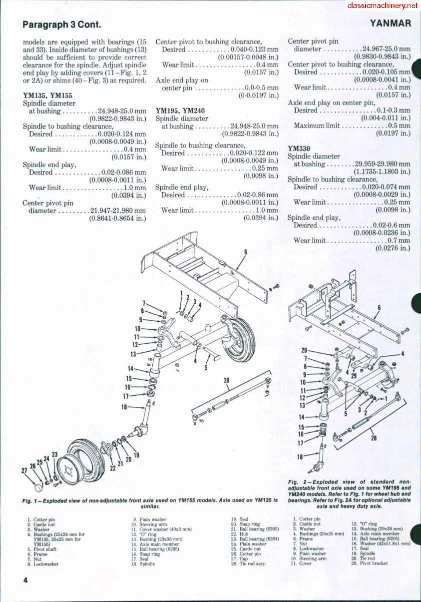
Fig. 1 - Exploded vtew of non-adfustabte front ax/e used on YM155 models. Axle used on YM135 Is
similar.
Fig. 2—Exploded view of standard non-
adiustable front axle used on some YM195 and
YM240 models. Refer to Fig. 1 for wbeel bub and
bearings. Refer to Fig. 2A for optional adjustable
axle and beavy duty axle.
1. Cotter pin
2. Castle nut
3. Washer
4. Bushings (25x24 mm for
YM135, 25x25 mm for
YM155)
5. Pivot shaft
6. Frame
7. Nut
8. Lockwasher
9. Plain washer
10. Steering arm
11. Cover washer (40x3 mm)
12. "0" ring
13. Bushing (29x38 mm)
14. Axle main member
15. Ball bearing (6205)
16. Snap ring
17. Seal
18. Spindle
19. Seal
20. Snap ring
21. Ball bearing (6205)
22. Hub
23. Ball bearing (6204)
24. Plain washer
25. Castle nut
26. Cotter pin
27. Cap
28. Tie rod assy.
1. Cotter pin
2. Castle nut
3. Washer
4. Bushings (25x25 mm)
6. Frame
7. Nut
8. Lockwasher
9. Plain washer
10. Steering wrm
11. Cover
12. "O" ring
13. Bushing (29x38 mm)
14. Axle main member 1
15. Ball bearing (6205)
16. Washer (42x51.8x1 mm)
17. Seal
18. Spindle
28. Tie rod
29. Pivot bracket
SHOP MANUAL
Paragraphs 4-11
Center pivot pin
diameter 34.95-34.975 mm
(1.3760-1.3770 in.)
^Center pivot to bushing clearance.
Desired 0.025-0.089 mm
(0.0010-0.0035 in.)
Wear limit 0.4 mm
(0.0157 in.)
Axle end play on center pin.
Desired 0.1-0.3 mm
(0.0039-0.0118 in.)
Maximum limit 0.5 mm
(0.0197 in.)
Four Wheel Drive
4. ADJUSTMENT. Refer to ap-
propriate paragraphs 15 through 31 for
service to individual units. Toe-in should
be 4-8 mm for all models.
5. REMOVE AND REINSTALL. To
remove the front axle from four wheel
drive models, first block rear wheels.
Loosen the drive shaft cover clamps,
remove retaining screws, then move
drive shaft cover out of the way. Detach
drive shaft from front axle drive pinion.
On all models except YM135D and
YM155D models, be careful not to lose
the steel balls from drive shaft collars.
On all models, detach drag link from
steering arm. Support weight of tractor
by attaching overhead hoist to front
weight support, then remove both front
wheels. Place a jack under center of
front axle to support axle securely when
attaching screws are removed.
On all models, except YM330D,
remove castle nut from axle pivot, then
withdraw pivot shaft. Be careful to pre-
vent axle from falling when pivot is
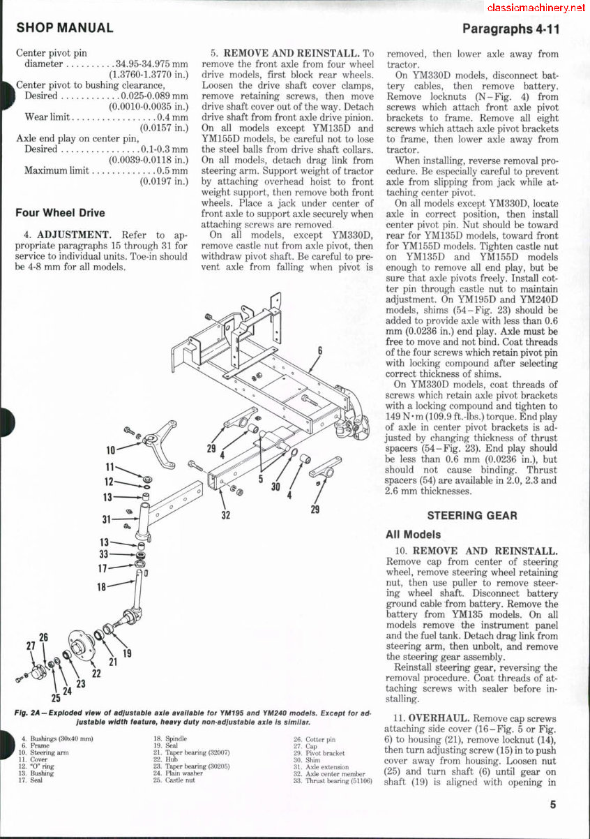
Fig, 2A-Exploded vfew of adfustabtB axle awalfable for YMIBS and YfAZAO models. Except for ad-
lustable width feature, heavy duty non-adjustable axle is similar.
26. Cotter pin
27. Cap
29. Pivot bracket
30. Shim
31. Axle extension
32. Axle center member
33. Thrust bearing (51106)
4. Bushings (30x40 mm)
6. Frame
10. Steering arm
11. Cover
12. "0" ring
13. Bushing
17. Seal
18. Spindle
19. Seal
21. Taper bearing (32007)
22. Hub
23. Taper bearing (30205)
24. Plain washer
25. Castle nut
removed, then lower axle away from
tractor.
On YM330D models, disconnect bat-
tery cables, then remove battery.
Remove locknuts (N-Fig. 4) from
screws which attach front axle pivot
brackets to frame. Remove all eight
screws which attach axle pivot brackets
to frame, then lower axle away from
tractor.
When installing, reverse removal pro-
cedure. Be especially careful to prevent
axle from slipping from jack while at-
taching center pivot.
On all models except YM330D, locate
axle in correct position, then install
center pivot pin. Nut should be toward
rear for YM135D models, toward front
for YM155D models. Tighten castle nut
on YM135D and YM155D models
enough to remove all end play, but be
sure that axle pivots freely. Install cot-
ter pin through castle nut to maintain
adjustment. On YM195D and YM240D
models, shims (54-Fig. 23) should be
added to provide axle with less than 0.6
mm (0.0236 in.) end play. Axle must be
free to move and not bind. Coat threads
of the four screws which retain pivot pin
with locking compound after selecting
correct thickness of shims.
On YM330D models, coat threads of
screws which retain axle pivot brackets
with a locking compound and tighten to
149 N-m (109.9 ft.-lbs.) torque. End play
of axle in center pivot brackets is ad-
justed by changing thickness of thrust
spacers (54-Fig. 23). End play should
be less than 0.6 mm (0.0236 in.), but
should not cause binding. Thrust
spacers (54) are available in 2.0, 2.3 and
2.6 mm thicknesses.
STEERiNG GEAR
All Models
10. REMOVE AND REINSTALL.
Remove cap from center of steering
wheel, remove steering wheel retaining
nut, then use puller to remove steer-
ing wheel shaft. Disconnect battery
ground cable from battery. Remove the
battery from YM135 models. On all
models remove the instrument panel
and the fuel tank. Detach drag link from
steering arm, then unbolt, and remove
the steering gear assembly.
Reinstall steering gear, reversing the
removal procedure. Coat threads of at-
taching screws with sealer before in-
stalling.
11. OVERHAUL. Remove cap screws
attaching side cover (16-Fig. 5 or Fig.
6) to housing (21), remove locknut (14),
then turn adjusting screw (15) in to push
cover away from housing. Loosen nut
(25) and turn shaft (6) until gear on
shaft (19) is aligned with opening in
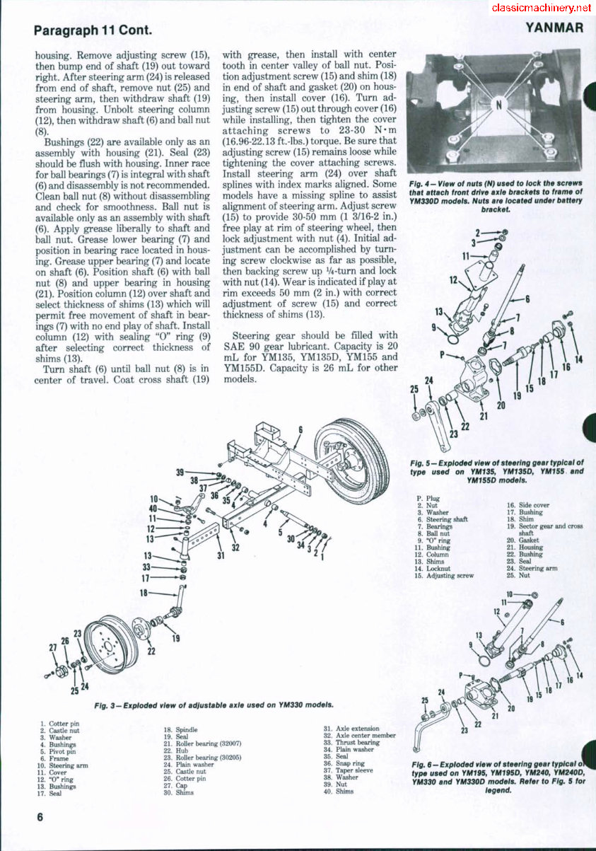
Paragraph 11 Cont.
YANMAR
housing. Remove adjusting screw (15),
then bump end of shaft (19) out toward
right. After steering arm (24) is released
from end of shaft, remove nut (25) and
steering arm, then withdraw shaft (19)
from housing. Unbolt steering column
(12), then withdraw shaft (6) and ball nut
(8).
Bushings (22) are available only as an
assembly with housing (21). Seal (23)
should be flush with housing. Inner race
for ball bearings (7) is integral with shaft
(6) and disassembly is not recommended.
Clean ball nut (8) without disassembling
and check for smoothness. Ball nut is
available only as an assembly with shaft
(6). Apply grease liberally to shaft and
ball nut. Grease lower bearing (7) and
position in bearing race located in hous-
ing. Grease upper bearing (7) and locate
on shaft (6). Position shaft (6) with ball
nut (8) and upper bearing in housing
(21). Position column (12) over shaft and
select thickness of shims (13) which will
permit free movement of shaft in bear-
ings (7) with no end play of shaft. Install
column (12) with sealing "0" ring (9)
after selecting correct thickness of
shims (13).
Turn shaft (6) until ball nut (8) is in
center of travel. Coat cross shaft (19)
with grease, then install with center
tooth in center valley of ball nut. Posi-
tion adjustment screw (15) and shim (18)
in end of shaft and gasket (20) on hous-
ing, then install cover (16). Turn ad-
justing screw (15) out through cover (16)
while installing, then tighten the cover
attaching screws to 23-30 N-m
(16.96-22.13 ft.-lbs.) torque. Be sure that
adjusting screw (15) remains loose while
tightening the cover attaching screws.
Install steering arm (24) over shaft
splines with index marks aligned. Some
models have a missing spline to assist
alignment of steering arm. Adjust screw
(15) to provide 30-50 mm (1 3/16-2 in.)
free play at rim of steering wheel, then
lock adjustment with nut (4). Initial ad-
justment can be accomplished by turn-
ing screw clockwise as far as possible,
then backing screw up V4-turn and lock
with nut (14). Wear is indicated if play at
rim exceeds 50 mm (2 in.) with correct
adjustment of screw (15) and correct
thickness of shims (13).
Steering gear should be filled with
SAE 90 gear lubricant. Capacity is 20
mL for YM135, YM135D, YM155 and
YM155D. Capacity is 26 mL for other
models.
Fig. $- Exploded view of adfustable axle used on rM330 models.
1. Cotter pin
2. Castle nut
3. Washer
4. Bushings
5. Pivot pin
6. Frame
10. Steering arm
11. Cover
12. "0" ring
13. Bushings
17. Seal
18. Spindle
19. Seal
21. RoUer bearing (32007)
22. Hub
23. Roller bearing (30205)
24. Plain washer
25. Castle nut
26. Cotter pin
27. Cap
30. Shims
31. Axle extension
32. Axle center member
33. Thrust bearing
34. Plain washer
35. Seal
36. Snap ring
37. Taper sleeve
38. Washer
39. Nut
40. Shims
Fig. 4 "View of nuts {Hi used to iock tbe screws
tbat attacb front drive axle brackets to frame of
yM330O modeis. Nuts are located under battery
bracket
Fig. 5 — Expioded view of steering gear typlcai of
type used on YM135, YM135D, rM155 and
YM155D models.
P. Plug
2. Nut
3. Washer
6. Steering shaft
7. Bearings
8. Ball nut
9. "0" ring
11. Bushing
12. Column
13. Shims
14. Locknut
15. Adjusting screw
16. Side cover
17. Bushing
18. Shim
19. Sector gear and cross
shaft
20. Gasket
21. Housing
22. Bushing
23. Seal
24. Steering arm
25. Nut
10 ^
25
Fig. 6—Exploded view of steering gear typical ol
type used on YM195, YM195D, YM240, YM240D,
YM330 and YM330D modeis. Refer to Fig. 5 for
iegend.
SHOP MANUAL
FRONT WHEEL
DRIVE
OUTER DRIVE HOUSING
YM135D and YM155D Models
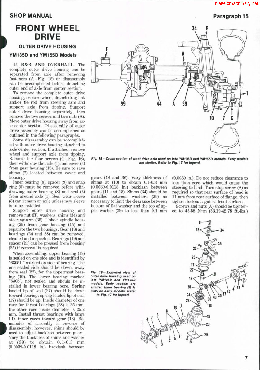
15. R&R AND OVERHAUL. The
complete outer drive housing can be
separated from axle after removing
fasteners (A-Fig, 15) or disassembly
can be accomplished before detaching
outer end of axle from center section.
To remove the complete outer drive
housing, remove wheel, detach drag link
and/or tie rod from steering arm and
support axle from tipping. Support
outer drive housing separately, then
remove the two screws and two nuts (A).
Move outer drive housing away from ax-
le center section. Disassembly of outer
drive assembly can be accomplished as
outlined in the following paragraphs.
Some disassembly can be accomplish-
ed with outer drive housing attached to
axle center section. If attached, remove
wheel and support axle from tipping.
Remove the four screws (C-Fig. 16),
then withdraw the axle (1) and cover (4)
from gear housing (15). Be sure to save
shims (7) located between cover and
housing.
Inner bearing (8), spacer (9) and snap
ring (5) must be removed before with-
drawing outer bearing (8) and seal (6)
from around axle (1). Seal wear sleeve
(3) can remain on axle unless new sleeve
is to be installed.
Support outer drive housing and
remove nut (B), washers, shims (34) and
steering arm (35). Unbolt spindle hous-
ing (25) from gear housing (15) and
separate the two housings. Gear (18) and
bearings (24 and 28) can be removed,
cleaned and inspected. Bearings (19) and
spacer (21) can be pressed from housing
(25) if removal is required.
When assembling, upper bearing (19)
is sealed on one side and is identified by
"6305U" marked on side of bearing. The
one sealed side should be down, away
from seal (27), for the uppermost bear-
ing: (19). The lower bearing marked
"6305", not sealed and should be in-
stalled in lower bearing bore. Spring
loaded lip of seal (27) should be down
toward bearing; spring loaded lip of seal
(17) should be up. Inside diameter of one
race for thrust bearings (28) is 25 mm,
the other race inside diameter is 25.2
mm. Install thrust bearings with large
I.D. inner races toward gear (18). Re-
mainder of assembly is reverse of
disassembly; however, shims should be
used to adjust backlash between gears.
Vary the thickness of shims and washer
at (89) to obtain 0.1-0.3 mm
(0.0039-0.0118 in.) backlash between
Paragraph 15
99
Fig, 15-Crosss0ctlon of front drive axie used on late rMY35D and YM1SSD models. Early models
are similar. Refer to Fig, 17 tor legend.
gears (18 and 36). Vary thickness of
shims at (10) to obtain 0.1-0.3 mm
(0.0039-0.0118 in.) backlash between
gears (11 and 18). Shims (34) should be
installed between washers (29) as
necessary to limit the clearance between
bottom of flat washer and the top of up-
per washer (29) to less than 0.1 mm
(0.0039 in.). Do not reduce clearance to
less than zero which would cause the
steering to bind. Turn stop screw (S) as
required so that rear surface of head is
11 mm from rear surface of flange, then
tighten locknut against front surface.
Screws and nuts (A) should be tighten-
ed to 45-58 N-m (33.19-42.78 ft.-lbs.)
Fig. 16—Exploded view of
outer drive housing used on
late YM135D and YMiSSD
models. Early models are
similar, inner bearing (8) Is
S305 on early models. Refer
to Fig. 17 for legend.
Paragraph 16 YANMAR
torque. Screws (C) should be tightened
to 12-16 N-m (106-142 ft.-lbs.) torque.
Screws attaching spindle (26) to gear
housing (15) should be tightened to 45-58
N-m (33.19-42.78 ft.-lbs.) torque. Wheel
retaining lug bolts should be tightened
to 79-97 N-m (58.27-71.54 ft.-lbs.) tor-
que. The front axle should contain 3
liters (3.2 quarts) of gear lubricant.
DIFFERENTIAL
AND BEVEL GEARS
YM135D and YM155D Models
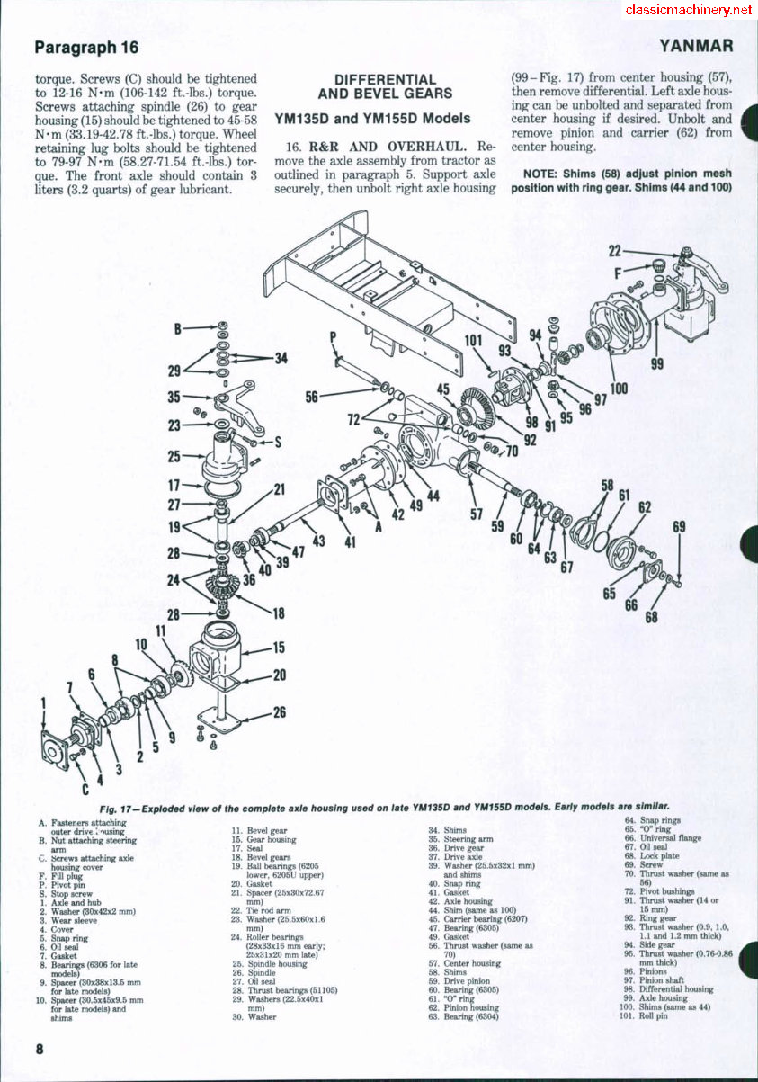
16. R&R AND OVERHAUL. Re-
move the axle assembly from tractor as
outlined in paragraph 5. Support axle
securely, then unbolt right axle housing
(99-Fig. 17) from center housing (57),
then remove differential. Left axle hous-
ing can be unbolted and separated from
center housing if desired. Unbolt and
remove pinion and carrier (62) from
center housing.
NOTE: Shims (58) adjust pinion mesh
position with ring gear. Shims (44 and 100)
Fig. IT—Exptaded ¥i0w of the complete axle housing used on late
YM1350 and YMiSSD models. Early models are similar.
10.
Fasteners attaching
outer drive I 'msing
Nut attaching steering
arm
tScrews attaching axle
housing cover
Fill plug
Pivot pin
Stop screw
Axle and hub
Washer (30x42x2 mnn)
Wear sleeve
Cover
Snap ring
Oil seal
Gasket
Bearings (6306 for late
models)
Spacer (30x38x13.5 nun
for late models)
Spacer (30.5x45x9.5 mm
for late models) and
shims
11. Bevel gear
15. Gear housing
17. Seal
18. Bevel gears
19. Ball bearing (6205
lower, 6205U upper)
20. Gasket
21. Spacer (25x30x72.67
mm)
22. Tie rod arm
23. Washer (25.5x60x1.6
mm)
24. Roller bearings
(28x33x16 mm early;
25x31x20 mni late)
25. Spindle housing
26. Spindle
27. Oil seal
28. Thrust bearings (51105)
29. Washers (22.5x40x1
mm)
30. Washer
34. Shims
35. Steering arm
36. Drive gear
37. Drive axle
39. Washer (25.5x32x1 mm)
and shims
40. Snap ring
41. Gasket
42. Axle housing
44. Shim (same as 100)
45. Carrier bearing (6207)
47. Bearing (6305)
49. Gasket
56. Thrust washer (same as
70)
57. Center housing
58. Shims
59. Drive pinion
60. Bearing (6305)
61. "O"ring
62. Pinion housing
63. Bearing (6304)
64. Snap rings
65. "0" ring
66. Universal flange
67. OU seal
68. Lock plate
69. Screw
70. Thrust washer (same as
56)
72. Pivot bushings
91. Thrust washer (14 or
15 mm)
92. Ring gear
93. Thrust washer (0.9, 1.0,
1.1 and 1.2 mm thick)
94. Side gear
95. Thrust washer (0.76-0.86
mm thick)
96. Pinions
97. Pinion shaft
98. Differential housing
99. Axle housing
100. Shims (same as 44)
101. Roll pin
8
SHOP MANUAL
Paragraph 20
adjust carrier bearings (45). Moving shims
(44 and 100) from one side to the other
moves the differentiai and therefore ad-
justs bevei gear backiash. Be carefui not
to iose or damage shims when dis-
assembiing.
The pinion bearings (60 and 63), car-
rier (62) and related parts can be
assembled on the pinion shaft (59) before
assembling into center housing. The
mesh position can be checked using a
mandrel manufactured to the dimen-
sions shown in Fig. 18. Distance (A)
should be 15.95-16.05 mm (0.6280-
0.6319 in.) if checked with mandrel. If
mandrel is not available and thickness of
shims (58-Fig. 17) is not correct, mesh
position can be checked by coating teeth
of ring gear with mechanics blueing,
then installing differential in center
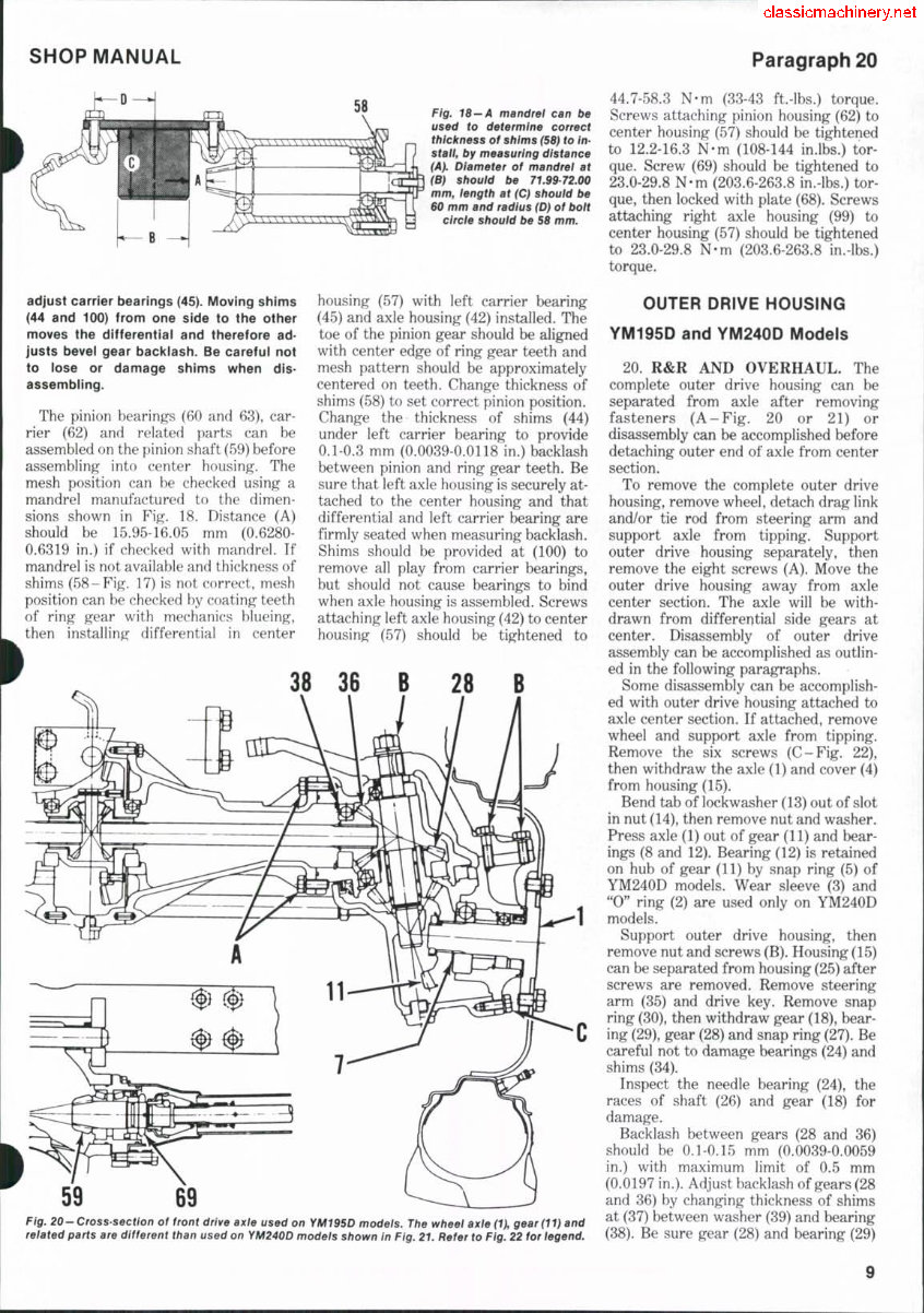
Fig. 18—A mandrel can be
used to determine correct
t/ifc/rness of sbims (58) to In-
staii, by measuring distance
iA}. Diameter of mandrei at
(B) sbouid be 71.9972.00
mm, length at (C) sliouid be
60 mm and radius (D) of boit
cirde sbouid be 58 mm.
housing (57) with left carrier bearing
(45) and axle housing (42) installed. The
toe of the pinion gear should be aligned
with center edge of ring gear teeth and
mesh pattern should be approximately
centered on teeth. Change thickness of
shims (58) to set correct pinion position.
Change the thickness of shims (44)
under left carrier bearing to provide
0.1-0.3 mm (0.0039-0.0118 in.) backlash
between pinion and ring gear teeth. Be
sure that left axle housing is securely at-
tached to the center housing and that
differential and left carrier bearing are
firmly seated when measuring backlash.
Shims should be provided at (100) to
remove all play from carrier bearings,
but should not cause bearings to bind
when axle housing is assembled. Screws
attaching left axle housing (42) to center
housing (57) should be tightened to
38 36 B 28 B
59
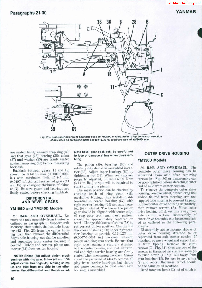
Fig. 20 - Cross section of front drive axle used on YM195D modeis. The wheei dxle (U S^^r (11) and
related parts are different than used on YM240D models shovi/n in Fig. 21. Refer to Fig. 22 for legend.
44.7-58.3 N-m (33-43 ft.-lbs.) torque.
Screws attaching pinion housing (62) to
center housing (57) should be tightened
to 12.2-16.3 N-m (108-144 in.lbs.) tor-
que. Screw (69) should be tightened to
23.0-29.8 N-m (203.6-263.8 in.-lbs.) tor-
que, then locked with plate (68). Screws
attaching right axle housing (99) to
center housing (57) should be tightened
to 23.0-29.8 N-m (203.6-263.8 in.-lbs.)
torque.
OUTER DRIVE HOUSING
YM195D and YM240D Models
20. R&R AND OVERHAUL. The
complete outer drive housing can be
separated from axle after removing
fasteners (A-Fig. 20 or 21) or
disassembly can be accomplished before
detaching outer end of axle from center
section.
To remove the complete outer drive
housing, remove wheel, detach drag link
and/or tie rod from steering arm and
support axle from tipping. Support
outer drive housing separately, then
remove the eight screws (A). Move the
outer drive housing away from axle
center section. The axle will be with-
drawn from differential side gears at
center. Disassembly of outer drive
assembly can be accomplished as outlin-
ed in the following paragraphs.
Some disassembly can be accomplish-
ed with outer drive housing attached to
axle center section. If attached, remove
wheel and support axle from tipping.
Remove the six screws (C-Fig. 22),
then withdraw the axle (1) and cover (4)
from housing (15).
Bend tab of lockwasher (13) out of slot
in nut (14), then remove nut and washer.
Press axle (1) out of gear (11) and bear-
ings (8 and 12). Bearing (12) is retained
on hub of gear (11) by snap ring (5) of
YM240D models. Wear sleeve (3) and
"0" ring (2) are used only on YM240D
models.
Support outer drive housing, then
remove nut and screws (B). Housing (15)
can be separated from housing (25) after
screws are removed. Remove steering
arm (35) and drive key. Remove snap
ring (30), then withdraw gear (18), bear-
ing (29), gear (28) and snap ring (27). Be
careful not to damage bearings (24) and
shims (34).
Inspect the needle bearing (24), the
races of shaft (26) and gear (18) for
damage.
Backlash between gears (28 and 36)
should be 0.1-0.15 mm (0.0039-0.0059
in.) with maximum limit of 0.5 mm
(0.0197 in.). Adjust backlash of gears (28
and 36) by changing thickness of shims
at (37) between washer (39) and bearing
(38). Be sure gear (28) and bearing (29)
9
Paragraphs 21-30
YANMAR
38 36 B 28 B
59 69
Fig, 21 - Cross-section of front drive axle used on fM240D models. Refer to Fig. 20 for cross-section
of axle used on YM195D models and to Fig, 22 for exploded view of YM240D axle.
are seated firmly against snap ring (30)
and that gear (36), bearing (38), shims
(37) and washer (39) are firmly seated
against snap ring (40) before measuring
backlash.
Backlash between gears (11 and 18)
should be 0.1-0.15 mm (0.0039-0.0059
in.) with maximum limit of 0.5 mm
(0.0197 in.). Adjust backlash of gears (11
and 18) by changing thickness of shims
at (7). Be sure gears and bearings are
firmly seated before checking backlash.
DIFFERENTIAL
AND BEVEL GEARS
YM195D and YM240D Models
21. R&R AND OVERHAUL. Re
move the axle assembly from tractor as
outlined in paragraph 5. Support axle
securely, then unbolt the left axle hous-
ing (42-Fig. 23) from the center hous-
ing (57), then remove the differential.
Right axle housing can also be unbolted
and separated from center housing if
desired. Unbolt and remove pinion and
carrier (62) from center housing.
NOTE: Shims (58) adjust pinion mesh
position with ring gear. Shims (44 and 100)
adjust carrier bearings (45). Moving shims
(44 and 100) from one side to the other
moves the differentiai and therefore ad-
justs bevel gear bacidash. Be careful not
to lose or damage shims when disassem-
bling.
The pinion (59), bearings (60) and
related parts should be assembled in car-
rier (62). Adjust taper bearings (60) by
tightening nut (69). When bearings are
properly adjusted, 0.3145-1.5700 N-m
(3-14 in.-lbs.) torque will be required to
start turning the pinion.
The mesh position can be checked by
coating teeth of ring gear with
mechanics blueing, then installing dif-
ferential in center housing (57) with
right carrier bearing (45) and axle hous-
ing (99) installed. The toe of the pinion
gear should be aligned with center edge
of ring gear teeth and mesh pattern
should be approximately centered on
teeth. Change thickness of shims (58) to
set correct pinion position. Change the
thickness of shims (100) under right car-
rier bearing to provide 0.17-0.23 mm
(0.0067-0.0091 in.) backlash between
pinion and ring gear teeth. Be sure that
right axle housing is securely attached
to the center housing and that differen-
tial and right carrier bearing are firmly
seated when measuring backlash. Shims
should be provided at (44) to remove all
play from carrier bearings, but should
not cause bearings to bind when axle
housing is assembled.
OUTER DRIVE HOUSING
YM330D Models
30. R&R AND OVERHAUL. The
complete outer drive housing can be
separated from axle after removing
screws (A-Fig. 30) or disassembly can
be accomplished before detaching outer
end of axle from center section.
To remove the complete outer drive
housing, remove wheel, detach drag link
and/or tie rod from steering arm and
support axle housing to prevent tipping.
Support outer drive housing separately,
then remove screws (A). Move outer
drive housing off dowel pins away from
axle center section. Disassembly of
outer drive assembly can be accomplish-
ed as outlined in the following para-
graphs.
Disassembly can be accomplished with
outer drive housing attached to or
separated from axle center section. If
attached, remove wheel and support ax-
le from tipping. Remove the eight
screws (C-Fig. 31), then use two of the
screws in threaded jack screw holes (J)
to push cover (4-Fig. 32) away fromi
gear housing (15). Be sure to save shims"
(7) and record thickness, which should
be the same at all locations.
Bend tang washers (13) out of notch in
10
SHOP MANUAL
Paragraph 30 Cont.
nut (14), then remove nut and tang
washer. Bump axle (1) out of bearing
(12) and gear (11). Seal wear sleeve (3)
will remain on axle (1). Unbolt bearing
[retainer plate (10), then use a soft drift
to drive gear and bearing (8) from cover
(4).
Support outer drive housing, then
remove four screws (B-Fig. 31). Sep-
arate outer drive housing (15-Fig. 32)
from spindle housing (25). Be careful to
save and record thickness of shims (34)
located between steering arm (35) and
outer drive housing (15). Steering arm
(35) can be lifted from axle.
Unbolt spindle upper cap (31), then
bump spindle shaft (26), spindle cap (31),
gear (28) and bearing (29), UP out of
housing (25). Bevel gear (36), bearing
(37), thrust washer (39) and shims (38)
can be removed after removing snap
ring (40).
If not already removed, remove
screws (A-Fig. 30) and lift housing
from axle housing.
Clean and check all parts, especially
seals, bearings and journals for roller
bearing. Renew all seals and "0" rings
upon reassembly.
Thickness of shims (7 and 38-Fig. 32)
is used to adjust backlash between
gears; shims (34) are used to adjust spin-
dle end play. Refer to the following for
selection of shims and reassembly.
Install bearing (24) and snap ring (23)
in lower bore of housing (25), Assemble
spindle (26), snap ring (27), gear (28) and
bearing (29), then locate in spindle hous-
ing (25). Install gasket (30) and cap (31).
Tighten cap retaining screws to 23-30
N-m (16.96-22.13 ft.-lbs.) torque.
Install gear (36) and bearing (37) in
bore of housing (25). Bump bearing into
bore as far as possible, then install
thrust washer (39) and snap ring (40).
Measure gap between bearing and
thrust washer with feeler gage, then in-
stall shims (38) necessary to reduce
clearance to 0.07-0.17mm (0.0028-
0.0067 in.). Actual backlash between
teeth of gears (28 and 36) should be
0.10-0.15 mm (0.0039-0.0059 in.).
Remove snap ring (40) and thrust
washer (39) to install shims, then
reinstall thrust washer and snap ring.
Measure clearance again after shims are
installed. Be sure that open section of
snap ring is alig^ned with notch at bot-
tom of housing to assure proper luhri-
cation.
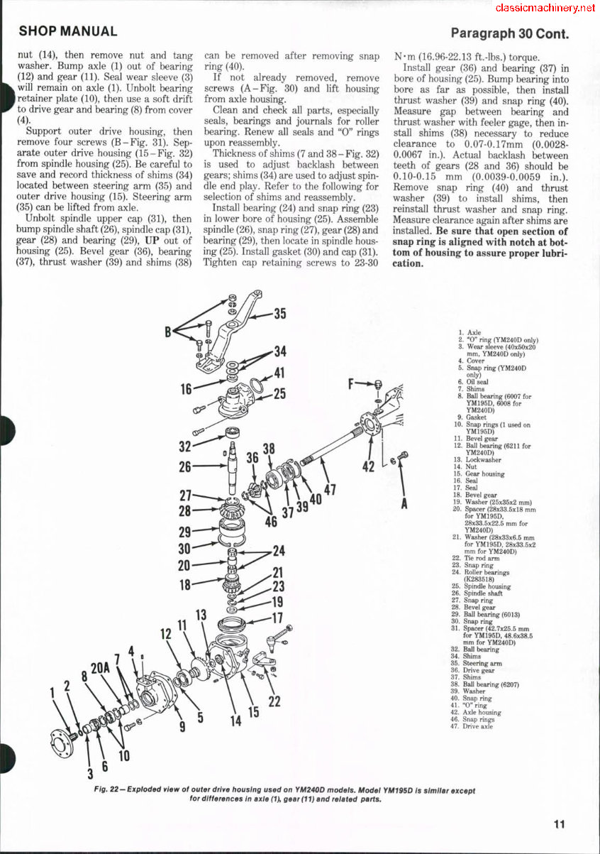
22
1. Axle
2. "0" ring (YM240D only)
3. Wear sleeve (40x50x20
mm, YM240D only)
4. Cover
5. Snap ring (YM240D
only)
6. Oil seal
7. Shims
8. Ball bearing (6007 for
YM195D, 6008 for
YM240D)
9. Gasket
10. Snap rings (1 used on
YM195D)
11. Bevel gear
12. Ball bearing (6211 for
YM240D)
13. Lockwasher
14. Nut
15. Gear housing
16. Seal
17. Seal
18. Bevel gear
19. Washer (25x35x2 mm)
20. Spacer (28x33.5x18 mm
for YM195D,
28x33.5x22.5 mm for
YM240D)
21. Washer (28x33x6.5 mm
for YM195D, 28x33.5x2
mm for YM240D)
22. Tie rod arm
23. Snap ring
24. Roller bearings
(K283518)
25. Spindle houBing
26. Spindle shaft
27. Snap ring
28. Bevel gear
29. Ball bearing (6013)
30. Snap ring
31. Spacer (42.7x25.5 mm
for YM195D, 48.6x38.5
mm for YM240D)
32. Ball bearing
34. Shims
35. Steering arm
36. Drive gear
37. Shims
38. Ball bearing (6207)
39. Washer
40. Snap ring
41. "0" ring
42. Axle housing
46. Snap rings
47. Drive axle
Fig. 22-Exploded view of outer drive housing used on YM240D models. Model YM195D Is simitar except
for differences in axle (1), gear (11) and related parts.
11
You're Reading a Preview
What's Included?
Fast Download Speeds
Online & Offline Access
Access PDF Contents & Bookmarks
Full Search Facility
Print one or all pages of your manual
$41.99
$54.99
Viewed 96 Times Today


Secure transaction
What's Included?
Fast Download Speeds
Online & Offline Access
Access PDF Contents & Bookmarks
Full Search Facility
Print one or all pages of your manual
$41.99
$54.99
This manual is suitable for both first-time owners and amateur enthusiasts, as well as professional technicians. It is designed in an easy-to-read format and provides all the necessary information to perform procedures accurately. Keeping this service manual accessible and referring to it regularly is highly recommended. Regular and preventive maintenance outlined in the manual can effectively save time and money by preventing premature failure and unnecessary repairs.
- BRAKES
- CLUTCH
- COOLING SYSTEM
- DIESEL FUEL SYSTEM
- DIFFERENTIAL
- DIFFERENTIAL LOCK
- ELECTRICAL SYSTEM
- ENGINE
- FINAL DRIVE
- FRONT SYSTEM
- HYDRAULIC SYSTEM
- POWER TAKE-OFF
- TRANSMISSION
File Format: PDF
Compatibility: All Versions of Windows & Mac
Language: English
Requirements: Adobe Reader


