

Oliver 1755, 1855, 1955 Tractor Service & Repair Manual
What's Included?
Fast Download Speeds
Online & Offline Access
Access PDF Contents & Bookmarks
Full Search Facility
Print one or all pages of your manual
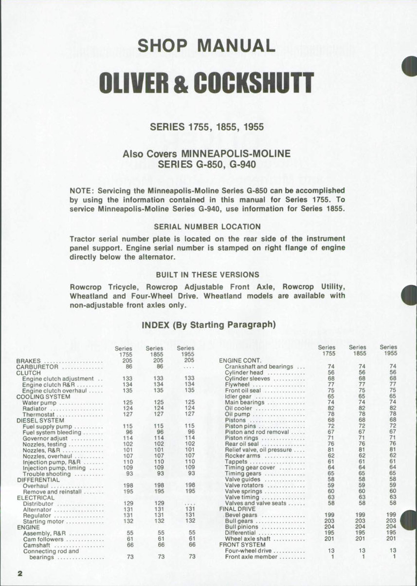
SHOP MANUAL
OLIVER & COCKSHUTT
SERIES 1755, 1855, 1955
Also Covers MINNEAPOLIS-MOLINE
SERIES G-850, G-940
NOTE: Servicing the MInneapolis-Moline Series G-850 can be accomplished
by using the information contained in this manuai for Series 1755. To
service Minneapolis-Moiine Series G-940, use information for Series 1855.
SERiAL NUIVIBER LOCATION
Tractor serial number plate is located on the rear side of the instrument
panel support. Engine serial number is stamped on right flange of engine
directly below the alternator.
BUILT IN THESE VERSIONS
Rowcrop Tricycle, Rowcrop Adjustable Front Axle, Rowcrop Utility,
Wheatland and Four-Wheel Drive. Wheatland models are available with
non-adjustable front axles only.
INDEX (By Starting Paragraph)
Series Series Series
1755 1855 1955
BRAKES 205 205 205
CARBURETOR 86 86
CLUTCH
Engine clutch adjustment .. 133 133 133
Engine clutch R&R 134 134 134
Engine clutch overhaul . 135 135 135
COOLING SYSTEM
Water pump 125 125 125
Radiator 124 124 124
Thermostat 127 127 127
DIESEL SYSTEM
Fuel supply pump , 115 115 115
Fuel system bleeding 96 96 96
Governor adjust 114 114 114
Nozzies. testing 102 102 102
Nozzles, R&R 101 101 101
Nozzles, overhaul 107 107 107
Injection pump, R&R 110 110 110
Injection pump, timing 109 109 109
Troubleshooting 93 93 93
DIFFERENTIAL
Overhaul 198 198 198
Remove and reinstall 195 195 195
ELECTRICAL
Distributor 129 129
Alternator 131 131 131
Regulator 131 131 131
Starting motor 132 132 132
ENGINE
Assembly, R&R 55 55 55
Cam followers 61 61 61
Camshaft 66 66 66
Connecting rod and
bearings 73 73 73
ENGINE CONT,
Crankshaft and bearings
Cylinder head
Cylinder sleeves
Flywheel
Front oil seal
Idler gear
Main bearings
Oil cooler ,.,
Oil pump
Pistons
Piston pins
Piston and rod removal .,
Piston rings
Rear oil seal
Relief valve, oil pressure ,
Rocker arms
Tappets
Timing gear cover
Timing gears
Valve guides
Valve rotators
Valve springs
Valve timing
Valves and valve seats . . .
FINAL DRIVE
Bevel gears
Bull gears
Bull pinions
Differential
Wheel axle shaft
FRONT SYSTEM
Four-wheel drive
Front axle member
Series
1755
74
56
68
77
75
65
74
82
78
68
72
67
71
76
81
62
61
64
65
58
59
60
63
58
199
203
204
195
201
13
1
Series
1855
74
56
68
77
75
65
74
82
78
68
72
67
71
76
81
62
61
64
65
58
59
60
63
58
199
203
204
195
201
13
1
Series
1955
74
56
68
11
75
65
74
82
78
68
72
67
71
76
81
62
61
64
65
58
59
60
63
58
199
203
204
195
201
13
1
Series Series Series
FRONT SYSTEM CONT. 1755 1855 1955
Front boister 4 4 4
Pivot pin 1 1 t
Spindle (knuckle) 6 6 6
Tie rods & toe-in 5 5 5
GOVERNOR
Adjustment, non-diesel 119 119
Adjustment, diesel 114 114 114
Overhaul, non-diesel 123 123
R&R, non-diesel 123 123
HYDRA-POWER 145 145 145
HYDRAUL SHIFT 162 162 162
LIFT SYSTEM, HYDRAULIC
Draft control spring,
adjust 245 245 245
Draft input shaft 266 266 266
Drain and refill 240 240 240
External lift cylinders 271 271 271
Hitch control lever 265 265 265
Hydraulic housing 262 262 262
Lubrication and
maintenance 239 239 239
Cylinder and piston 269 269 269
Manifold 267 267 267
Oil filter 241 241 241
Pump 256 256 256
Series Series Series
LIFT SYSTEM CONT. 1755 1855 1955
Pressure relief valve 249 249 249
Ouick check 237 237 237
Remote cylinders 288 288 288
Remote valves 280 280 280
Rockshaft 263 263 263
Servo valve 267 267 267
System adjustments 243 243 243
Troubleshooting 225 225 225
POWER STEERING 40 40 40
POWER TAKE-OFF
Control valve 219 219 219
Clutch overhaul 217 217 217
Drive shaft,R&R 215 215 215
PTOunit,R&R 216 216 216
TRANSFER DRIVE 32 32 32
TRANSMISSION
Bevel pinion shaft 191 191 191
Countershaft 190 190 190
Input shaft 188 188 188
Lubrication system 176 176 176
Reverse idler 194 194 194
Shifter rails & forks 184 184 184
Top cover 183 183 183
TURBOCHARGER . 117 117
CONDENSED SERVICE DATA
•
Series Series Series
GENERAL 1755 1855 1955
Engine Make Own Own Own
Cylinders, No. of 6 6 6
Cylinder Bore—(nches 37/3 37/8 37/0
Stroke—Inches
Non-Diesel 4 4
Diesel 4% 4% 4%
Displacement—Cubic
Inches
Non-Diesel 283 283
Diesel 310 310 310
Compression Ratio:
Gasoline 8.5:1 8.5-1
Diesel 16.0:1 16.5:1 16.0:1
Main Bearings No. of 7 7 7
Cylinder sleeves Type Wet Wet Wet
Forward Speeds, No. of 6 6 6
Battery Terminal Grounded .. Negative
TUNE-UP
Firing Order 1-5-3-6-2-4
Valve Tappet Gap Inlet:
Non-Diesel : 0.020 0.020 ....
Diesel 0.030 0.030 0.030
Valve Tappet Gap,
Exhaust:
Non-Diesel 0.030 0.030 ....
Diesel 0.030 0.030 0.030
Valve Face Angle, Degrees .. See Par. 58
Valve Seat Angle, Degrees .. See Par. 58
Ignition Distributor Make Holley
Ignition Distributor Model ... —D-2563AA
Generator and Regulator
Make Delco-Remy
Generator Model 1100808
Regulator Model 1119511
Starting Motor Make Delco-Remy
Starting Motor Model:
Non-Diesel 1108431 1108431 ....
Diesel 1113139 1113656 1113656
Ignition Distributor Contact
Gap 0.025 0.025 ....
Ignition Distributor Timing
(Static):
Gasoline 0.025 0.025
Injection Pump Make Roosa-Master
Injection Pump Timing
(Static) 4° 4° T
Carburetor Make -Marvel Schebler- ....
TUNE.UP(Cont.,
Carburetor Model USX-44 USX-37
Engine Low Idle RPM aoo 800
Engine High Idle RPM 2640 2640
Engine Rated RPM ... 2400 2400
PTO RPM @ Engine Rated
RPM:
540 rpm pto 549 549
1000 rpm pto 984 984
SIZES—CLEARANCES—CAPACITIES
Crankshaft Journal Dia 2.624-2 625 —
Crankpin Diameter 2 4365-2 4375
Rod Length 6.749-6.750-
Camshaft Journal Diameter:
Front 1.749-1.750—
Others 1.7485-1.7495
Piston Pin Diameter 1.2494-1.2497
Valve Stem Diameter:
Inlet 0.372-0.373-
Exhaust 0.371-0.372 —
Piston Ring Side
Clearance See Par. 71 —
Main Bearing Clearance 0.0015-0.0045
Rod Bearings Clearance 0.0005-0.0015
Piston Skirt Clearance See Par. 70—
Crankshaft End Play 0.0045-0.0095
Camshaft Bearing
Clearance See Par. 66 —
Cooling System—Gallons 5 5
Engine Crankease
w/filter—Ots 9 9
Fuel Tank, Gasoline—Gals. .. 35 35
Fuel Tank Diesel—Gallons ... 35 35
Transmission and Final
Drive—Ots 43 43
Transfer Case—Quarts 1 1
Hydra-Power Drive—Quarts .. 6 6
Hydraulic Lift—Quarts 27 27
Diff. Housing (4WD)—
Quarts 8 8
Planetary Drive (4WD)—Qts .. 2.5 2.5
TIGHTENING TORQUES—Ft.-Lbs.
Cylinder Head:
Non-Diesel 129-133
Diesel —See Par. 57 —
Main Bearings 129-133
Connecting Rods 44-46
Flywheel 67-69
Series
1955
' 800
2640
2400
549
984
9
35
35
43
1
6
27
8
2.5
Paragraphs 1-2
OLIVER
FRONT SYSTEM (AXLE TYPE)
AXLE MAIN MEMBER AND
PIVOT PIN
Rowcrop Models
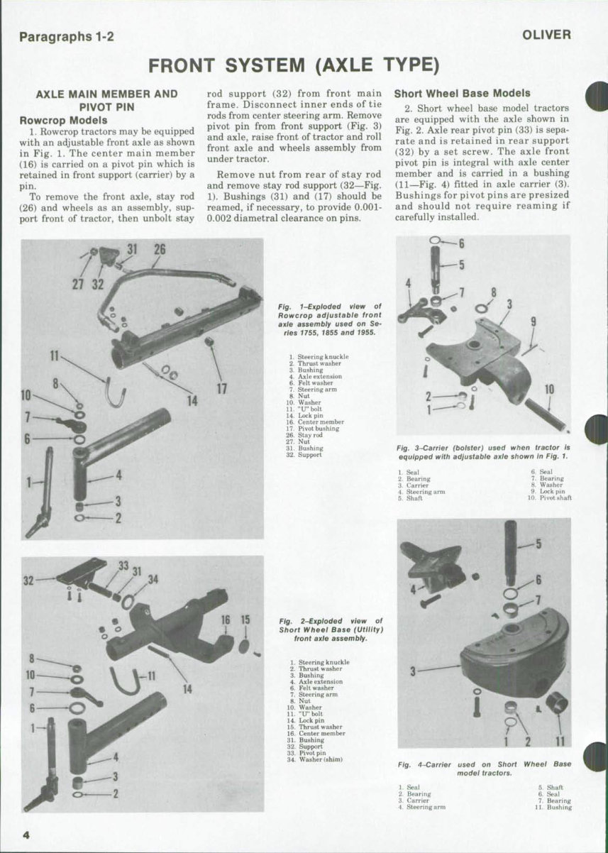
1. Rowcrop tractors may be equipped
with an adjustable front axle as shown
in Fig. 1. The center main member
(16) is carried on a pivot pin which is
retained in front support (carrier) by a
pin.
To remove the front axle, stay rod
(26) and wheels as an assembly, sup-
port front of tractor, then unbolt stay
rod support (32) from front main
frame. Disconnect inner ends of tie
rods from center steering arm. Remove
pivot pin from front support (Fig. 3)
and axle, raise front of tractor and roll
front axle and wheels assembly from
under tractor.
Remove nut from rear of stay rod
and remove stay rod support (32—Fig.
1). Bushings (31) and (17) should be
reamed, if necessary, to provide 0.001-
0.002 diametral clearance on pins.
Fig. 1-Exploded view of
Rowcrop adjustable front
axie assembiy used on Se-
ries 7755, t855 and t955.
1. Steering knuckle
2. Thrust washer
3. Bushing
4. Axle extension
6. Felt washer
7. Steering arm
8. Nut
10 Washer
11. "IT'bolt
14. Lock pin
16. Center member
17. Pivot hushing
26. Stay rod
27. Nut
31. Bushing
32. Support
Ftg. 2-Expioded view of
Short Wheei Base (Utility)
front axle assembiy.
1. Steering knuckle
2. Thrust washer
3. Bushing
4. Axle extension
6. Felt washer
7. Steering arm
8. Nut
10. Washer
11. "IT'holt
14. Lock pin
15. Thrust washer
16. Center memher
31. Bushing
32. Support
33. Pivot pin
34. Washer (shim)
Short Wheel Base Models
2, Short wheel base model tractors
are equipped with the axle shown in
Fig. 2. Axle rear pivot pin (33) is sepa-
rate and is retained in rear support
(32) by a set screw. The axle front
pivot pin is integral with axle center
member and is carried in a bushing
(11—Fig. 4) fitted in axle carrier (3).
Bushings for pivot pins are presized
and should not require reaming if
carefully installed.
O_6
Fig. 3~Carrier (boister) used when tractor is
equipped with adjustable axie shown in Fig. 1.
1. Seal
2. Bearing
3. Carrier
4. Steering arm
5. Shaft
6. Seal
7. Bearing
8. Washer
9. Lock pin
10. Pivot shaft
Fig. 4~Carrier used on Short Wheel Base
modei tractors.
1. Seal
2. Bearing
3. Carrier
4. Steering arm
5. Shaft
6. Seal
7. Bearing
11. Bushing

SERIES 1755-1855-1955
Paragraphs 3-8
To remove front axle and wheels as
an assembly, support front end of
tractor and disconnect tie rods from
center steering arm (4). Remove rear
support (32—Fig. 2) and thrust washer
(15) and slide axle rearward out of
front support (3—Fig. 4). Bushings (11
and 31—Fig. 2) can now be renewed.
When installing bushings, be sure
grease holes in bushings are aligned
with grease fittings.
Be sure to install shim washer (34)
during reassembly.
Wheatland Models
3. Wheatland model tractors have a
non-adjustable front axle which is
fitted with rotating spindles as shown
in Fig. 5.
To remove axle, stay rod (19) and
wheels as an assembly, support front
end of tractor, remove stay rod support
(17) or stay rod nut (22), and discon-
nect tie rods from center steering arm
(4—Fig. 6). Remove cap screw which
retains pivot pin (10) in front support
(3), drive pivot pin from front support
and axle, then raise front of tractor
and roll front axle and wheels as-
sembly from under tractor.
Stay rod bushing and pivot pin
bushing can be renewed and should be
reamed, if necessary, to provide 0.001-
0.002 diametral clearance.
FRONT AXLE CARRIER
Series 1755-1855-1955.
4. Front axle carriers (bolsters) are
shown in Figs. 3, 4 and 6.
To remove front carrier, remove
front axle as outlined in paragraph 1,
2 or 3 and the power steering cylinder
as outlined in paragraph 48, then
unbolt carrier from tractor main
frame.
Remove clamp bolt from steering
arm, then remove steering shaft and
thrust washer (when used) from car-
rier. Remove oil seals, then note loca-
tion of bearings prior to driving them
out. When installing new bearings,
drive or press on lettered end of
bearing cage only and be sure oil holes
in bearing cages are aligned with lu-
brication fittings when bearings are
installed. Seals are installed with lips
toward ends of steering shaft (out-
ward).
TIE RODS and TOE-IN
All Axle Models
5. Tie rod ends are the non-adjust-
able type and are serviced either by
renewing the end assembly or the
complete tie rod assembly.
Toe-in for all axle type models is
3/16-inch. Obtain correct toe-in by
adjusting each tie rod an equal
amount.
STEERING KNUCKLES AND
BUSHINGS
Rowcrop and Short Wheel Base
Models
6. To remove steering knuckles and
renew bushings (3—Fig. 1 or Fig. 2),
support front end of tractor and re-
move tire and wheel assembly.
Straighten tab of washer (10) and
remove nut (8). Remove steering arm
(7) from knuckle and withdraw
knuckle from axle extension (4).
Fig. S~Expioded view of
front axle assembly used on
Wheatiand model tractors.
1. Spindle
2. Wear cup
3. Seal
4. Outer bearing
5. Spindle carrier
6. Plug
7. Bearing
8. Seal
9. Thrust washer
10. Thrust bearing
11. Inner bearing
12. Nut
13. Cotter pin
14. Cap
15. Pivot pin
16. Grease rating
17. Support
18. Bushing
19. Stay rod
20. Main member
21. Bushing
22. Nut
Drive bushings (3) from axle exten-
sion and install new bushings flush
with bore. Bushings are presized and
reaming should not be necessary if
bearings are installed with a suitable
driver.
Thrust washer (2) can be installed
either side up. Insert knuckle into axle
extension, install new felt (6), then on
Rowcrop models, install steering arm
(7) extending to rear and at approxi-
mately 90 degrees to wheel spindle.
On Short Wheel Base models, install
steering arm (7) extending to front at
approximately 90 degrees to wheel
spindle.
LIVE SPINDLES AND SPINDLE
CARRIERS
Wheatland Models
7. SPINDLES. Front wheels on
Wheatland models are attached to live
(rotating) spindles (1—Fig. 5) which
are carried in tapered roller bearings
mounted in the spindle carriers (5).
Spindles can be removed by removing
the cap (14) from inner side of spindle
carrier and removing the cotter pin
(13) and slotted nut (12) from inner
end of spindle. Refer to paragraph 9
for bearing and seal service informa-
tion.
8. SPINDLE CARRIERS. To
renew the spindle carrier pivot pin (15
—Fig. 5) and/or pivot pin needle bear-
ings (7), first remove wheel and dis-
connect tie rod outer end from carrier.
Remove nut from bottom end of pivot
pin and drive the pin up out of axle
(20) and carrier. Drive bearings (7)
from carrier and install new bearings
by driving or pressing on lettered end
of cage only. To renew carrier, remove
O—^8
S~View of carrier used on Wheatland
model tractors.
1. Seal
2. Bearing
3. Carrier
4. Steering arm
5. Shaft
6. Seal
7. Bearing
8. Washer
10. Pivot pin
Paragraphs 9-12
OLIVER
spindle as outlined in paragraph 7.
When reassembling, renew seal (8)
and, if damaged, renew thrust bearing
(10) and washer (9). Refer to para-
graph 9 for wheel bearing and seal
information,
WHEEL BEARINGS AND SEAL
Series 1755-1855-1955
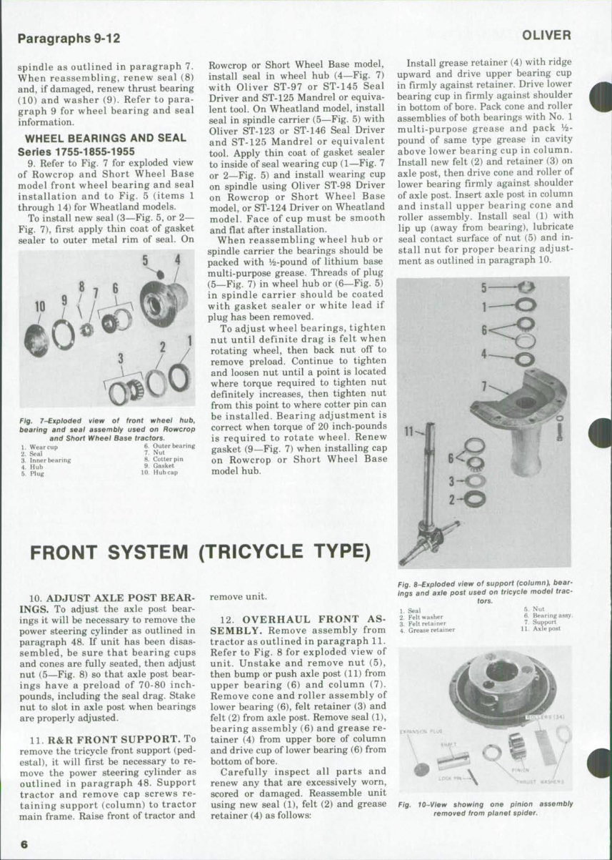
9. Refer to Fig. 7 for exploded view
of Rowcrop and Short Wheel Base
model front wheel bearing and seal
installation and to Fig. 5 (items 1
through 14) for Wheatland models.
To install new seal (3—Fig. 5, or 2—
Fig. 7), first apply thin coat of gasket
sealer to outer metal rim of seal. On
Fig. 7~Expioded view of front wheei hub,
bearing and seat assembly used on Rowcrop
and Short Wheel Base tractors.
1. Wear cup 6. Outer bearing
2. Seal 7. Nut
3. Inner bearing 8. Cotter pin
4. Huh 9- Gasket
5 Plug 10. Hubcap
Rowcrop or Short Wheel Base model,
install seal in wheel hub (4—Fig. 7)
with Oliver ST-97 or ST-145 Seal
Driver and ST-125 Mandrel or equiva-
lent tool. On Wheatland model, install
seal in spindle carrier (5—Fig. 5) with
Oliver ST-123 or ST-146 Seal Driver
and ST-125 Mandrel or equivalent
tool. Apply thin coat of gasket sealer
to inside of seal wearing cup (1—Fig. 7
or 2—Fig. 5) and install wearing cup
on spindle using Oliver ST-98 Driver
on Rowcrop or Short Wheel Base
model, or ST-124 Driver on Wheatland
model. Face of cup must be smooth
and Oat after installation.
When reassembling wheel hub or
spindle carrier the bearings should be
packed with y2-pound of lithium base
multi-purpose grease. Threads of plug
(5—Fig. 7) in wheel bub or (6—Fig. 5)
in spindle carrier should be coated
with gasket sealer or white lead if
plug has been removed.
To adjust wheel bearings, tighten
nut until definite drag is felt when
rotating wheel, then back nut off to
remove preload. Continue to tighten
and loosen nut until a point is located
where torque required to tighten nut
definitely increases, then tighten nut
from this point to where cotter pin can
be installed. Bearing adjustment is
correct when torque of 20 inch-pounds
is required to rotate wheel. Renew
gasket (9—Fig. 7) when installing cap
on Rowcrop or Short Wheel Base
model hub.
Install grease retainer (4) with ridge
upward and drive upper bearing cup
in firmly against retainer. Drive lower
bearing cup in firmly against shoulder
in bottom of bore. Pack cone and roller
assemblies of both bearings with No. 1
multi-purpose grease and pack V2-
pound of same type grease in cavity
above lower bearing cup in column.
Install new felt (2) and retainer (3) on
axle post, then drive cone and roller of
lower bearing firmly against shoulder
of axle post. Insert axle post in column
and install upper bearing cone and
roller assembly. Install seal (1) with
lip up (away from bearing), lubricate
seal contact surface of nut (5) and in-
stall nut for proper bearing adjust-
ment as outlined in paragraph 10.
FRONT SYSTEM (TRICYCLE TYPE)
10. ADJUST AXLE POST BEAR-
INGS. To adjust the axle post bear-
ings it will be necessary to remove tbe
power steering cylinder as outlined in
paragraph 48. If unit has been disas-
sembled, be sure that bearing cups
and cones are fully seated, then adjust
nut (5—Fig. 8) so that axle post bear-
ings have a preload of 70-80 inch-
pounds, including the seal drag. Stake
nut to slot in axle post when bearings
are properly adjusted.
11. R&R FRONT SUPPORT. To
remove tbe tricycle front support (ped-
estal), it will first be necessary to re-
move the power steering cylinder as
outlined in paragraph 48. Support
tractor and remove cap screws re-
taining support (column) to tractor
main frame. Raise front of tractor and
remove unit.
12. OVERHAUL FRONT AS-
SEMBLY. Remove assembly from
tractor as outlined in paragraph 11.
Refer to Fig. 8 for exploded view of
unit, Unstake and remove nut (5),
then bump or push axle post (11) from
upper bearing (6) and column (7).
Remove cone and roller assembly of
lower bearing (6), felt retainer (3) and
felt (2) from axle post. Remove seal (1),
bearing assembly (6) and grease re-
tainer (4) from upper bore of column
and drive cup of lower bearing (6) from
bottom of bore.
Carefully inspect all parts and
renew any that are excessively worn,
scored or damaged. Reassemble unit
using new seal (1), felt (2) and grease
retainer (4) as follows:
4
i
Fig. 8-Expioded view of support (column), bear-
ings and axle post used on tricycle model trac-
tors.
1. Seal
2. Felt washer
3. Felt retainer
4. Grease retainer
5. Nut
6. Bearing assy.
7. Support
11, Axle post
Fig. tO-View showing one pinion assembiy
removed from planet spider.
6

SERIES 1755-1855-1955 Paragraphs 13-16
FRONT SYSTEiVI
(Front-Wheel Drive Axie)
Series 1755,1855 and 1955 tractors are
avaifabie with a front drive axie which is
driven from the transmission bevel pinion
shaft via a transfer case and a drive shaft
fitted with two universal joints. A shifting
mechanism in the transfer case allows
connecting or disconnecting power to the
front drive axie.
Ail four-wheel drive tractors are
equipped with power steering. Aii models
are equipped with a Saginaw Hydramotor
steering unit. Refer to POWER STEERiNG
section for information on the Saginaw
Hydramotor and the two steering cyiin-
ders.
FRONT AXLE AND CARRIER
All Models So Equipped
13. R&R AXLE ASSEMBLY. The
complete front axle assembly can be
removed from tractor as follows: Re-
move drive shaft shield and shield
front support. Disconnect drive shaft
from companion flange of differential
pinion shaft. Disconnect both power
steering cylinders from axle and
spindle supports and lay cylinders on
top of axle carrier. Remove bolts re-
taining axle to axle carrier, then raise
tractor and roll the complete axle and
wheels unit forward and away from
tractor.
Note: A rolling floor jack can be
placed under differential pinion shaft
to keep axle from rotating as tractor is
lifted from axle.
If necessary, wheels and tie-rod can
now be removed and procedure for
doing so is obvious.
Reinstall axle by reversing the re-
moval procedure and be sure piston
rod ends of steering cylinders are at-
tached to steering spindle supports.
Tighten the cylinder attaching bolt
lock nuts until they just contact the
mounting flanges. Further tightening
may distort mounting flanges and
cause cylinder to bind.
14. R&R AXLE CARRIER. To
remove axle carrier, first remove the
front axle as outlined in paragraph 13,
then, secure steering cylinders to
tractor frame. Place a rollingfloorjack
under axle carrier and take weight of
carrier. Remove pivot pin retaining
cap screws, slide pivot pins from pivot
supports and lower the axle carrier
from tractor. If necessary, pivot sup-
ports can be removed from tractor
frame.
Bushings in axle carrier can now be
renewed. Bushings are pre-sized and
should not require reaming if carefully
installed.
15. OVERHAUL FRONT AXLE.
Overhaul of the front drive axle as-
sembly will be discussed as four opera-
tions; the planet spider assembly, the
hub assembly, the spindle support as-
sembly and the differential and carrier
assembly. All operations except the
differential and carrier overhaul can
be accomplished without removing the
front drive axle from tractor. Both
outer ends of axle are identical, hence,
only one outer end will be discussed.
16. PLANET SPIDER. To overhaul
the planet spider assembly, support
outer end of axle and remove the tire
and rim. Remove relief valve from
center of planet spider, remove plug
from wheel hub and drain oil from
planet spider. Remove capscrews that
retain planet spider to wheel hub and
the two puller hole cap screws. Use
two of the removed retaining cap
screws in the puller holes to remove
planet spider assembly from wheel
hub.
With unit removed, remove the
three pinion shaft lock pins by driving
them toward center of unit. Remove
pinion shafts and expansion plugs by
driving pinion shafts toward outside of
planet spider. Remove planet pinions,
rollers (34 in each pinion) and thrust
washers. Discard the expansion plugs.
Refer to Fig. 10.
14
15
Fig. 11-Cross-sectional view
tion axles have a one-p/ecc
1. Internal gear hub
2. Thrust washer
3. Pinion shaft lock pin
6. Wheel hub
7. Hub inner bearing
8. Dirt shield
9. Spindle
10. Spindle support
11. LTp per trunnion
12. Grease fitting
13. Shims
14. Universal joint
15. Upper trunnion bearing
29
showing components of front drive axle outer end. Current produc-
' internal gear and hub instead of the two-piece assembly shown
above.
16. Grease retainer
17. Thrust washer
18. Oil seal
19. Axle shaft (inner)
20. Washer
21. Axle housing
22. Lower trunnion bearing
23. Dust seal retainer
24. Dust seal
25. Spring
26. Felt seal
27. Retainer ring
28. Seal retainer
29. Gasket
30. Shims
31. Lower trunnion
32. Thrust washer
33. Oil seal
34. Oil seal
35. Bushing
36. Axle shaft (outer)
37. Hub outer bearing
38. Thrust washer
39. Innernut
40. Lock washer
41. Outer nut
42. Filler hole plug
43. Planet spider
44. Snap ring
45. Relief valve
46. Sun gear
47. Pinion
48. Pinion rollers
50. Expansion plug
51. Thrust washer
52. Internal gear
Paragraphs 17-21
OLIVER
Clean and inspect all parts and
renew as necessary. Pay particular
attention to the pinion rollers and
thrust washers.
17. When reassembling, use heavy
grease to hold rollers in inner bore of
pinions. Be sure tangs of thrust
washers are in the slots provided for
them and that holes in pinion shaft
and mounting boss are aligned before
pinion shafts are final positioned. Coat
mating surfaces of planet spider and
wheel hub with No, 2 Permatex or
equivalent sealer and install planet
spider in wheel hub. Tighten retaining
cap screws to a torque of 52-57 ft.-lbs.
18. HUB ASSEMBLY, To overhaul
the wheel hub assembly, first remove
planet spider assembly as outlined in
paragraph 16. With planet spider
removed, remove snap ring and sun
gear from outer end of axle shaft.
Straighten tabs of spindle nut lock-
washer, then use OTC tool JD-4 or
equivalent and remove spindle outer
nut and lockwasher. Now loosen but
do not remove the spindle inner nut.
Unbolt spindle from spindle support
and remove wheel hub assembly.
Place hub assembly on bench with
spindle nut on top side and block up
assembly so spindle will be free to
drop several inches. Remove the
spindle inner nut, then place a wood
block over end of spindle and bump
spindle from internal gear hub. Lift
internal gear hub and bearing from
wheel hub and be careful not to allow
bearing to drop from bub of internal
gear bub. Complete removal of spindle
from wheel hub. All bearings and
seals, thrust washers and dirt shield
can now be removed and renewed if
necessary. Bushing and oil seal in
mer bore of spindle (items 33 and 35
"%. 11) can also be renewed at this
Use Fig. 11 as a reference and
ible wheel hub unit as follows:
rearing cups (7 and 37) in hub
allest diameters toward inside
inner bearing in inner
bearing cup, then install oil seal (34)
with lip facing bearing. Bump seal
into bore until it bottoms. Place dirt
shield (8) on hub so flat side is toward
flange of spindle, then using caution
not to damage seal, install spindle in
wheel hub. Hold spindle in that posi-
tion and turn unit over so threaded
end of spindle shaft is on top. Place
outer bearing over end of spindle and
push bearing down into cup. Start
bearing hub of internal gear (1) into
outer bearing cone and, if necessary,
tap gear lightly with a soft faced
hammer to position. Install thrust
washer (38) and spindle inner nut (39)
and tighten nut finger tight. Coat
mating surfaces of spindle and spindle
support with No, 2 Permatex or equiv-
alent sealer and install dirt shield and
spindle on spindle support. Tighten
retaining capscrews to a torque of 80-
88 ft.-lbs.
Adjust inner nut as required until a
pull of 33-38 pounds on a spring scale
attached to a wheel stud is required to
keep hub in motion. See Fig 12. Install
lockwasher (40—Fig, 11) and outer
nut (41), Tighten outer nut and re-
check hub rolling torque. When ad-
justment is correct, bend tabs on lock-
washer to secure both nuts. Install sun
gear (46) and snap ring (44) on outer
end of axle shaft. Coat mating surfaces
of wheel hub and planet spider with
No. 2 Permatex or equivalent sealer
and install planet spider. Tighten re-
taining capscrews to a torque of 52-57
ft.-lbs. Install the puller hole cap-
screws and the tire and rim.
20, SPINDLE SUPPORT, The
spindle support can be serviced after
planet spider and wheel hub assembly
are removed as outlined in paragraphs
16 and 18, However, if service is re-
quired only on the spindle support, the
planet spider, wheel hub and axle
shaft can be removed as a unit as fol-
lows:
Raise outer end of axle and remove
tire and rim. Attach hoist to wheel
stud, then unbolt spindle from spindle
support and pull complete hub as-
sembly and axle shaft from outer end
of axle. Refer to Fig. 16. Do not allow
weight of assembly to be supported by
axle shaft or damage to oil seal in axle
housing outer end will result.
With the complete hub assembly
and axle shaft removed, disconnect tie-
rod and power steering cylinder from
spindle support. Remove the capscrews
from the two-piece retainer ring on
inner side of spindle support and sepa-
rate the retainers, seals and gasket
from spindle support as shown in Fig,
13,
Note: At this time, it is desirable to
remove the grease from cavity formed
by spindle support and outer end of
axle housing.
Remove upper trunnion, pull top of
spindle support outward and remove
spindle support from outer end of axle
housing. Keep shims present under
top trunnion tied to the trunnion for
use during reassembly. Remove upper
trunnion bearing from axle housing.
Remove lower trunnion, shims and
bearing from spindle support. Both
trunnion bearing cups and upper trun-
nion bearing grease retainer can now
be removed if necessary. If necessary
to remove axle shaft thrust washer, oil
seal and oil seal washer from axle
outer end, a slide hammer and puller
attachment can be used. Seals (Fig,
13) on outer end of axle housing can
also be removed at this time.
Clean and inspect all parts and
renew as necessary. It is recommended
that new seals be used during reas-
sembly,
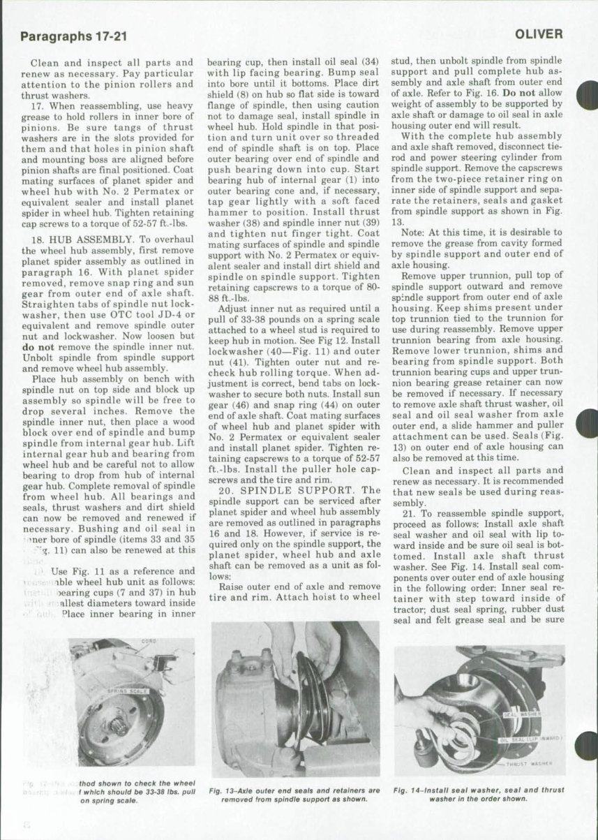
21, To reassemble spindle support,
proceed as follows: Install axle shaft
seal washer and oil seal with lip to-
ward inside and be sure oil seal is bot-
tomed. Install axle shaft thrust
washer. See Fig. 14. Install seal com-
ponents over outer end of axle housing
in the following order: Inner seal re-
tainer with step toward inside of
tractor; dust seal spring, rubber dust
seal and felt grease seal and be sure
thod shown to check the wheel
1 which should be 33-38 ibs. puii
on spring scale.
Fig. 13~Axle outer end seais and retainers are
removed from spindie support as shown.
Fig. 14~lnstatt seat washer, seat and thrust
washer in the order shown.
SERIES 1755-1855-1955
Paragraphs 22-23
bevel in inside diameter of both seals
is toward bell of axle outer end; outer
seal retainer with step toward outside
of tractor and gasket. Install grease
retainer (cup side up) and upper
bearing cup (smallest LD. down) in the
upper trunnion bearing bore. Bolt
lower trunnion to spindle support
using original shims and tighten cap
screws to a torque of 80-88 ft.-lbs.
Place lower trunnion bearing over
lower trunnion. Install lower trunnion
bearing cup in outer end of axle
housing with smallest LD. of cup up.
Place upper trunnion bearing in the
upper trunnion bearing cup, then
while tipping upper side of spindle
support slightly outward, position
spindle support over outer end of axie
housing and install upper trunnion
with original shim pack. Tighten trun-
nion retaining cap screws to a torque
of 80-88 ft.-lbs.
Before attaching tie-rod, power
steering cylinder or seal assembly to
spindle support, check adjustment of
trunnion bearings as follows: Connect
a spring pull scale to tie-rod hole of
spindle support and check pull re-
quired to rotate the spindle support.
Refer to Fig. 15. Adjustment is correct
when 12 to 18 pounds pull is required.
To adjust bearings, vary number of
shims located under the trunnions as
required to obtain proper adjustment
keeping the total thickness of shims
under the top trunnion and lower
trunnion as equal as possible. Shims
are available in thicknesses of 0.003,
0.005 and 0.010.
Use grease to hold seal retainer
gasket in place, then install seal as-
sembly on spindle support, being sure
that the split ends of outer seal as-
sembly do not align. Attach tie-rod
and tighten tie-rod stud nut to a
torque of 200 ft.-lbs. Attach power
steering cylinder and tighten at-
taching bolt lock nut until it just con-
tacts mounting flange.
Place approximately four pounds of
grease in the cavity of spindle support
and pack universal joint of axle shaft.
Coat mating surfaces of spindle and
spindle support with No. 2 Permatex
or equivalent sealer and install the
planet spider, wheel hub and axle as-
sembly on the spindle support.
Tighten attaching capscrews to a
torque of 80-88 ft.-lbs. Then, install
tire and rim.
DIFFERENTIAL AND CARRIER
The Four Wheei Drive front axie can be
equipped with either a conventionai dif-
ferentiai assembiy or a "No-Spin" differ-
entiai assembiy. Removai procedure wili
be the same for both types. For service
Information, refer to paragraphs 23 and
27.
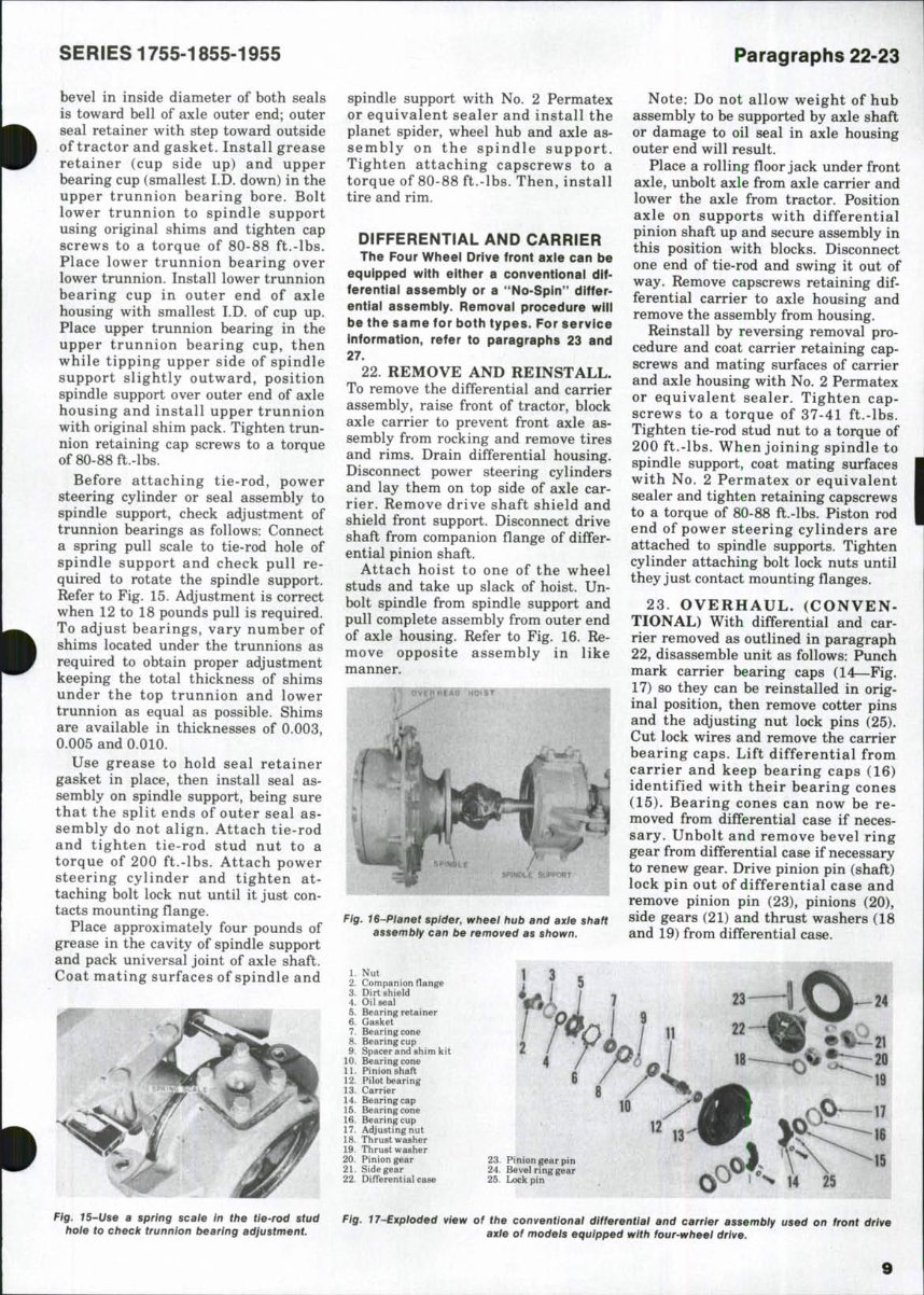
22. REMOVE AND REINSTALL.
To remove the differential and carrier
assembly, raise front of tractor, block
axle carrier to prevent front axle as-
sembly from rocking and remove tires
and rims. Drain differential housing.
Disconnect power steering cylinders
and lay them on top side of axle car-
rier. Remove drive shaft shield and
shield front support. Disconnect drive
shaft from companion flange of differ-
ential pinion shaft.
Attach hoist to one of the wheel
studs and take up slack of hoist. Un-
bolt spindle from spindle support and
pull complete assembly from outer end
of axle housing. Refer to Fig. 16. Re-
move opposite assembly in like
manner.
Fig. 16~Pianet spider, wheei hub and axie shaft
assembly can be removed as shown.
1. Nut
2. Companion flange
3. Dirt shield
4. Oil seal
5. Bearing retainer
6. Gasket
7. Bearing cone
8. Bearing cup
9. Spacer and shim kit
10. Bearing cone
11. Pinion shaft
12. Pilot bearing
13. Carrier
14. Bearing cap
15. Bearing cone
16. Bearing cup
17. Adjusting nut
18. Thrust washer
19. Thrust washer
20. Pinion gear
21. Side gear
22. Differential case
Note: Do not allow weight of hub
assembly to be supported by axle shaft
or damage to oil seal in axle housing
outer end will result.
Place a rolling floor jack under front
axle, unbolt axle from axle carrier and
lower the axle from tractor. Position
axle on supports with differential
pinion shaft up and secure assembly in
this position with blocks. Disconnect
one end of tie-rod and swing it out of
way. Remove capscrews retaining dif-
ferential carrier to axle housing and
remove the assembly from housing.
Reinstall by reversing removal pro-
cedure and coat carrier retaining cap-
screws and mating surfaces of carrier
and axle housing with No. 2 Permatex
or equivalent sealer. Tighten cap-
screws to a torque of 37-41 ft.-lbs.
Tighten tie-rod stud nut to a torque of
200 ft.-lbs. When joining spindle to
spindle support, coat mating surfaces
with No. 2 Permatex or equivalent
sealer and tighten retaining capscrews
to a torque of 80-88 ft.-lbs. Piston rod
end of power steering cylinders are
attached to spindle supports. Tighten
cylinder attaching bolt lock nuts until
they just contact mounting flanges.
23. OVERHAUL. (CONVEN-
TIONAL) With differential and car-
rier removed as outlined in paragraph
22, disassemble unit as follows: Punch
mark carrier bearing caps (14—Fig.
17) so they can be reinstalled in orig-
inal position, then remove cotter pins
and the adjusting nut lock pins (25).
Cut lock wires and remove the carrier
bearing caps. Lift differential from
carrier and keep bearing caps (16)
identified with their bearing cones
(15). Bearing cones can now be re-
moved from differential case if neces-
sary. Unbolt and remove bevel ring
gear from differential case if necessary
to renew gear. Drive pinion pin (shaft)
lock pin out of differential case and
remove pinion pin (23), pinions (20),
side gears (21) and thrust washers (18
and 19) from differential case.
23. Pinion gear pin
24. Bevel ringgear
25. Lock pin
25
Fig. 15-Use a spring scaie In the tie-rod stud
hole to check trunnion bearing adjustment.
Fig. 17-Exploded view of the conventionai differential and carrier assembiy used on front drive
axie of models equipped with four-wheei drive.
9

Paragraphs 24-28
OLIVER
Remove cotter pin and nut (1) from
pinion shaft (11), then using a puller,
remove the companion flange (2) and
dust shield. Remove pinion shaft
bearing retainer (5) and press pinion
shaft and bearing from carrier. Use a
split bearing puller to support pinion
bearing cup (8) on edge nearest pinion
shaft gear and press pinion shaft from
rear bearing and bearing cup. Remove
spacer (9) and any shims which may
be present from pinion shaft. Remove
front bearing and inner (pilot) bearing
(12) in a similar manner.
Clean and inspect all parts. Pay par-
ticular attention to bearings, bearing
cups and thrust washers. If any of the
differential side gears or pinions are
damaged or excessively worn, renew
all gears and thrust washers. Pinion
shaft and bevel ring gear are available
in a matched set only.
24, The differential and carrier unit
is assembled as follows: Place inner
(pilot) bearing on inner end of pinion
shaft and stake in four places. Use a
piece of pipe the size of inner pinion
shaft bearing race to press forward
bearing cone (10) onto shaft with taper
facing threaded end of pinion shaft.
Place bearing spacer and any shims
which were present during disas-
sembly over pinion shaft, then position
the bearing cup over forward bearing.
Press the rear pinion shaft bearing (7)
on shaft with taper away from
threaded end of pinion shaft. Check
and, if necessary, renew the dust
shield (3) on companion flange. Posi-
tion companion flange so it will not
obstruct cotter pin hole in end of
pinion shaft, slide bearing retainer oil
seal on its land on companion flange,
then press companion flange on pinion
shaft. Install retaining nut, clamp
companion flange in a vise and tighten
nut to a torque of 300 ft.-lbs.
Note: Pressure of oil seal will gener-
ally hold bearing retainer away from
bearing. If it does not do so, tie re-
tainer to companion flange.
25, With pinion shaft assembled as
outlined above, clamp the bearing cup
in a soft jawed vise just tight enough
to prevent rotation, then using an
inch-pound torque wrench on com-
panion flange retaining nut, check
torque required to rotate pinion shaft.
Pinion shaft bearing adjustment is
correct if 13 to 23 inch-pounds is re-
quired to rotate shaft. If rolling torque
is not as specified, disassemble the
pinion shaft assembly and vary thick-
ness of spacer and/or shims as re-
quired to obtain proper rolling torque,
A spacer and shim kit is available
under Oliver part number 155 342-A.
With pinion shaft assembled and
correct rolling torque (bearing adjust-
ment) obtained, press pinion shaft as-
sembly into carrier, install bearing
retainer and tighten capscrews to a
torque of 25 ft,-lbs. Install cotter pin to
lock the nut in place,
26, Reassemble differential case
assembly as follows: Place side gears,
pinions and thrust washers in differ-
ential case and install pinion pin
(shaft). Secure pinion pin with lock pin
and, if lock pin is straight type, stake
pin in position. It is not necessary to
stake the spring type lock pin. If bevel
ring gear was removed, reinstall with
bolt heads on ring gear side of as-
sembly and tighten the nuts to a
torque of 78-86 ft,-lbs. Press bearings
on differential case with tapers facing
away from case. Place bearing cups
over differential bearings and place
differential assembly in carrier. Posi-
tion bearing adjusting nuts in carrier
and install the carrier bearing caps.
Tighten the bearing cap screws until
caps are snug but be sure threads of
caps and adjusting nuts are in reg-
ister. Maintain some clearance be-
tween gear teeth and tighten ad-
justing nuts until bearing cups are
seated and all end play of differential
is eliminated. Mount a dial indicator
and shift differential assembly as re-
quired to obtain a backlash of 0,008-
0,011 between bevel pinion shaft and
bevel ring gear. Differential is shifted
by loosening one adjusting nut and
tightening the opposite nut an equal
amount. Note: Mesh position of the
bevel pinion shaft is not adjustable.
With gear backlash adjusted,
tighten the bearing cap retaining cap-
screws to a torque of 65 ft,-lbs, and
secure with lock wire. Install ad-
justing nut lock pins and cotter pins.
Note: If lock pins will not enter slots
of adjusting nuts after backlash ad-
justment has been made, tighten
rather than loosen the adjusting nut,
or nuts. Recheck gear backlash.
Fig. 18~Exptoded view of
the 'nO'Spin" differentiat
case assembiy a v ait able for
the four-wheel drive front
axle.
1. Case half
2. Side gear
3. Spring
4. Spring retainer
5. Driven center
6. Hold-out ring
7. Central driver & center cam
8. Case half
If used, install thrust screw and
turn screw in until it contacts back
side of bevel ring gear, then back
screw out ^^ to y2-turn. Apply sealer to
threads of thrust screw at surface of
carrier, then while holding screw from
turning, install locking washer and
nut. Secure nut by bending one tang of
locking washer over nut and another
tang over boss of carrier,
27. OVERHAUL (NO-SPIN). With
differential and carrier removed as
outlined in paragraph 22, unit is dis-
assembled as follows: Punch mark the
carrier bearing caps (14—Fig, 17) so
they can be reinstalled in their orig-
inal positions, then remove cotter pins
and the adjusting nut lock pins (25),
Cut lock wires and remove the carrier
bearing caps. Lift differential from
carrier and keep bearing cups (16)
identified with their bearing cones
(15), Bearing cones can now be re-
moved from differential case, if neces-
sary.
Remove cotter pin and nut (1) from
pinion shaft (11), then using a puller,
remove the companion flange (2) and
dust shield. Remove pinion shaft
bearing retainer (5) and press shaft
and bearings from carrier. Use a split
bearing puller to support pinion
bearing cup (8) on edge nearest pinion
shaft gear and press pinion shaft from
rear bearing (7) and bearing cup.
Remove spacer (9) and any shims
which may be present from pinion
shaft. Remove front bearing (10) and
inner (pilot) bearing (12) in a similar
manner.
Unbolt and remove bevel ring gear
from differential, if necessary. Remove
differential case bolts and hold case
together as last bolt is removed to
keep assembly from flying apart due
to the internal spring pressure. See
Fig. 18, Hold out rings (6) can be re-
moved with snap ring spreaders,
28, Clean and inspect all parts.
Check splines on side gears and clutch
members and remove any burrs or
4
•
10
SERIES 1755-1855-1955 Paragraphs 29-31
chipped edges with a stone or burr
grinder. Renew any parts which have
sections of splines broken away. In-
spect springs (3) for fractures, or other
damage, and renew springs which do
not have a free height of 2V4-2^
inches. Center cam in central driver
(7) must be free to rotate within the
limits of keys in central driver. Check
the weld between driven clutch (5) and
cam ring on clutch by tapping lightly
on cams of cam ring. If cam ring ro-
tates in driven clutch, weld is defec-
tive (failed). Inspect teeth on central
driver and driven clutches. Small de-
fects can be dressed with a stone. If
central driver or driven clutch is re-
newed, also renew the part it mates
with. A smooth wear pattern up to 50
percent of face width is acceptable for
the cams on center cam and driven
clutch.
29. The differential and carrier unit
is assembled as follows: Place the
inner (pilot) bearing on inner end of
pinion shaft and stake in four places.
Use a piece of pipe the size of inner
race of pinion shaft bearing and press
the forward pinion shaft bearing (10—
Fig. 17) on shaft with taper facing
threaded end of pinion shaft. Place
bearing spacer, and any shims which
were present during disassembly over
pinion shaft, then position the bearing
cup over forward bearing. Press the
rear pinion shaft bearing (7) on shaft
with taper away from threaded end of
pinion shaft. Check, and renew if nec-
essary, the oil seal (4) in pinion shaft
bearing retainer (5). Seal is installed
with lip toward inside. Place gasket
and bearing retainer over pinion shaft.
Check, and renew if necessary, the
dust shield (3) on companion flange.
Position companion flange so it will
not obstruct cotter pin hole in end of
pinion shaft, slide bearing retainer oil
seal on its land on companion flange,
then press companion flange on pinion
shaft. Install retaining nut, clamp
companion flange in a vise and tighten
nut to a torque of 300 ft.-lbs.
NOTE: Pressure of oil seal will gen-
erally hold bearing retainer away
from bearing. If it does not, tie re-
tainer to companion flange.
30. With pinion shaft assembled as
outlined above, clamp the bearing cup
in a soft jawed vise only tight enough
to prevent rotation, then using an
inch-pound torque wrench attached to
companion flange retaining nut, check
the rolling torque (bearing preload) of
the pinion shaft. This rolling torque
should be 13-23 in.-lbs.
If rolling torque is not as specified,
it will be necessary to disassemble the
shaft assembly and vary the spacer
and/or shims as required. A spacer and
shim kit is available under Oliver part
number 155 342-A.
With pinion shaft assembled and the
rolling torque of shaft determined,
press pinion shaft assembly into car-
rier, install bearing retainer and
tighten cap screws to a torque of 25 ft.-
lbs. Install cotter pin to lock nut (1) in
place.
31. Lubricate all parts and reas-
semble no-spin differential by re-
versing disassembly procedure. Be
sure to position spring retainers so
that spring seats inside cupped section
of retainer. Be sure key in central
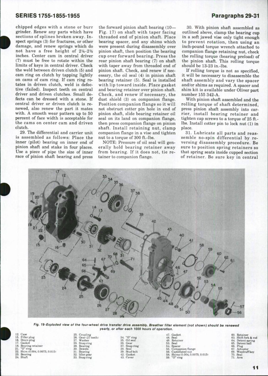
Fig. 19~Exploded view of the four-wheei drive transfer drive assembiy. Breather filter eiement (not shown) should be renewed
yearly, or after each 1000 hours of operation.
12. Case
15. Filler plug
16. Drain plug
17. Gasket
18. Bearing retainer
21. "O"ring
22. Shim (0.004, 0.0075, 0.015)
23. Bearing
24. Shaft
25. Coupling
26. Gear (27 teeth)
27. Washer
28. Snap ring
29. Bearing
30. I>owels
31. Bearing
32. Idler gear
33. Snap ring
34. "O"ring
35. Oil seal
36. Gear
37. Snap ring
38. Seal
39. Stud bolt
42. Gasket
43. Cover
47. Gasket
48. Seal
49. Retainer
53. Seal
54. Spacer
55. Companion flange
56. Castellated nut
58. Shims (0.004,0.0075, 0.015)
59. "O"ring
60. Retainer
63. Shift fork & rod
64. Detent spring
65. Detent ball
66. Plug
67. Actuator
69. Woodruffkey
70. Seal
71. Arm
11
You're Reading a Preview
What's Included?
Fast Download Speeds
Online & Offline Access
Access PDF Contents & Bookmarks
Full Search Facility
Print one or all pages of your manual
$39.99
Viewed 96 Times Today


Secure transaction
What's Included?
Fast Download Speeds
Online & Offline Access
Access PDF Contents & Bookmarks
Full Search Facility
Print one or all pages of your manual
$39.99
- Complete Factory Service Repair Workshop Manual
- Available for instant access on your computer, tablet, or smartphone
- Professional Manual covering all repairs, servicing, and troubleshooting procedures
- Contains detailed photos & diagrams
- Used by professional Mechanics and Technicians
- Can be printed out in full or in part
- Can be used on multiple computers
- Full Manual without any limitations or trial periods
- No expiration or renewal fees
- Fully compatible with Windows & MAC computers
Thanks for looking at this item, please click on the Button.


