Ford New Holland 1700 Tractor Owners Operators Maintenance Manual - IMPROVED -
What's Included?
Lifetime Access
Fast Download Speeds
Online & Offline Access
Access PDF Contents & Bookmarks
Full Search Facility
Print one or all pages of your manual
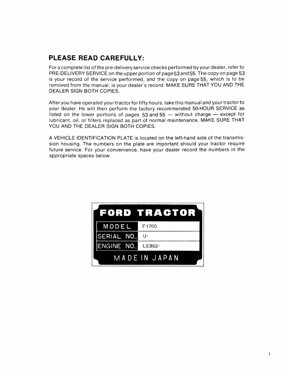
PLEASE READ CAREFULLY: For a complete list of the pre-delivery service checks performed by your dealer, refer to PRE-DELIVERY SERVICE on the upper portion of page 53 and 55. The copy on page 53 is your record of the service performed, and the copy on page 55, which is to be removed from the manual, is your dealer's record. MAKE SURE THAT YOU AND THE DEALER SIGN BOTH COPIES. After you have operated your tractor for fifty hours, take this manual and your tractor to your dealer. He will then perform the factory recommended 50-HOUR SERVICE as listed on the lower portions of pages 53 and 55 - without charge - except for lubricant, oil, or filters replaced as part of normal maintenance. MAKE SURE THAT YOU AND THE DEALER SIGN BOTH COPIES. A VEHICLE IDENTIFICATION PLATE is located on the left-hand side of the transmis- sion housing. The numbers on the plate are important should your tractor require future service. For your convenience, have your dealer record the numbers in the appropriate spaces below. FORD TRACTOR MODEL F1700 SERIAL NO., u- ENGINE NO., LE892- MADE IN JAPAN
- 2
CONTENTS INTERNATIONAL SYMBOLS ....................................................... 4 SAFETY PRECAUTIONS ........................................................... 5 CONTROLS AND INSTRUMENTS .................................................. 6-11 SEAT, LIGHT AND ENGINE CONTROLS ................................................. 6 LIGHTING ..................................................................... 6·7 INSTRUMENT PANEL ................................................... - .......... 7-8 THROTTLE CONTROLS ............................................................ 8 BRAKE CONTROLS .............................................................. 8-9 DIFFERENTIAL CONTROL .......................................................... 9 TRANSMISSION AND PTO CONTROLS ................................................ 9-11 HYDRAULIC LIFT SYSTEM CONTROLS ............................................... 11-12 OPERATION ........ ,- .......................................................... 13·22 BREAK-IN PROCEDURES .......................................................... 13 STARTING THE ENGINE ......................................................... 13-14 STOPPING THE ENGINE ........................................................... 14 OPERATING THE TRANSMISSION, FOUR-WHEEL DRIVE AND PTO ............................................................. 14-16 TOWING THE TRACTOR ........................................................... 16 OPERATING THE DIFFERENTIAL LOCK ............................................. 16-17 OPERATING THE HYDRAULIC LIFT SYSTEM .......................................... 17·19 DRIVING THE TRACTOR .......................................................... 19 WHEEL TREAD SETTINGS ....................................................... 20-21 TRACTOR WEIGHTING .......................................................... 21-22 TIRE PRESSURES ................................................................ 22 LUBRICATION AND MAINTENANCE ............................................. 23-43 LUBRICATION AND MAINTENANCE CHART .......................................... 23-24 TWO-WHEEL DRIVE ............................................................. 23 FOUR-WHEEL DRIVE ............................................................ 24 FUEL AND LUBRICANTS ................................... _ .................... 25-27 FUEL AND LUBRICANT SERVICE PROCEDURES ....................................... 27-30 GENERAL MAINTENANCE ....................................................... 30-41 TRACTOR STORAGE ........................................................... 41-42 GENERAL TORQUE SPECIFICATION TABLE ............................................ 43 SPECIFICATIONS .............................................................. 44-47 SAFETY AND INSTRUCTION DECALS ............................................ 48-50 PREDELIVERY AND 50-HOUR SERVICE .......................................... 53,55 3
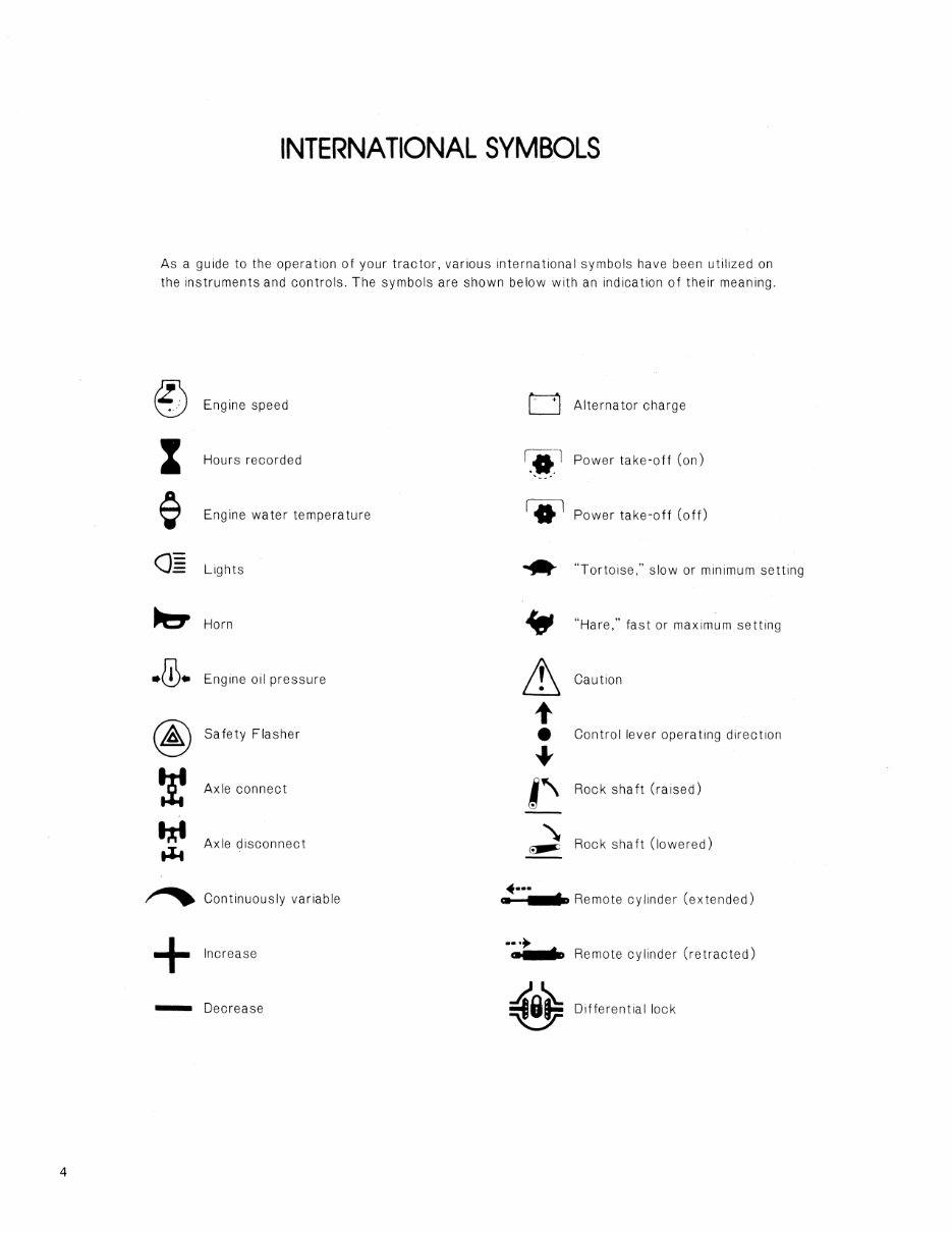
4 INTERNATIONAL SYMBOLS As a guide to the operation of your tractor, various international symbols have been utilized on the instruments and controls. The symbols are shown below with an indication of their meaning. Engine speed 0 Alternator charge Z Hours recorded r:a-l '*. Power take-off (on) Engine water temperature 10 1 Power take-off (off) ()= Lights .. "Tortoise," slow or minimum setting Horn • "Hare," fast or maximum setting .. lj). Engine oil pressure & Caution @ t Safety Flasher • Control lever operating direction + Axle connect I" Rock shaft (raised) Axle disconnect " Rock shaft (lowered) t-i4 Continuously variable •••• $ Remote cylinder (extended) III + •••• $ Remote cylinder (retr·acted) Increase III - Decrease ;§O'e -cr Differential lock
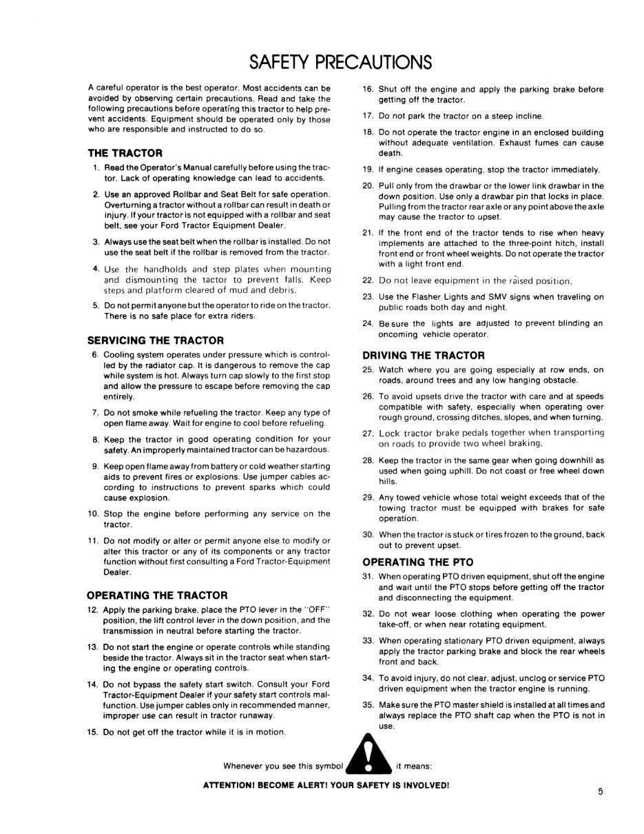
SAFETY PRECAUTIONS A careful operator is the best operator. Most accidents can be avoided by observing certain precautions. Read and take the following precautions before operating this tractor to help pre- vent accidents. Equipment should be operated only by those who are responsible and instructed to do so. THE TRACTOR 1. Read the Operator's Manual carefully before using the trac- tor. Lack of operating knowledge can lead to accidents. 2. Use an approved Rollbar and Seat Belt for safe operation. Overturning a tractor without a roll bar can result in death or injury. If your tractor is not equipped with a rollbar and seat belt, see your Ford Tractor Equipment Dealer. 3. Always use the seat belt when the roll bar is installed. Do not use the seat belt if the roll bar is removed from the tractor. 4. Use the handholds and step plates when mounting and dismounting the tactor to prevent falls. Keep steps and platform cleared of mud and debris. 5. Do not permit anyone but the operator to ride on the tractor. There is no safe place for extra riders. SERVICING THE TRACTOR 6. Cooling system operates under pressure which is control- led by the radiator cap. It is dangerous to remove the cap while system is hot. Always turn cap slowly to the first stop and allow the pressure to escape before removing the cap entirely. 7. Do not smoke while refueling the tractor. Keep any type of open flame away. Wait for engine to cool before refueling. 8. Keep the tractor in good operating condition for your safety. An improperly maintained tractor can be hazardous. 9. Keep open flame away from battery or cold weather starting aids to prevent fires or explosions. Use jumper cables ac- cording to instructions to prevent sparks which could cause explosion. 10. Stop the engine before performing any service on the tractor. 11. Do not modify or alter or permit anyone else to modify or alter this tractor or any of its components or any tractor function without first consulting a Ford Tractor-Equipment Dealer. OPERATING THE TRACTOR 12. Apply the parking brake, place the PTO lever in the "OFF" position, the lift control lever in the down position, and the transmission in neutral before starting the tractor. 13. Do not start the engine or operate controls while standing beside the tractor. Always sit in the tractor seat when start- ing the engine or operating controls. 14. Do not bypass the safety start switch. Consult your Ford Tractor-Equipment Dealer if your safety start controls mal- function. Use jumper cables only in recommended manner, improper use can result in tractor runaway. 16. Shut off the engine and apply the parking brake before getting off the tractor. 17. Do not park the tractor on a steep incline. 18. Do not operate the tractor engine in an enclosed building without adequate ventilation. Exhaust fumes can cause death. 19. If engine ceases operating, stop the tractor immediately. 20. Pull only from the drawbar or the lower link drawbar in the down position. Use only a drawbar pin that locks in place. Pulling from the tractor rear axle or any point above the axle may cause the tractor to upset. 21. If the front end of the tractor tends to rise when heavy implements are attached to the three-point hitch, install front end or front wheel weights. Do not operate the tractor with a light front end. 22. Do not leave equipmentin the raised position. 23. Use the Flasher Lights and SMV signs when traveling on public roads both day and night. 24. Be sure the lights are adjusted to prevent blinding an oncoming vehicle operator. DRIVING THE TRACTOR 25. Watch where you are going especially at row ends, on roads, around trees and any low hanging obstacle. 26. To avoid upsets drive the tractor with care and at speeds compatible with safety, especially when operating over rough ground, crossing ditches, slopes, and when turning. 27. Lock tractor brake pedals together when transporting on roads to provide two wheel braking. 28. Keep the tractor in the same gear when going downhill as used when going uphill. Do not coast or free wheel down hills. 29. Any towed vehicle whose total weight exceeds that of the towing tractor must be equipped with brakes for safe operation. 30. When the tractor is stuck or tires frozen to the ground, back out to prevent upset. OPERATING THE PTO 31. When operating PTO driven equipment, shut off the engine and wait until the PTO stops before getting off the tractor and disconnecting the eqUipment. 32. Do not wear loose clothing when operating the power take-off, or when near rotating equipment. 33. When operating stationary PTO driven equipment, always apply the tractor parking brake and block the rear wheels front and back. 34. To avoid injury, do not clear, adjust, unclog or service PTO driven equipment when the. tractor engine is running. 35. Make sure the PTO master shield is installed at all times and always replace the PTO shaft cap when the PTO is not in use. 15. Do not get off the tractor while it is in motion. A. Whenever you see this SymbOl" it means: AnENTIONI BECOME ALERTI YOUR SAFETY IS INVOLVEDI 5
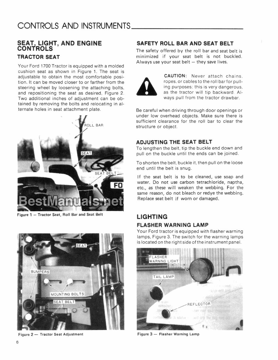
CONTROLS AND INSTRUMENTS ________ _ SEA1 LIGHT, AND ENGINE CON I ROLS TRACTOR SEAT Your Ford 1700 Tractor is equipped with a molded cushion seat as shown in Figure 1. The seat is adjustable to obtain the most comfortable posi- tion. It can be moved closer to or farther from the steering wheel by loosening the attaching bolts, and repositioning the seat as desired, Figure 2. Two additional inches of adjustment can be ob- tained by removing the bolts and relocating in al- ternate holes in seat attachment plate. Figure 1 - Tractor Seat, Roll Bar and Seat Belt Figure 2 - Tractor Seat Adjustment 6 SAFETY ROLL BAR AND SEAT BELT The safety offered by the roll bar and seat belt is minimized if your seat belt is not buckled. Always use your seat belt - they save lives. CAUTION: Never attach chains, ropes, or cables to the roll bar for pull- ing purposes: this is very dangerous, as the tractor will tip backward. Al- ways pull from the tractor drawbar. Be careful when driving through door openings or under low overhead objects. Make sure there is sufficient clearance for the roll bar to clear the structure or object. ADJUSTING THE SEAT BELT To lengthen the belt, tip the buckle end down and pull on the buckle until the ends can be joined. To shorten the belt, buckle it, then pull on the loose end until the belt is snug. If the seat belt is to be cleaned, use soap and water. Do not use carbon tetrachloride, naptha, etc., as these will weaken the webbing. For the same reason, do not bleach or redye the webbing. Replace seat belt if worn or damaged. LIGHTING FLASHER WARNING LAMP Your Ford tractor is equipped with flasher warning lamps, Figure 3. The switch for the warning lamps is located on the right side of the instrument panel. Figure 3 - Flasher Warning Lamp
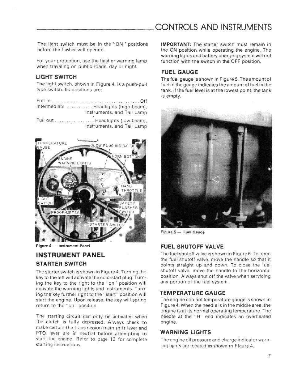
_________ CONTROLS AND The light switch must be in the "ON" positions before the flasher wiil operate. For your protection, use the flasher warning lamp when traveling on public roads, day or night. LIGHT SWITCH The light switch, shown in Figure 4, is a push-pull type switch. Its positions are: Full in ..................................... Off Intermediate ........... Headlights (high beam), Instruments, and Tail Lamp Full out ................ '. Headlights (low beam), Instruments, and Tail Lamp Figure 4 - Instrument Panel INSTRUMENT PANEL STARTER SWITCH The starter switch is shown in Figure 4. Turning the key to the left will activate the cold-start plug. Turn- ing the key to the right to the "on" position will activate the warning lights and instruments. Turn- ing the key further right to the "start" position will start the engine. Upon release, the key will spring return to the "on' position. The starting circuit can only be activated when the clutch is fully depressed. Always check to make certain the transmission main shift lever and PTa lever are in neutral before attempting to start the engine. Refer to page 13 for complete starting instructions. IMPORTANT: The starter switch must remain in the ON position while operating the engine. The warning lights and battery charging system will not function with the switch in the OFF position. FUEL GAUGE The fuel gauge is shown in Figure 5. The amount of fuel in the gauge indicates the amount of fuel in the tank. If the fuel level is at the lowest point, the tank is empty. Figure 5 - Fuel Gauge FUEL SHUTOFF VALVE The fuel shutoff valve is shown in Figure 6. To ope.n the fuel shutoff valve, move the handle so that 'it points straight up and down, To close the fuel shutoff valve, move the handle to the horizontal position. Always shut off the valve when servicing any portion of the fuel system. TEMPERATURE GAUGE The engine coolant temperature gauge is shown in Figure 4. When the needle is in the middle area, the engine is at its normal operating temperature. The needle at the "H" end indicates an overheated engine. WARNING LIGHTS The engine oil pressure and charge indicator warn- ing lights are located as shown in Figure 4. 7
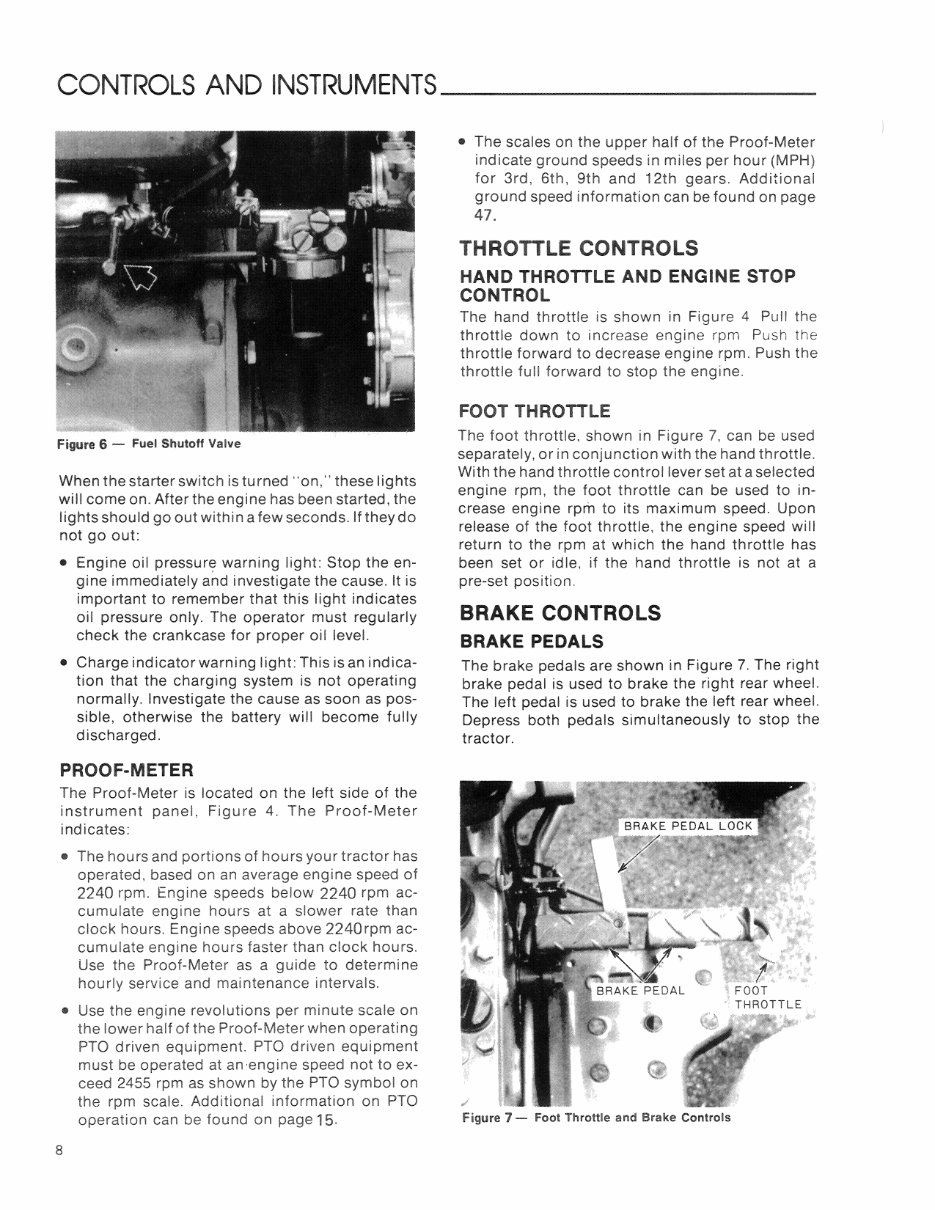
CONTROLS AND INSTRUMENTS ________ _ Figure 6 - Fuel Shutoff Valve When the starter switch is turned "on," these lights will come on. After the engine has been started, the lights should go out within a few seconds. If they do not go out: • Engine oil warning light: Stop the en- gine immediately and investigate the cause. It is important to remember that this light indicates oil pressure only. The operator must regularly check the crankcase for proper oil level. • Charge indicator warning light: This is an indica- tion that the charging system is not operating normally. Investigate the cause as soon as pos- sible, otherwise the battery will become fully discharged. PROOF-METER The Proof-Meter is located on the left side of the instrument panel, Figure 4. The Proof-Meter indicates: • The hours and portions of hours your tractor has operated, based on an average engine speed of 2240 rpm. Engine speeds below 2240 rpm ac- cumulate engine hours at a slower rate than clock hours. Engine speeds above 2240rpm ac- cumulate engine hours faster than clock hours. Use the Proof-Meter as a guide to determine hourly service and maintenance intervals. • Use the engine revolutions per minute scale on the lower half of the Proof-Meter when operating PTO driven equipment. PTO driven equipment must be operated at an -engine speed not to ex- ceed 2455 rpm as shown by the PTO symbol on the rpm scale. Additional information on PTO operation can be found on page 15. 8 • The scales on the upper half of the Proof-Meter indicate ground speeds in miles per hour (MPH) for 3rd, 6th, 9th and 12th gears. Additional ground speed information can be found on page 47. THROTTLE CONTROLS HAND THROTTLE AND ENGINE STOP CONTROL The hand throttle is shown in Figure 4 Pull the throttle down to increase engine rpm Push the throttle forward to decrease engine rpm. Push the throttle full forward to stop the engine. FOOT THROTTLE The foot throttle, shown in Figure 7, can be used separately, or in conjunction with the hand throttle. With the hand throttle control lever set at a selected engine rpm, the foot throttle can be used to in- crease engine rpm to its maximum speed. Upon release of the foot throttle, the engine speed will return to the rpm at which the hand throttle has been set or idle, if the hand throttle is not at a pre-set position. BRAKE CONTROLS BRAKE PEDALS The brake pedals are shown in Figure 7. The right brake pedal is used to brake the right rear wheel. The 'left pedal is used to brake the left rear wheel. Depress both pedals simultaneously to stop the tractor. Figure 7 - Foot Throttle and Brake Controls
This comprehensive manual for the Ford New Holland 1700 2-Cylinder Compact Tractor is an essential resource for maintaining and operating your tractor. It contains detailed diagrams and manufacturer specifications, making it valuable for both professional mechanics and DIY enthusiasts.
The manual covers a wide range of subjects, including maintenance procedures, lubrication, specifications, and operating instructions for the tractor. It also provides guidance on proper break-in, daily care, and operation of the tractor, along with information on built-in features, safety precautions, and service policies.
Key features of this manual include convenient chapter bookmarks for easy navigation, keyword search functionality, and the ability to print specific sections as needed. It is compatible with all versions of Windows, Mac, iOS, BB, Android, and more, and is available in English.
Contents:
INTERNATIONAL SYMBOLS
SAFETY PRECAUTIONS
CONTROLS & INSTRUMENTS
Seat, Light & Engine Controls
Lighting
Instrument Panel
Throttle Controls
Brake Controls
Differential Control
Transmission & PTO Controls
Hydraulic Lift System Controls
OPERATION
Break-In Procedures
Starting the Engine
Stopping the Engine
Operating the Transmission, Four-Wheel Drive & PTO
Towing the Tractor
Operating the Differential Lock
Operating the Hydraulic Lift System
Driving the Tractor
Wheel Tread Settings
Tractor Weighting
Tire Pressures
LUBRICATION & MAINTENANCE
Lubrication & Maintenance Chart
Two-Wheel Drive
Four-Wheel Drive
Fuel & Lubricants
Fuel & Lubricant Service Procedures
General Maintenance
Tractor Storage
General Torque Specification Table
SPECIFICATIONS
SAFETY & INSTRUCTION DECALS
PREDELIVERY & 50-HOUR SERVICE
This manual is packed with pictures, diagrams, illustrations, and charts to assist with tune-ups, regular maintenance, and troubleshooting. It provides technical details and step-by-step instructions for various procedures, making it an indispensable tool for tractor owners.
For immediate access to this valuable resource, click the green & white "BUY NOW" button at the top right-hand side of this page.
Additional Information:
Documents may require the newest version of Acrobat Reader for optimal display.
If you encounter any issues reading the document, ensure you have the latest version of Adobe Acrobat Reader installed.
For any other manual needs, feel free to email us as we have thousands of manuals available.
Recently Viewed
5,521,897Happy Clients
2,594,462eManuals
1,120,453Trusted Sellers
15Years in Business
Price:
Actual Price:
Ford New Holland 1700 Tractor Owners Operators Maintenance Manual - IMPROVED -