Mitsubishi MT160 MT160D Tractor Workshop Service Repair
What's Included?
Lifetime Access
Fast Download Speeds
Online & Offline Access
Access PDF Contents & Bookmarks
Full Search Facility
Print one or all pages of your manual
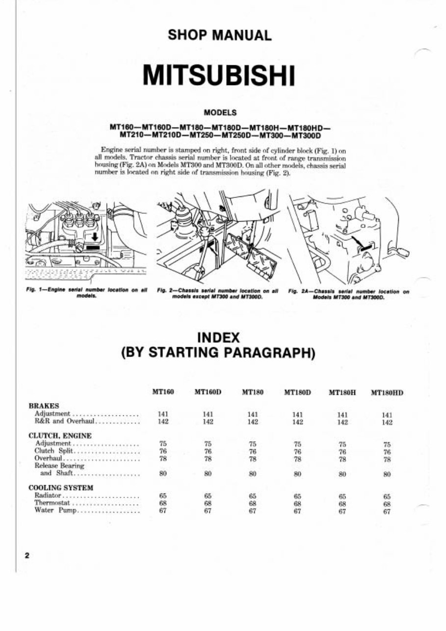
SHOP MANUAL MITSUBISHI MODELS Engine serial number is stamped on right, front side of cylinder block (Fig. 1) on all models. Tractor chassis serial number is located at front of range transmission housing (Fig. 2A) on Models MT300 and MT300D. On all other models, chassis serial number is located on right side of transmission housing (Fig. 2). Fig. 1-Englne serlal number locetlon on ell Fig. 2-Chessls serlal number locatlon on all Fig. 2A-Chessls serial number loce~tio on models. models except MT300 end MT300D. Models MT300 and MT300D. INDEX (BY STARTING PARAGRAPH) BRAKES Adjustment .................. R&R and Overhaul.. .......... CLUTCH, ENGINE Adjustment .................. Clutch Split.. ................ Overhaul. .................... Release Bearing and Shaft.. ................ COOLING SYSTEM Radiator ..................... Thermostat .................. Water Pump.. ...............
INDEX (CONT.) /- DIESEL FUEL SYSTEM I Filter and Bleeding ................... Fuel Shut-Off .................... Solenoid Glow Plugs ................... Governor .................... Injection Pump ............... Injection Pump Camshaft .................. Injector Nozzles ............... DIFFERENTIAL AND BEVEL GEARS Differential .................. 133 133 133 R&R Bevel Gears ............. 132 132 132 ELECTRICAL SYSTEM Alternator and ................... Regulator 69 Fuel Shut-Off Solenoid ................... 72 Safety Start Switch ............ 7 1 Starting Motor ................ 70 ENGINE Assembly. R&R ............... 29 Camshaft and Bearing ......... 39 - Connecting Rods and Bearings ................... 45 Crankshaft and Main Bearings .............. 46 Crankshaft Rear ..................... Oil Seal 47 Cylinder Head ................ 31 Flywheel ..................... 48 Oil Pump and Relief Valve ................ 49 Piston Pins ................... 43 Piston and Rings .............. 42 Piston and Rod Units ...................... 40 Rocker Arms and Shaft ...................... 35 Timing Gear Cover ............ 37 Timing Gears ................. 38 Valve Clearance Adjustment .................. 32 Valve Guides and Springs .................... 34 Valves and Seats .............. 33 Valve Timing ................. 36 FINAL DRIVE ................ 137 137 137 FRONTAXLE SYSTEM Axle Main Member .................... 1 ... 1 Steering Spindles .............. 5 ... 5 ...................... - Tie Rods 4 ... 4 FRONT-WHEEL DRIVE Front Axle ................... ... 8 ... Outer Drive ................... ... 11 ... Tie Rod ...................... ... 10 ...
ENGINE ................ Assembly. R&R .......... Camshaft and Bearing Connecting Rods ................ and Bearings Crankshaft and Main Bearings ................... Crankshaft Rear Oil Seal .................... Cylinder Head ................ Flywheel ..................... Oil Pump and ................. Relief Valve .................... Piston Pins ............... Piston and Rings Piston and Rod Units ....................... Rocker Arms and Shaft ...................... ............. Timing Gear Cover Timing Gears ................. Valve Clearance Adjustment ................. Valve Guides Springs .................... Valves and Seats .............. .................. Valve Timing . FINAL DRIVE ................ FRONT AXLE SYSTEM Axle Main Member ..................... .............. Steering Spindles Tie Rods ...................... FRONT-WHEEL DRIVE Front Axle ................... ................... Outer Drive Tie Rod ....................... HYDRAULIC SYSTEM .................. Control Valve ................ Fluid and Filter ............. Hydraulic Housing ............ Linkage Adjustment Pump ....................... Test and Adjust ............... ............... Trouble-Shooting MANUAL STEERING SYSTEM ...................... Overhaul Remove and Reinstall ................... POWER STEERING SYSTEM ............. Flow Divider Valve Lubrication and Bleeding .................... . Operating Pressure .............. and Relief Valve Pump ....................... Steering Gear ................. ............ POWER TAKE.OFF INDEX (CONT.) MT210 MT210D MT250 MT250D
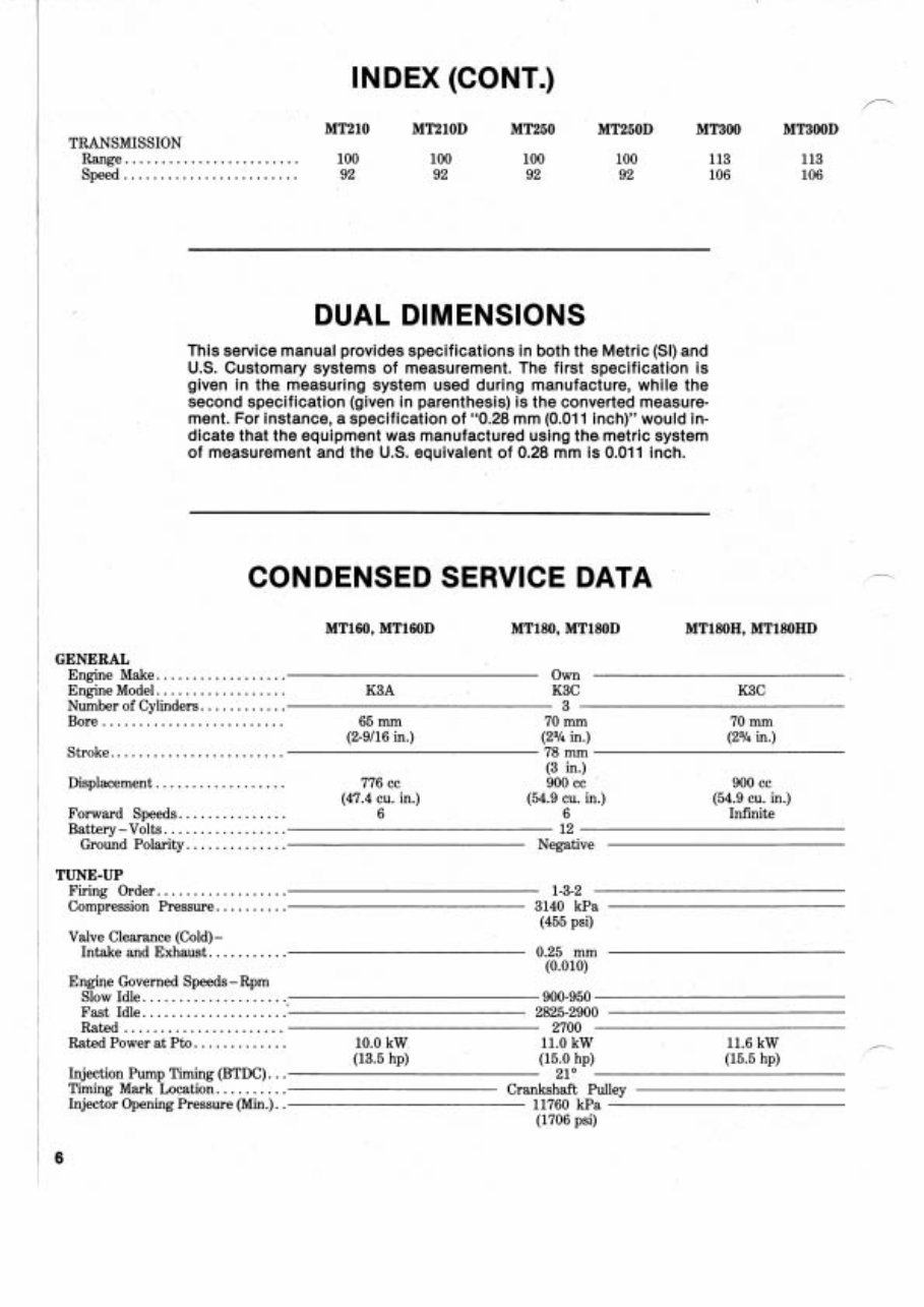
INDEX (CONT.) TRANSMISSION Range ........................ 100 100 100 100 113 Speed ....................... 92 92 92 92 106 DUAL DIMENSIONS This service manual provides specifications in both the Metric (SI) and U.S. Customary systems of measurement. The first specification is given in the measuring system used during manufacture, while the second specification (given in parenthesis) is the converted measure- ment. For instance, a specification of "0.28 mm (0.011 inch)" would in- dicate that the equipment was manufactured using the,metric system of measurement and the U.S. equivalent of 0.28 mm is 0.011 inch. CONDENSED SERVICE DATA GENERAL Engine Make.. ................ Own Engine Model. ................. K3A K3C K3C Number of Cylinders. ........... 3 Bore ......................... 65 mm 70 mm 70 mm (2-9116 in.) (2a/4 in.) (2% in.) Stroke. ....................... 78 mm (3 in.) Displacement .................. 776 cc 900 cc 900 cc ~ (47.4 cu. in.) (54.9 cu. in.) (54.9 cu. in.) , Forward Speeds.. ............. 6 6 Infinite 1 Battery -Volts. ................ 12 , Ground Polarity.. ............ Negative TUNE-UP Firing Order.. ................ 1-3-2 Compression Pressure.. ........ 3140 kPa (455 psi) Valve Clearance (Cold) - Intake and Exhaust. .......... 0.25 mm (0.010) Engine Governed Speeds - Rpm Slow Idle. .................... 900-950 Fast Idle. ................... 2825-2900 Rated ...................... 2700 Rated Power at Pto. ............ 10.0 kW 11.0 kW 11.6 kW (13.5 hp) (15.0 hp) (15.5 hp) Injection Pump Timing (BTDC) ... 21° Timing Mark Location. ......... Crankshaft Pulley Injector Opening Pressure (Min.). . 11760 kPa (1706 psi)
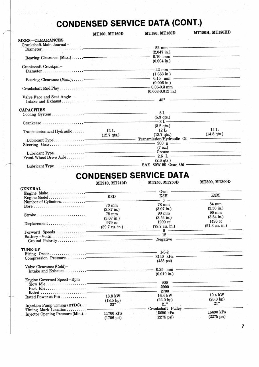
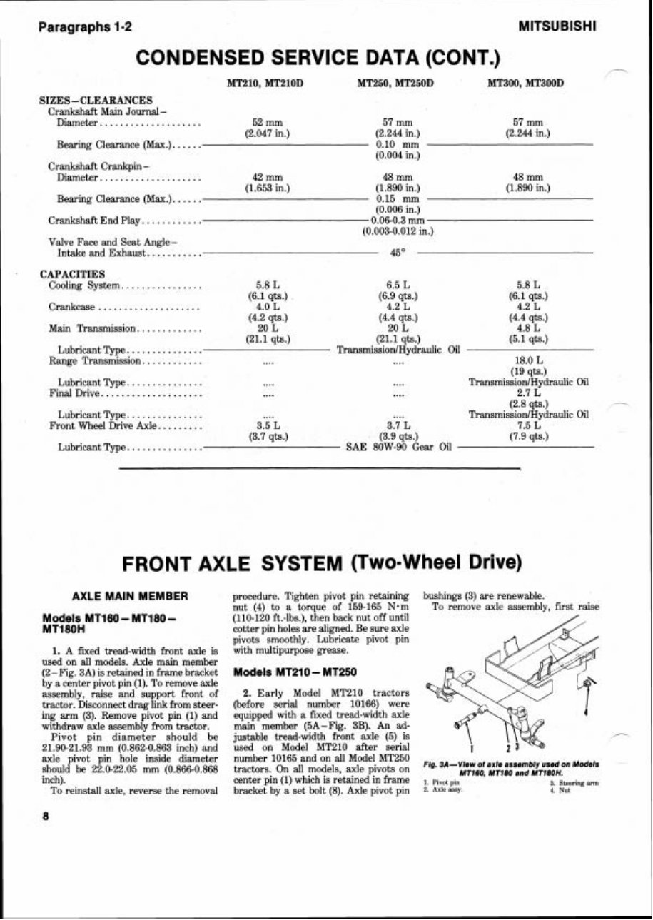
Paragraphs 1-2 CONDENSED SERVICE DATA (CONT.) MT210, MTPlOD MT250, MT250D MT300, MT300D SIZES - CLEARANCES Crankshaft Main Journal - .................... Diameter 52 mm 57 mm 57 mm (2.047 in.) (2.244 in.) (2.244 in.) Bearing Clearance (Max.). ..... 0.10 mm (0.004 in.) Crankshaft Crankpin - .................... Diameter 42 mm 48 mm 48 mm (1.653 in.) (1.890 in.) (1.890 in.) Bearing Clearance (Max.). ..... 0.15 mm (0.006 in.) Crankshaft End Play. ........... 0.06-0.3 mm (0.003-0.012 in.) Valve Face and Seat Angle- Intake and Exhaust. .......... 45" CAPACITIES .............. Cooling System.. 5.8 L 6.5 L 5.8 L (6.1 qts.) (6.9 qts.) (6.1 qts.) .................... Crankcase 4.0 L 4.2 L 4.2 L (4.2 qts.) (4.4 qts.) (4.4 qts.) Main Transmission. ........... 20 L 20 L 4.8 L (21.1 qts.) (21.1 qts.) (5.1 qts.) Lubricant Type. .............. TransmissionlHydraulic Oil Range Transmission. ........... .... .... 18.0 L (19 qts.) .............. Lubricant Type. .... .... TransmissionlHydraulic Oil Final Drive. ................... .... .... 2.7 L (2.8 qts.) -- .............. Lubricant Type. .... .... TransmissionlHydraulic Oil Front Wheel Drive Axle. ........ 3.5 L 3.7 L 7.5 L (3.7 qts.) (3.9 qts.) (7.9 qts.) Lubricant Type. .............. SAE 80W-90 Gear Oil FRONT AXLE SYSTEM (Two=Whee Drive) AXLE MAIN MEMBER procedure. Tighten pivot pin retaining bushings (3) are renewable. nut (4) to a torque of 159-165 N-m To remove axle assembly, first raise Models MT160 - MT180 - (110-120 ft.-lbs.), then back nut off until P MT180H cotter pin holes are aligned. Be sure axle / pivots smoothly. Lubricate pivot pin 1. A fixed tread-width front axle is with multipurpose grease. used on all models. Axle main member (2- Fig. 3A) is retained in frame bracket Models MT210 - MT250 by a center pivot pin (1). To remove axle g assembly, raise and support front of 2. Early Model MT210 tractors tractor. Disconnect drag link from steer- (before serial number 10166) were ing arm (3). Remove pivot pin (1) and equipped with a fixed tread-width axle "i' 4 withdraw axle assembly from tractor. main member (5A-Fig. 3B). An ad- Pivot pin diameter should be justable tread-width front axle (5) is \ 1:- ,- 21.90-21.93 mm (0.862-0.863 inch) and used on Model MT210 after serial 1 axle pivot pin hole inside diameter number 10165 and on all Model MT250 Fig. BA-Ylew axle used Models should be 22.0-22.05 mm (0.866-0.868 tractors. On all models, axle pivots on MT160, MTl8O and MTl8OH. inch). center pin (1) which is retained in frame 1 pivot 3 Steeling arm To reinstall axle, reverse the removal bracket by a set bolt (8). Axle pivot pin 2. Axleassy. 4. NU^
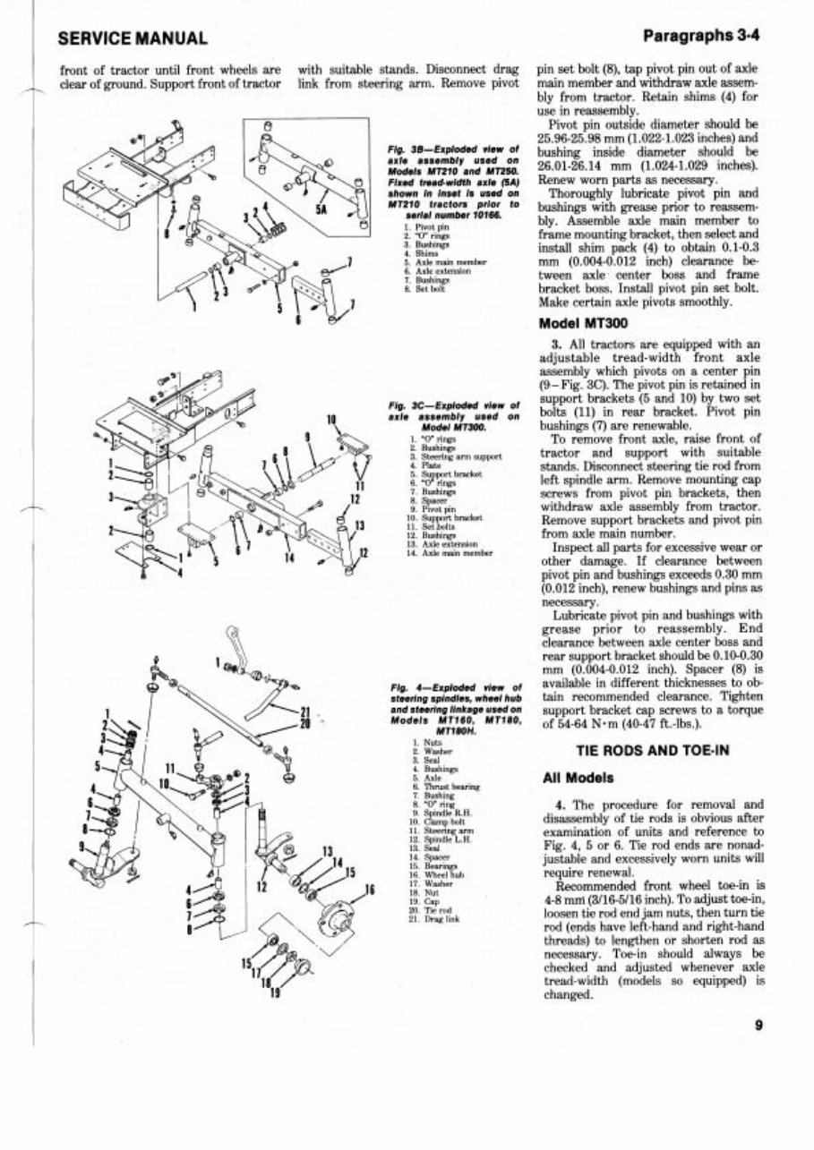
SERVICE MANUAL Paragraphs 3-4 front of tractor until front wheels are with suitable stands. Disconnect drag pin set bolt (8), tap pivot pin out of axle clear of ground. Support front of tractor link from steering arm. Remove pivot main member and withdraw axle assem- bly from tractor. Retain shims (4) for use in reassembly. /r, Pivot pin outside diameter should be 25.96-25.98 mm (1.022-1.023inches) and Fig- 38-Exploded view of bushing inside diameter should be axk assembly used on Models MT210 and MT250. 26.01-26.14 mm (1.024-1.029 inches). Fixed tread-width axle (SA Renew worn parts as necessary. shown in inset is used on Thoroughly lubricate pivot pin and MT210 tractors prior to bushings with grease prior to reassern- serial number 10166. 1 PIVO~ pin bly. Assemble axle main member to 2 -0" nngs frame mounting bracket, then select and 3 Bushings 4 S ~ I install shim pack (4) to obtain 0.1-0.3 5 Axle ma~ member mm (0.004-0.012 inch) clearance be- 6 Axle extension 7 Bushlngs tween axle center boss and frame 8 Set bolt bracket boss. Install pivot pin set bolt. Make certain axle pivots smoothly. Model MT300 3. All tractors are equipped with an adjustable tread-width fronit axle assembly which pivots on a center pin (9 -Fig. 3C). The pivot pin is retained in Fig. 3C-Exploded view of support brackets (5 and 10) by two set axle assembly used on bolts (11) in rear bracket. Pivot pin Model MT300. bushings (7) are renewable. 1 "0 rings To remove front axle, raise front of 2 Bushlngs Steering arm support tractor and support with suitable 4 Plate 5 support bracket stands. Disconnect steering tie rod from 6 "0" rings left spindle arm. Remove mounting cap 7 Bushings 8 Spacer screws from pivot pin brackets, then 9 PIVO~ pln withdraw axle assembly from tractor. 10 Support bracket 11 Set bolts Remove support brackets and pivot pin 12 Bush~ng from axle main number. 13 Axle extension 14 Axle main member Inspect all parts for excessive wear or other damage. If clearance between pivot pin and bushings exceeds (3.30 mm (0.012 inch), renew bushings and pins as necessary. Lubricate pivot pin and bushings with grease prior to reassembly. End clearance between axle center boss and rear support bracket should be 0.10-0.30 mm (0.004-0.012 inch). Spacer (8) is 4-Exploded view of available in different thicknesses to ob- steering spindles, wheel hub tain recommended clearance. Tighten and steerlng linkage used on support bracket cap screws to a torque MT160 MT1801 of 54-64 N-m (40-47 ft.-lbs.). MT18OH. 1 Nuts 2 Washer 3 Seal TIE RODS AND TOE-IN 4 Bushlngs 5 Axle 6 Thrust bearlng All Models 7 Bushing 8 "0" rlng 9 Splndle R.H 4. The procedure for removal and 10 Clamp bolt disassembly of tie rods is obvious after 11 Steer~n arm 12 Sp~ndl L H examination of units and reference to 13 Seal Fig. 4, 5 or 6. Tie rod ends are nonad- 14 Spacer 15 Bearlngs justable and excessively worn units will 16 Wheel hub require renewal. 17 Washer 6 18 NU^ Recommended front wheel toe-in is 19 Cap 4-8 mrri (3116-5116inch). To adjust toe-in, 20 Tie rod 21 Drag llnk loosen tie rod end jam nuts, then turn tie rod (ends have left-hand and right-hand threads) to lengthen or shorten rod as necessary. Toe-in should always be checked and adjusted whenever axle tread-width (models so equipped) is changed.
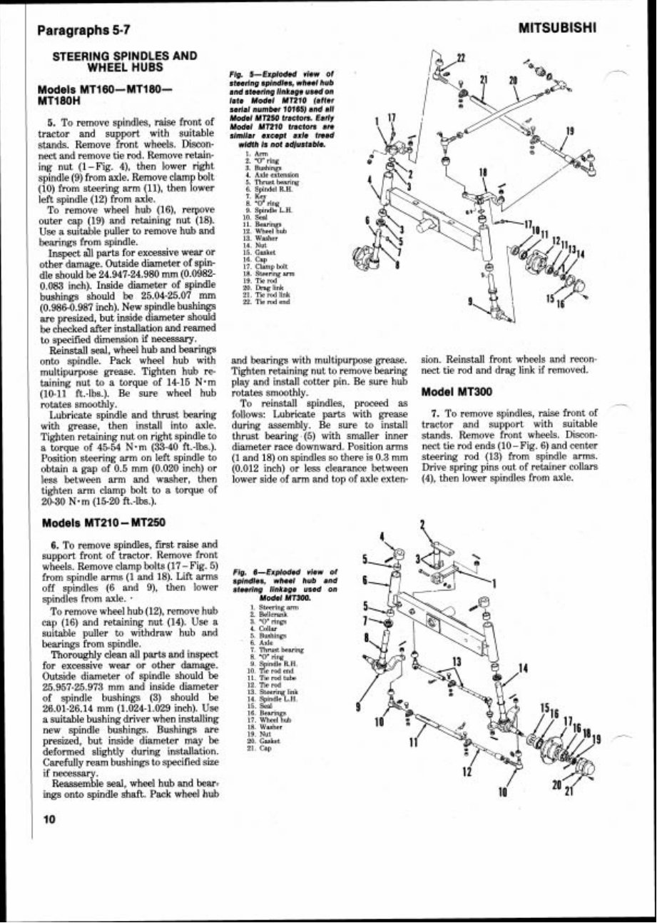
Paragraphs 5-7 STEERING SPINDLES AND WHEEL HUBS Flg. 5-Exploded view of Models MTI 60-MT180- steering spindles, wheel hub and steering llnkage used on MT180H /ate Model MT210 (after serial number 10165) and all 5. To remove spindles, raise front of kz ~~~~fi tractor and support with suitable slmllar except axle tread stands. Remove front wheels. Discon- width Is not adjustable. nect and remove tie rod. Remove retain- I. Arm 2. "0" ring ing nut (1-Fig. 4), then lower right 3. Bushlngs 4. Axle extension spindle (9) from axle. Remove clamp bolt ,, ThNSt bearing (10) from steering arm (ll), then lower 6. Spindel R.H. left spindle (12) from axle. 7. 8. Key "0' ring To remove wheel hub (16), reqove 9. Spindle L.H. outer cap (19) and retaining nut (18). i:: ELnp Use a suitable puller to remove hub and 12. Wheel hub 13. Washer bearings from spindle. 14 NU^ Inspect all parts for excessive wear or 15. Gasket other damage. Outside diameter of spin- i;, EPm 18. Steering arm dle should be 24.947-24.980 mm (0.0982- 0.083 inch). Inside diameter of spindle bushings should be 25.04-25.07 mm 21. Tie rod link (0.986-0.987 inch). New spindle bushings 22 Tie rod end are presized, but inside diameter should be checked after installation and reamed to specified dimension if necessary. Reinstall seal, wheel hub and bearings onto spindle. Pack wheel hub with and bearings with multipurpose grease. sion. Reinstall front wheels and recon- multipurpose grease. Tighten hub re- Tighten retaining nut to remove bearing nect tie rod and drag link if removed. taining nut to a torque of 14-15 N*m play and install cotter pin. Be sure hub (10-11 ft.-lbs.). Be sure wheel hub rotates smoothly. Model MT300 rotates smoothly. To reinstall spindles, proceed as Lubricate spindle and thrust bearing follows: Lubricate parts with grease 7. To remove spindles, raise front of with grease, then install into axle. during assembly. Be sure to install tractor and support with suitable Tighten retaining nut on right spindle to thrust bearing (5) with smaller inner stands. Remove front wheels. Discon- a torque of 45-54 N.m (33-40 ft.-lbs.). diameter race downward. Position arms nect tie rod ends (10-Fig. 6) and center Position steering arm on left spindle to (1 and 18) on spindles so there is 0.3 mm steering rod (13) from spindle arms. obtain a gap of 0.5 mm (0.020 inch) or (0.012 inch) or less clearance between Drive spring pins out of retainer collars less between arm and washer, then lower side of arm and top of axle exten- (4), then lower spindles from axle. tighten arm clamp bolt to a torque of 20-30 N.m (15-20 ft.-lbs.). Models MT210 - MT250 6. To remove spindles, first raise and support front of tractor. Remove front wheels. Remove clamp bolts (17-Fig. 5) from spindle arms (1 and 18). Lift arms ~ $ , d ~ < E ,,$w 6 off spindles (6 and 9), then bwer steerlng linkage used on spindles from axle. . Model MT300. To remove wheel hub (12), remove hub 1 Steering arm 2 Bellcrank 3 "0 nngs cap (16) and retaining nut (14). Use a collar suitable puller to withdraw hub and 5 Bushings bearings from spindle. 6 Axle Thoroughly clean all parts and inspect 7. Thrust bearlng 8 "0 ring 9 Spindle R.H for excessive wear or other damage. ,, ,e rod end Outside diameter of spindle should be 11 rod tube 12. ne rod 25.957-25.973 mm and inside diameter ,, steering of spindle bushings (3) should be 14. Spindle L.H. 26.01-26.14 mm (1.024-1.029 inch). Use :: ELln a suitable bushing driver when installing 11 meel hub new spindle bushings. Bushings are $, :&,She' presized, but inside diameter may be 20. Gasket deformed slightly during installation. 21 Cap Carefully ream bushings to specified size if necessary. Reassemble seal, wheel hub and bear: ings onto spindle shaft. Pack wheel hub
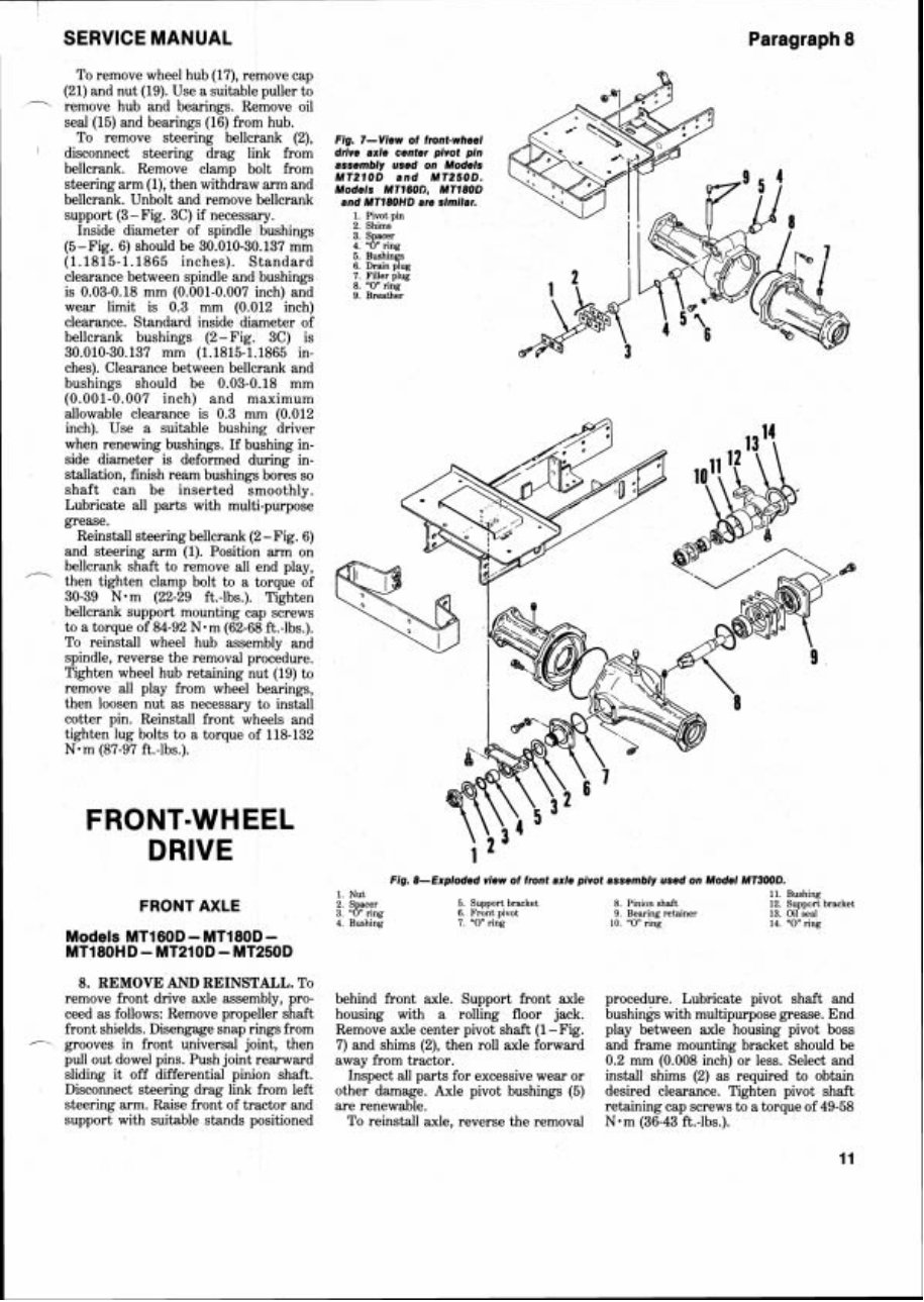
SERVICE MANUAL Paragrlaph 8 To remove wheel hub (17), remove cap (21) and nut (19). Use a suitable puller to remove hub and bearings. Remove oil seal (15) and bearings (16) from hub. To remove steering bellcrank (2), I disconnect steering drag link from bellcrank. Remove clamp bolt from steering arm (I), then withdraw arm and bellcrank. Unbolt and remove bellcrank support (3 - Fig. 3C) if necessary. Inside diameter of spindle bushings (5-Fig. 6) should be 30.010-30.137 mm (1.1815-1.1865 inches). Standard clearance between spindle and bushings is 0.03-0.18 mm (0.001-0.007 inch) and wear limit is 0.3 mm (0.012 inch) clearance. Standard inside diameter of bellcrank bushings (2-Fig. 3C) is 30.010-30.137 mm (1.1815-1.1865 in- ches). Clearance between bellcrank and bushings should be 0.03-0.18 mm (0.001-0.007 inch) and maximum allowable clearance is 0.3 mm (0.012 inch). Use a suitable bushing driver when renewing bushings. If bushing in- side diameter is deformed during in- stallation, finish ream bushings bores so shaft can be inserted smoothly. Lubricate all parts with multi-purpose grease. Reinstall steering bellcrank (2 -Fig. 6) and steering arm (1). Position arm on ,- bellcrank shaft to remove all end play, then tighten clamp bolt to a torque of 30-39 N-m (22-29 ft.-lbs.). Tighten bellcrank support mounting cap screws to a torque of 84-92 N-m (62-68 ft.-lbs.). To reinstall wheel hub assembly and spindle, reverse the removal procedure. Tighten wheel hub retaining nut (19) to remove all play from wheel bearings, then loosen nut as necessary to install cotter pin. Reinstall front wheels and tighten lug bolts to a torque of 118-132 N-m (87-97 ft.-lbs.). FRONT-WHEEL DRIVE FRONT AXLE Models MT160D - MT180D - MT180HD - MT210D - MT250D 8. REMOVE AND REINSTALL. To remove front drive axle assembly, pro- ceed as follows: Remove propeller shaft front shields. Disengage snap rings from - grooves in front universal joint, then pull out dowel pins. Push joint rearward sliding it off differential pinion shaft. Disconnect steering drag link from left steering arm. Raise front of tractor and support with suitable stands positioned Flg. 7-View of front-wheel drlve axle center plvot pin assembly used on Models MT210D end MT250D. Models MTlGOD, MTl8OD and MTl8OHD are slmller. 1. Pivot pin 2. Shims 3. Spacer 4. "0" ring 6. Bushings 6. Drain plug 7. Filler plug 8. "0" ring 9. Breather Fig. 8-Exploded view 01 front axle pivot assembly used on Model MT300D. 1 Nut 11 Bushing 2 S acer 5 Support bracket 8 Pinion shaft 12 Suppcrt bracket 3 8' ring 6 Front plvot 9 Bearing retamer 13 Od sell 4 Bushing 7 "0" rlng 10 "0 ring 14 "0" ring behind front axle, Support front axle housing with a rolling floor jack. Remove axle center pivot shaft (1-Fig. 7) and shims (2), then roll axle forward away from tractor. Inspect all parts for excessive wear or other damage. Axle pivot bushings (5) are renewable. To reinstall axle, reverse the removal procedure. Lubricate pivot shaft and bushings with multipurpose grease. End play between axle housing pivot boss and frame mounting bracket should be 0.2 mm (0.008 inch) or less. Select and install shims (2) as required to obtain desired clearance. Tighten pivot! shaft retaining cap screws to a torque of 49-58 N-m (36-43 ft.-lbs.).
This is a comprehensive service repair manual for the Mitsubishi MT160 MT160D Tractor. It contains detailed illustrations, diagrams, wiring schematics, and specifications, along with step-by-step instructions. The manual is printable, allowing you to take the necessary pages with you into the garage or workshop. Whether you are a professional mechanic or a DIY enthusiast, these manuals are an invaluable source of repair and service information for your vehicle.
File Format: .PDF
Language: English
Specifications: Fully Printable, Zoom IN/OUT
Delivery: Instant Download
Requirements: Adobe Reader & Win
Compatible: All Versions of Windows & Mac
The Mitsubishi MT160 MT160D Tractor Workshop Service Repair Manual covers:
Detailed substeps that expand on repair procedure information
Notes, cautions, and warnings throughout each chapter
Numbered instructions to guide you through every repair procedure step by step
Bold figure numbers to quickly match illustrations with instructions
Detailed illustrations, drawings, and photos to guide you through every procedure
Numbered table of contents for easy information retrieval
Troubleshooting and electrical service procedures combined with detailed wiring diagrams
Plus, it provides information on the following systems:
Engine Mechanical
Engine Electrical
Emission Control
Fuel System
Clutch System
Manual Transaxle System
Automatic Transaxle System
Driveshaft and Axle
Suspension System
Steering System
Brake System
Body (Interior and Exterior)
Body Electrical System
Heating, Ventilation, Air Conditioning
Lubrication & Maintenance
Differential & Driveline
Vehicle Quick Reference
And much more
Gain instant access to the Mitsubishi MT160 MT160D Tractor Workshop Service Repair Manual for all the essential information you need to maintain and repair your vehicle.
Recently Viewed
5,521,897Happy Clients
2,594,462eManuals
1,120,453Trusted Sellers
15Years in Business
Price:
Actual Price:
Mitsubishi MT160 MT160D Tractor Workshop Service Repair