Ferguson TO30 Tractor Workshop Service Manual for Repair
What's Included?
Lifetime Access
Fast Download Speeds
Online & Offline Access
Access PDF Contents & Bookmarks
Full Search Facility
Print one or all pages of your manual
SHOP MANUAL FERGUSON Models TE20, TO20 and TO30 Tractor serial number stamped on instrument panei name piate. Engine seriai numiier stamped on engine name plate which is located on distributor side of engine. I N D E X (By Starting Paragraph) BELT PUUEY 105A BRAKES Adjustment 100-101 R&R and orexbaul 102 CARBT7RETOR 40 CLUTCH Interchangeability 70 Orerhaul 74 Pedal adiustznent 71 Remove & reinstall 73 COOLING SYSTEM Fan 57 Pump 57 Radiator 55 Thermostat 56 DIFFERENTIAL OTexbaul 91 Remove & reinstall 90 ELECTRICAL Distributor 60-61 Generator 65-66 Generator regulator 65-66 Starting motor 67 ENGINE Assembly R&R 10 Cam followers 15 Camshaft 20 Connecting rods & bearings 24 Crankshaft & bearings 2SA-25B Crankshaft oU seals 18. 26 Cylinder head U Cylinder sleeves 22 ENGINE continued . . . Hywheel R&R , 27 Flywheel timing marks 28 Front oU seal 18 Ignition timing 60-61 Main Bearings 25A Oil filter 30 Oil pump 29 Pistons 22 Piston pins 23 Piston & rod removal 21 Piston rings 22 Rear oil seal 26 Rocker arms 16 Tappets 15 Bming gear cover 18 liming gears 19 Valve guides 13 Valves & valve seats. 12 Valve springs 14 Valve timing 17 FINAL DRIVE Bevel gears .92A 93 Differential overhaul 91 Differential R&R 90 Wheel axle shaft bearings adjust 94 Wheel axle shaft bearings renew 96 Wheel axle shaft & housing R&R 97 Wheel axle shaft oil seal renew 96 Wheel axle shaft R&R 95 FRONT SYSTEM Axle main member 1 Axle pivot pin & bushing 2 Steering gear adjust 4-5 Steering gear overhaul 7 Steering gear R&R 6 Steering spindles 3 GOVERNOR Adjustment, minor 50 Adjustment, major 50A R&R and overhaul 51 HYDRAULIC SYSTEM Adjustment 120-123 InterchangeabiUty 119-119A Lift cover 129-130C Pump 125-128G Trouble shooting 124A.124D Work cyUnder 130A IGNITION SYSTEM XE20 80 TO20-TO30 01 POWER TAKE-OFF UO-IU REAR AXLE Bearing, renewal 96 Lubrication 96 Seals, renewal 98 Shaft. R&R 95 STEERING GEAR Adjustment 4-5 Overhaul 7 Remove & reinstaU 6 TRANSMISSION Assembly R&R 81 Basic procedure 80-80D Bevel pinion , 92A Clutch shaft 82 Countershaft 85 InterchangeabiUty 79 Main drive gear & shaft 82 Main shaft 84 Reverse gear 86 Shifter raiU and forks 83A
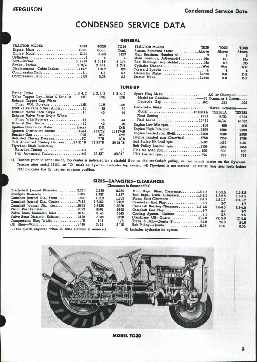
FERGUSON Condensed Service Data CONDENSED SERVICE DATA TRACTOR MODEL TE20 TO20 Engine Make Cont. Cont. Engine Model Z120 Z120 Cylinders 4 4 Bore—Inches 3 3/16 3 3/16 Stroke—Inches 3 3/4 3 3/4 Displacement—Cubic Inches 119.7 119.7 Compression Ratio 6.1 6.1 Compression Ratio 5.08 5.08 Firing Order 1. 3. 4, 2 1, 3. 4. 2 Valve Tappet Gap—Inlet & Exhaust 13H 13H Exhaust Tappet Gap When Fitted With Rotators 13H 13H Inl^t Valve Face & Seat Angle 45 45 Exhaust Valve Face Angle 45 45 Exhaust Valve Face Angle When Fitted With Rotators 44 44 Exhaust Seat Angle 45 45 Ignition Distributor Make Lucas D-R Ignition DUtributor Model D3A4 1111722 Breaker Gap 015 .022 Retarded Timing Degrees TC 7*'B Full Advanced Timing Degrees 27-31**B 29-33'*B Flywheel Mark Indicating:, Retarded Timing (1) 7* Full Advanced Timing. (4) 29-33° GENERAL TO3a TRACTOR MODEL TE20 TO20 TO30 Cont. Pistons Removed From: Above Above Above Z129 Main Bearings. Number of ,3 3 3 4 Main Bearings. Adjustable? No No No 3 1/4 Rod Bearings. Adjustable? No No No 3 7/8 CyUnder Sleeves Wet Wet Wet 129 Forward Speeds 4 4 4 6.5 Generator Make Lucas D-R D-R 8.0 Starter Make Lucas D-R D^B TUNE-UP 1,3.4,2 13H 13H 30 44 44 45 D-R 1111740 .022 6'B 30-34''B 6' 30-34* Spark Plug Make ^AC or Chan Model for Gasoline 66 Comm. or 8 Comm.- Electrode Gap 025 .025 .025 Carburetor Make Marvel Schebler Model TSX361A TSX361A TSX458 Hoat Setting 9/32 9/32 9/32 Fuel Level 15/32 15/32 15/32 Engine Low Idle rpm 400 400 400 Engine High Idle rpm 2200 2200 2200 Engine Loaded rpm (Belt) 2000 2000 2000 Engine Loaded rpm (Drawbar) 1750 1750 1750 Belt Pulley No Load rpm 1493 1493 1493 Belt PuUey Loaded rpm 1358 1358 1358 PTO No Load rpm 800 800 800 PTO Loaded rpm .727 727 727 (1) Tractors prior to serial 36152, top center is indicated by a straight Une on the crankshaft puUey, or two punch marks on the flywheeL Tractors after serial 36151. an "O" mark on flywheel indicates top center. (4) Rywheel is not marked; 12 starter ring gear teeth before TDC indicates the 29 degree advance position. Crankshaft Journal Diameter 2.250 Crankpin Diameter 1.937 Camshaft Journal Dia., Front 1.809 Camshaft Journal Dia., Center 1.7462 Camshaft Journal Dia., Rear 1.6838 Piston Pin Diameter 8592 Valve Stem Diameter, Inlet 3145 Valve Stem Diameter, Exhaust 3128 Compression Ring Width 1/8 Oil Ring—Width 3/16 (2) Six quarts required when oil filter element SIZES-CAPACITiES-CLEARANCES (Clearances in thousandths) 2.250 2.250 Main Brgs., IMam. Clearance 1.5-2.5 1.937 1.937 Rod Brgs., Diam. Clearance 15-2 5 1.809 1.809 Piston Skirt Clearance 12-17 1.7462 1.7462 Crankshaft End Play 3.7 1,6838 1.6838 Camshaft Bearing Clearance 25^ 5 .8592 .8592 Camshaft End Play 3.7 .3145 .3145 CooUng System—Gallons 2 5 .3128 .3128 Crankcase Oil—Quarts (2) 5.0 1/8 1/8 Trans. & Diff.—QttaTts C3) 24 0 3/16 3/16 Belt Pulley—Quarts 0.35 is renewed. (3) Includes hydrauUc Uft system. 1.5-2.5 1.5-2.5 1.2-1.7 3-7 2.5-4.5 3.7 2.5 (2)5.0 24.0 0.35 1.5-23 1.5-2.5 1.2-1.7 3.7 2.5-4.5 3-7 2.5 (2)5.0 24.0 0.35 MODEL TO30
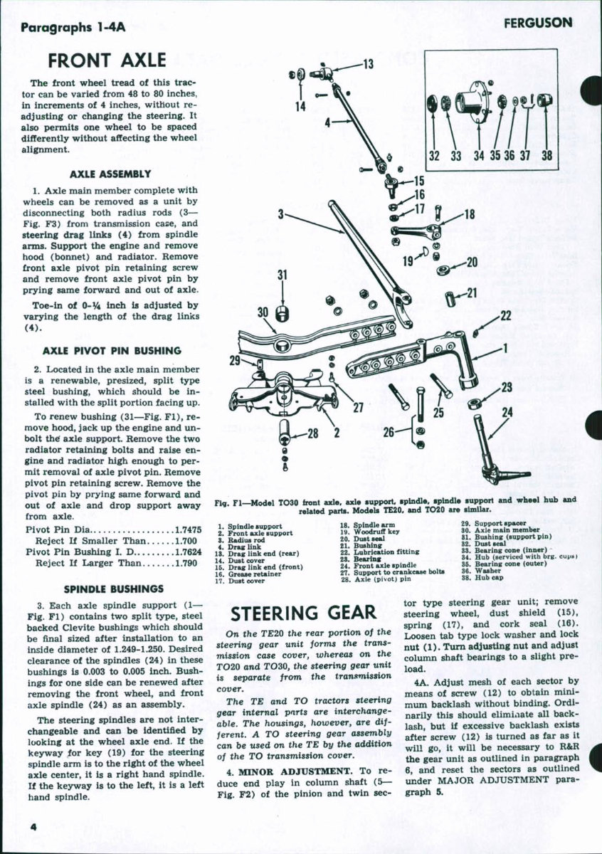
Paragraphs 1-4A FERGUSON FRONT AXLE The front wheel tread of this trac- tor can be varied from 48 to 80 inches, in increments of 4 inches, without re- adjusting or changing the steering. It also permits one wheel to be spaced differently without affecting the wheel alignment. AXLE ASSEMBLY 1. Axle main member complete with wheels can be removed as a unit by disconnecting both radius rods (3— Fig. F3) from transmission case, and steering drag links (4) from spindle arms. Support the engine and remove hood (bonnet) and radiator. Remove front axle pivot pin retaining screw and remove front axle pivot pin by prying same forward and out of axle. Toe-in of O~VA inch is adjusted by varying the length of the drag links (4). AXLE PIVOT PIN BUSHING 2. Located in the axle main member is a renewable, presized, split type steel bushing, which should be in- stalled with the split portion facing up. To renew bushing (31—Fig. Fl), re- move hood, jack up the engine and un- bolt th^ axle support. Remove the two radiator retaining bolts and raise en- gine and radiator high enough to per- mit removal of axle pivot pin. Remove pivot pin retaining screw. Remove the pivot pin by prying same forward and out of axle and drop support away from axle. Pivot Pin Dia 1.7475 Reject If Smaller Than 1.700 Pivot Pin Bushing I. D 1.7624 Reject If Larger Than 1.790 SPINDLE BUSHINGS 3. Each axle spindle support (1— Fig. Fl) contains two split tjrpe, steel backed Clevite bushings which should be final sized after installation to an inside diameter of 1.249-1.250. Desired clearance of the spindles (24) in these bushings is 0.003 to 0.005 inch. Bush- ings for one side can be renewed after removing the front wheel, and front axle spindle (24) as an assembly. The steering spindles are not inter- changeable and can be identified by looking at the wheel axle end. If the keyway for key (19) for the steering spindle arm is to the right of the wheel axle center, it is a right hand spindle. If the keyway is to the left, it is a left hand spindle. 32 33 34 35 36 37 38 Fig. Fl—Model TO30 front axle, axle support spindle, spindle suppoH and wheel hub and related parts. Models TE20, and TO20 are simiUr. 1. Spindle support 2. Front axle support 3. Radius rod 4. Drag link 13. Drag link end (rear) 14. Dust cover 15. Drag link end (front) 16. Grease retainer 17. Dusteover 18. Spindle arm 19. Woodruff key 20. DuBtseal 21. Bushing 22. Lubrication fitting 28. Bearins 24. Front axle spindle 27. Support to crankcase bolts 28. Axle (pivot) pin 29. Support spacer 80. Axle main member 81. Biubing (support pin) 82. Dust seal 88. Bearing cone (inner) 34. Hub (serviced with brg. 36. Bearing cone (outer) 36. Washer 38. Hub cap STEERING GEAR On the TE20 the rear portion of the steering gear unit forms the trans- mission case cover, whereas on the TO20 and TO30, the steering gear unit is separate from the transmission cover. The TE and TO tractors steering gear internal parts are interchange- able. The housings, however, are dif- ferent, A TO steering gear assembly can be used on the TE by the addition of the TO transmission cover, 4. MINOR ADJUSTMENT. To re- duce end play in column shaft (5— Fig. F2) of the pinion and twin sec- tor type steering gear unit; remove steering wheel, dust shield (15), spring (17), and cork seal (16). Loosen tab type lock washer and lock nut (1). Turn adjusting nut and adjust column shaft bearings to a slight pre- load. 4A. Adjust mesh of each sector by means of screw (12) to obtain mini- mum backlash without binding. Ordi- narily this should eliminate all back- lash, but if excessive backlash exists after screw (12) is turned as far as it will go, it will be necessary to R&R the gear unit as outlined in paragraph 6, and reset the sectors as outlined under MAJOR ADJUSTMENT para- graph 5.
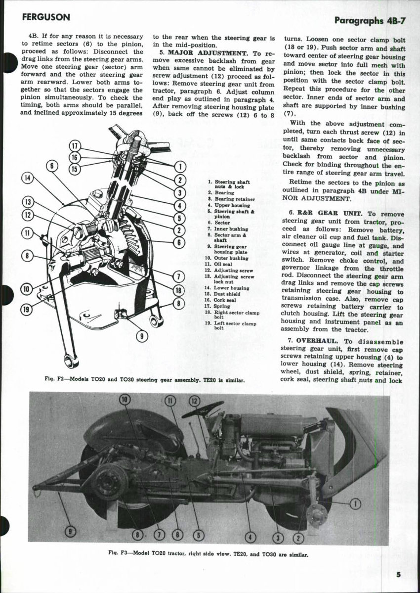
FERGUSON 4B. If for any reason it is necessary to retime sectors (6) to the pinion, proceed as follows: Disconnect the drag links from the steering gear arms. Move one steering gear (sector) arm forward and the other steering gear arm rearward. Liower both arms to- gether so that the sectors engage the pinion simultaneously. To check the timing, both arms should be parallel, and inclined approximately 15 degrees Paragraphs 4B-7 to the rear when the steering gear is in the mid-position. 5. MAJOR ADJUSTMENT. To re- move excessive backlash from gear when same cannot be eliminated by screw adjustment (12) proceed as fol- lows; Remove steering gear unit from tractor, paragraph 6. Adjust column end play as outlined in paragraph 4. After removing steering housing plate (9), back off the screws (12) 6 to 8 1. steering shaft nnts A lock 2. Bearing 8. Bearing retainer 4. Upper housing 6. Steering shaft A pinion 6. Sector 7. Inner bushing 8. Sector arm A sbaft 9. Steering gear bousing plate 10. Outer bushing 11. Oil seal 12. Adjusting screw 18. Adjusting screw lock nut 14. Lower housing Ifi. Dust shield 16. Cork seal 17. Spring 18. Right sector clamp bolt 19. Left sector clamp bolt F2~Models TO20 and TO30 steeilag q%u assembly. TE20 is similar. turns. Loosen one sector clamp bolt (18 or 19). Push sector arm and shaft toward center of steering gear housing and move sector into full mesh with pinion; then lock the sector in this position with the sector clamp bolt. Repeat this procedure for the other sector. Inner ends of sector arm and shaft are supported by inner bushing (7). With the above adjustment com- pleted, turn each thrust screw (12) in until same contacts back face of sec- tor, thereby removing unnecessary backlash from sector and pinion. Check for binding throughout the en- tire range of steering gear arm travel. Retime the sectors to the pinion as outlined in paragraph 4B under MI- NOR ADJUSTMENT. 6. R&R GEAR UNIT. To remove steering gear unit from tractor, pro- ceed as follows: Remove battery, air cleaner oil cup and fuel tank. Dis- connect oil gauge line at gauge, and wires at generator, coil and starter switch. Remove choke control, and governor linkage from the throttle rod. Disconnect the steering gear arm drag links and remove the cap screws retaining steering gear housing to transmission case. Also, remove cap screws retaining battery carrier to clutch housing. Lift the steering gear housing and instrument panel as an assembly from the tractor. 7. OVERHAUL. To disassemble steering gear unit, first remove cap screws retaining upper housing (4) to lower housing (14). Remove steering wheel, dust shield, spring, retainer, cork seal, steering shaft nuts and lock Fig. F3—Model TO20 tractor, right side view. TE20, and TO30 are similar.
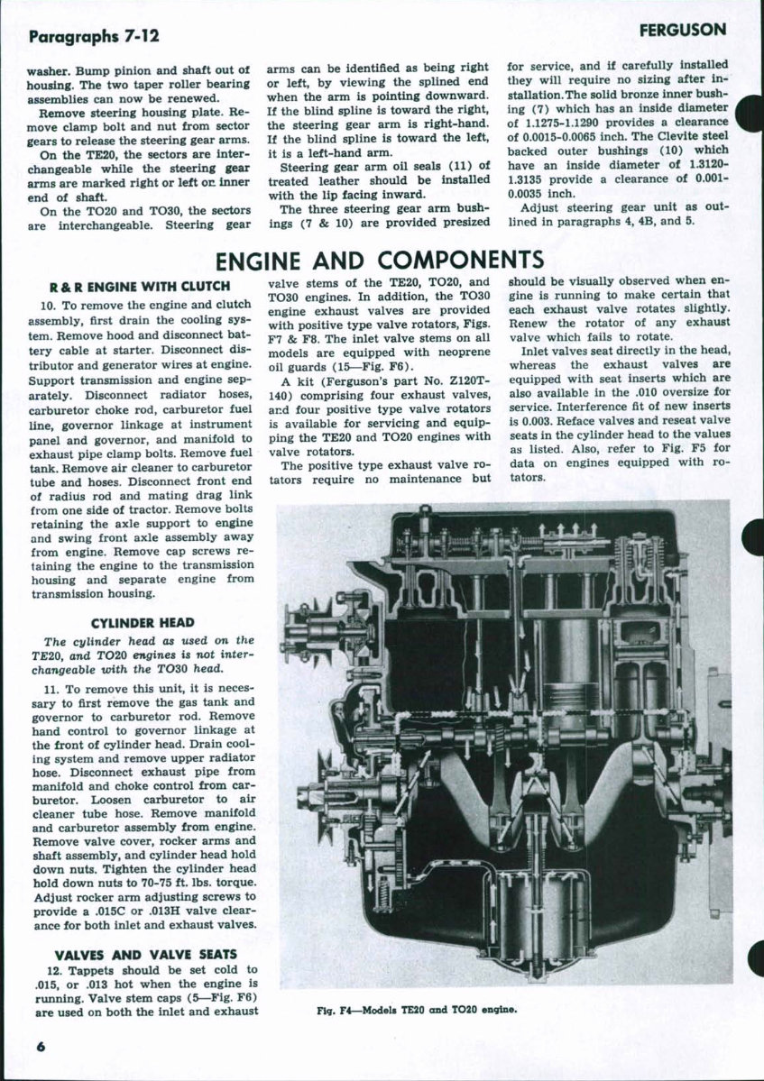
Paragraphs 7-12 washer. Bump pinion and shaft out of housing. The two taper roller bearing assemblies can now be renewed. Remove steering housing plate. Re- move clamp bolt and nut from sector gears to release the steering gear arms. On the TE20, the sectors are inter- changeable while the steering gear arms are marked right or left on inner end of shaft. On the TO20 and TO30, the sectors are interchangeable. Steering gear arms can be identified as being right or left, by viewing the splined end when the arm is pointing downward. If the blind spline is toward the right, the steering gear arm is right-hand. If the blind spline is toward the left, it is a left-hand arm. Steering gear arm oil seals (11) of treated leather should be installed with the lip facing inward. The three steering gear arm bush- ings (7 & 10) are provided presized FERGUSON for service, and if carefully installed they will require no sizing after in- stallation. The solid bronze inner bush- ing (7) which has an inside diameter of 1.1275-1.1290 provides a clearance of 0.0015-0.0065 inch. The Clevite steel backed outer bushings (10) which have an inside diameter of 1.3120- 1.3135 provide a clearance of 0.001- 0.0035 inch. Adjust steering gear unit as out- lined in paragraphs 4, 4B, and 5. ENGINE AND COMPONENTS R&R ENGINE WITH CLUTCH 10. To remove the engine and clutch assembly, first drain the cooling sys- tem. Remove hood and disconnect bat- tery cable at starter. Disconnect dis- tributor and generator wires at engine. Support transmission and engine sep- arately. Disconnect radiator hoses, carburetor choke rod, carburetor fuel line, governor linkage at instrument panel and governor, and manifold to exhaust pipe clamp bolts. Remove fuel tank. Remove air cleaner to carburetor tube and hoses. Disconnect front end of radius rod and mating drag link from one side of tractor. Remove bolts retaining the axle support to engine and swing front axle assembly away from engine. Remove cap screws re- taining the engine to the transmission housing and separate engine from transmission housing. CYLINDER HEAD The cylinder head as used on the TE20, and TO20 engines is not inter- changeable with the TOZO head, 11. To remove this unit, it is neces- sary to first remove the gas tank and governor to carburetor rod. Remove hand control to governor linkage at the front of cylinder head. Drain cool- ing system and remove upper radiator hose. Disconnect exhaust pipe from manifold and choke control from car- buretor. Loosen carburetor to air cleaner tube hose. Remove manifold and carburetor assembly from engine. Remove valve cover, rocker arms and shaft assembly, and cylinder head hold down nuts. Tighten the cylinder head hold down nuts to 70-75 ft. lbs. torque. Adjust rocker arm adjusting screws to provide a .015C or .013H valve clear- ance for both inlet and exhaust valves. VALVES AND VALVE SEATS 12. Tappets should be set cold to .015, or .013 hot when the engine is running. Valve stem caps (5—Fig. F6) are used on both the inlet and exhaust valve stems of the TE20, TO20, and TO30 engines. In addition, the TO30 engine exhaust valves are provided with positive type valve rotators. Figs. F7 & F8. The inlet valve stems on all models are equipped with neoprene oil guards (15—Fig. F6). A kit (Ferguson's part No. Z120T- 140) comprising four exhaust valves, and four positive type valve rotators is available for servicing and equip- ping the TE20 and TO20 engines with valve rotators. The positive type exhaust valve ro- tators require no maintenance but should be visually observed when en- gine is running to make certain that each exhaust valve rotates slightly. Renew the rotator of any exhaust valve which fails to rotate. Inlet valves seat directly in the head, whereas the exhaust valves are equipped with seat inserts which are also available in the .010 oversize for service. Interference fit of new inserts is 0.003. Reface valves and reseat valve seats in the cylinder head to the values as listed. Also, refer to Fig. F5 for data on engines equipped with ro- tators. Fig. F4—Models TE20 and TO20 engine,
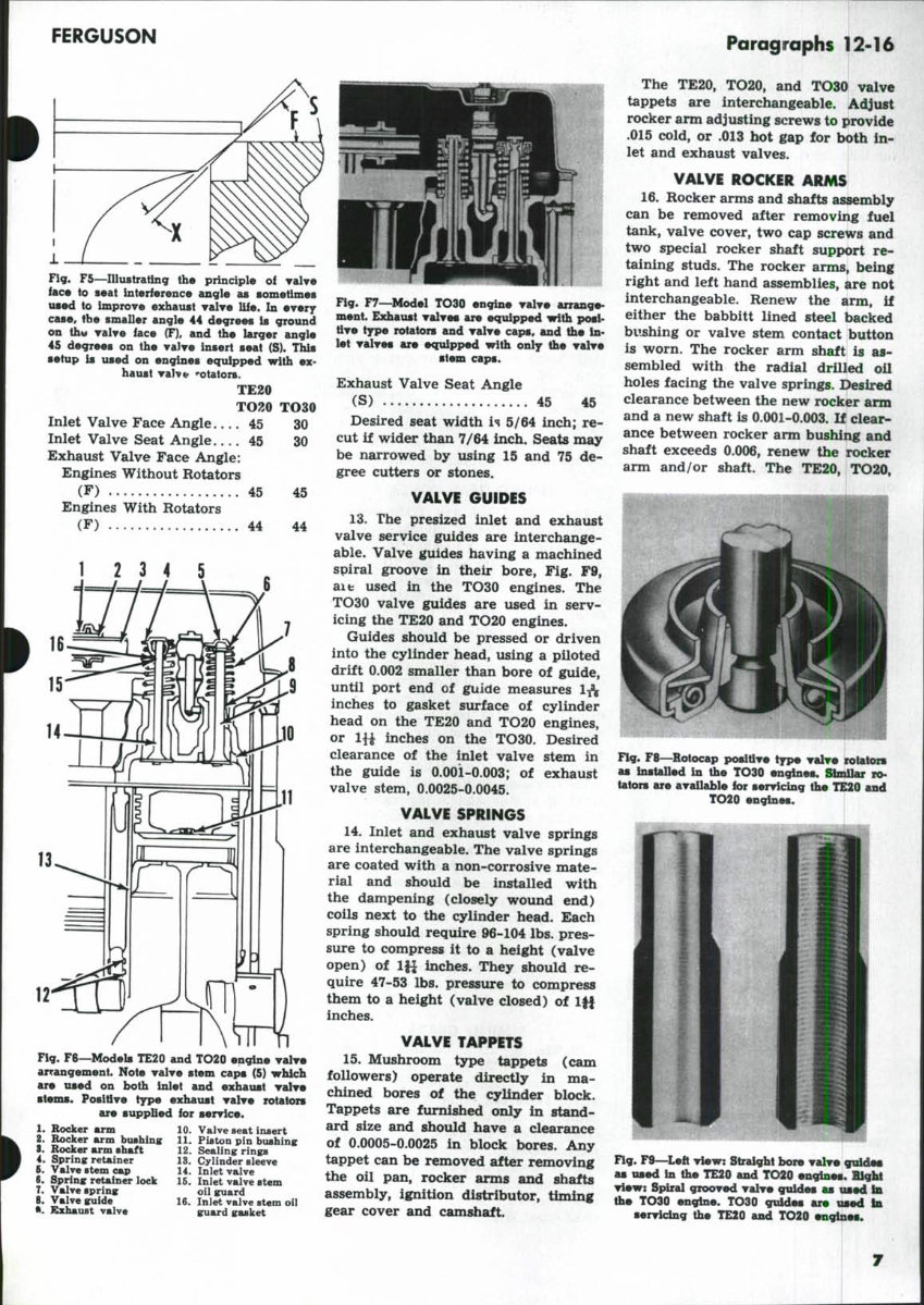
FERGUSON Paragraphs 12-16 Fig. F5—niustratlng the principle of Talve face to seat Interference angle as sometimes used to improve exhaust ralTe life. In everf case« the smaller angle 44 degrees is ground on thtf TalTe face (F), and the larger angle 45 degrees on the vaWe insert seat (S). This setup is used on engines equipped with ex- haust TaW^ ••otators. TE20 TO30 Inlet Valve Face Angle 45 30 Inlet Valve Seat Angle 45 30 Exhaust Valve Face Angle: Engines Without Rotators (F) 45 45 Engines With Rotators (F) 44 44 1 2 3 4 5 Fig. F8—Models TE20 and TO20 engine valve arrangement. Note valve stem caps (5) which are used on both inlet and exhaust valve stems. Positive type exhaust valve rotators are supplied for service. 1. Rocker arm 2. Bocker arm bushing S. Rocker arm sbaft 4. Spring reUiner t. ValT« stem cap 8. Spring retainer lock 7. Valve spring 5. Valve guide •. Kxhaust valve 10. Valve seat insert 11. Piston pin bushing 12. Sealing rini^ 15. Cylinder sleeve 14. Inlet valve 16. Inlet valve stem oil guard 16. Inlet valve stem oil guard gasket Fig. F7—^Model TO30 engine valve arrange- ment. Exhaust valves are equipped with posi- tive type rotators and valve caps, and the In- let valves are equipped with only the valve stem caps. Exhaust Valve Seat Angle (S) 45 45 Desired seat width is 5/64 inch; re- cut if wider than 7/64 inch. Seats may be narrowed by using 15 and 75 de- gree cutters or stones. VALVE GUIDES 13. The presized inlet and exhaust valve service guides are interchange- able. Valve guides having a machined spiral groove in their bore. Fig. F9, aifc used in the TO30 engines. The TO30 valve guides are used in serv- icing the TE20 and TO20 engines. Guides should be pressed or driven into the cylinder head, using a piloted drift 0.002 smaller than bore of guide, until port end of guide measures lA inches to gasket surface of cylinder head on the TE20 and TO20 engines, or m inches on the TO30. Desired clearance of the inlet valve stem in the guide is 0.001-0.003; of exhaust valve stem, 0.0025-0.0045. VALVE SPRINGS 14. Inlet and exhaust valve springs are interchangeable. The valve springs are coated with a non-corrosive mate- rial and should be installed with the dampening (closely wound end) coils next to the cylinder head. Each spring should require 96-104 lbs. pres- sure to compress it to a height (valve open) of lfi inches. They should re- quire 47-53 lbs. pressure to compress them to a height (valve closed) of Iff inches. VALVE TAPPETS 15. Mushroom type tappets (cam followers) operate directly in ma- chined bores of the cylinder block. Tappets are furnished only in stand- ard size and should have a clearance of 0.0005-0.0025 in block bores. Any tappet can be removed after removing the oil pan, rocker arms and shafts assembly, ignition distributor, timing gear cover and camshaft. The TE20, TO20, and TO30 valve tappets are interchangeable. Adjust rocker arm adjusting screws to provide .015 cold, or .013 hot gap for both in- let and exhaust valves. i VALVE ROCKER ARMS 16. Rocker arms and shafts assembly can be removed after removing fuel tank, valve cover, two cap screws and two special rocker shaft support re- taining studs. The rocker arms, being right and left hand assemblies, are not interchangeable. Renew the arm, if either the babbitt lined steel backed bushing or valve stem contact button is worn. The rocker arm shaft is as- sembled with the radial drilled oil holes facing the valve springs. Desired clearance between the new rocker arm and a new shaft is 0.001-0.003. If clear- ance between rocker arm bushing and shaft exceeds 0.006, renew the rocker arm and/or shaft. The TE20, TO20, Fig. F8—Rotocap po^tlve type valve rotators as installed in ihe TO30 engines. Similar vo- talors are available for servicing the TE20 and TO20 engines. Fig. F9—^Left view: Straight bore valve guides as used In the TE20 and TO20 engines. Bight view: Spiral grooved valve guides as used In the TO30 engine. TO30 guides are used In servicing the TE20 and TO20 engines.
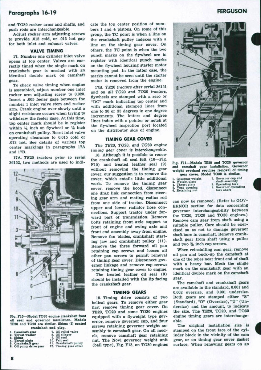
Paragraphs 16-19 and TO30 rocker arms and shafts, and push rods are interchangeable. Adjust rocker arm adjusting screws to provide .015 cold, or .013 hot gap for both inlet and exhaust valves. VALVE TIMING 17. Number one cylinder inlet valve opens at top center. Valves are cor- rectly timed when the single mark on crankshaft gear is meshed with an identical double mark on camshaft gear. To check valve timing when engine is assembled, adjust number one inlet rocker arm adjusting screw to 0.020. Insert a .005 feeler gage between the number 1 inlet valve stem and rocker arm. Crank engine over slowly until a slight resistance occurs when trying to withdraw the feeler gage. At this time, top center mark should be in register within y\ inch on fiywheel or y% inch on crankshaft pulley. Reset inlet valve operating clearance to 0.015 cold or .013 hot. See details of various top center markings in paragraphs 17A and 17B. 17A. T£20 tractors prior to serial 36152, two methods are used to indi- r FERGUSON Fig. FIO—Model TO30 engine crankshaft front oil seal and governor installation. Models TE20 and TO20 are sinUlar. Shims (3) control crankshaft end play. 1. Camshaft g«Mr 7. Oil relief valve 2. Thrust washer 8. Oil slinger 8. Shims 9. Oil seal 4. Thrust plato 10. Felt seal 5. Crankshaft gear 11. Crankshaft pulley 8. Oil pump p 12. Timing gear cover cate the top center position of num- bers 1 and 4 pistons. On some of this group, the TC point is when a line on the crankshaft pulley indexes with a line on the timing gear cover. On others, the TC point is when the two punch marks on the fiywheel are in register with identical punch marks on the flywheel housing starter motor mounting pad. In the latter case, the marks cannot be seen until the starter motor is removed from the engine. 17B. TE20 tractors after serial 36151 and on all TO20 and TO30 tractors, flywheels are stamped with a zero or "DC" mark indicating top center and v/ith additional stamped lines from one to 30 or 35 degrees in one degree increments. The letters and degree lines index with a pointer or notch at the flywheel inspection port located on the distributor side of engine. TIMING GEAR COVER The TJE20, rO20, and TO30 engine timing gear co^er is interchangeable, 18. Although it is possible to renew the crankshaft oil seal felt (10—Fig. FIO) and treated leather seal (9) without removing the timing gear cover, our suggestion is to remove the cover, which entails little additional work. To remove the timing gear cover, remove the hood, disconnect one drag link connection from steer- ing gear arm and mating radius rod from one side of tractor. Disconnect upper and lower radiator hose con- nections. Support tractor under for- ward part of transmission. Remove bolts retaining front axle support to front of engine and swing axle and front end assembly away from engine. Remove fan blades, crankshaft start- ing jaw and crankshaft pulley (11). Remove the three forward oil pan retaining cap screws and loosen all other pan screws to permit removal of timing gear cover. Disconnect gov- ernor linkage and remove cap screws retaining timing gear cover to engine. The treated leather oil seal (9) should be installed with the lip facing the crankshaft gear. TIMING GEARS 19. Timing drive consists of two helical gears. To remove either gear first remove timing gear cover. On TE20, TO20 and some TO30 engines equipped with a flyweight type gov- ernor, remove governor cup, and four screws retaining governor weight as- sembly to camshaft gear. On all mod- els, remove camshaft gear retaining nut. The Novi governor weight unit (ball type). Fig. F13, on TO30 engines Flff. Fll—ModeU TE20 and TO20 governor and camshaft gear installation. Governor weight overhaul requires removal of timing gear cover. Model TO30 Is similar. 1. Governor weight 7. Governor cup and 2. Weight plate shaft assembly 4. ThruBt plate 8. Operating fork 5. Vent opening 9. Governor operating 6. Retaining nut fork shaft can now be removed. (Refer to GOV- ERNOR section for data concerning governor interchangeability between the TE20, TO20 and TO30 engines.) Remove cam gear from shaft using a suitable puller. Care should be exer- cised so as not to damage governor shaft bore in camshaft. Remove crank- shaft gear from shaft using a puller and two % inch cap screws. When reinstalling cam gear, remove oil pan and buck-up the camshaft at one of the lobes near front end of shaft with a heavy bar. Mesh the single mark on the crankshaft gear with an identical double mark on the camshaft gear. The camshaft and crankshaft gears are available in the standard, 0.001 and 0.002 oversize, and 0.001 undersize. Both gears are stamped either **S** (Standard), "O" (Oversize), "U" (Un- dersize) and the amount, to indicate the size. The TE20, TO20, and TO30 engine timing gears are interchange- able. The original installation size is stamped on the front face of the cyl- inder block in the vicinity of the cam gear, or on timing gear cover gasket surface. When renewing gears on an s
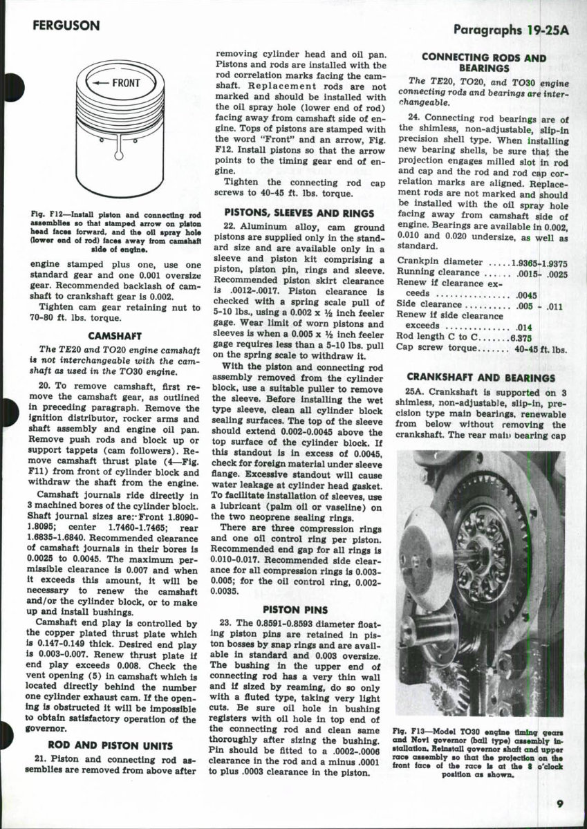
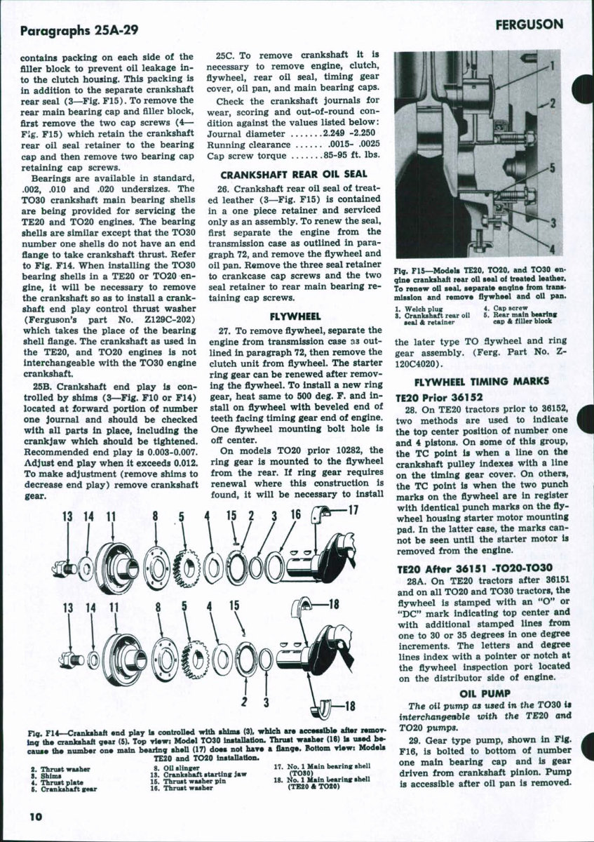
FERGUSON Paragraphs 19-25A Fig. F12—InstaU piston and connecting rod assemblies so that stamped arrow on piston head faces forward, and the oil spray hole (lower end of rod) faces away from camshaft side of engine. engine stamped plus one, use one standard gear and one 0.001 oversize gear. Recommended backlash of cam- shaft to crankshaft gear is 0.002. Tighten cam gear retaining nut to 70-80 ft. lbs. torque. CAMSHAFT The TE20 and TO20 engine camshaft is not interchangeable with the cam- shaft as used in the TO3Q engine, 20. To remove camshaft, first re- move the camshaft gear, as outlined in preceding paragraph. Remove the ignition distributor, rocker arms and shaft assembly and engine oil pan. Remove push rods and block up or support tappets (cam followers). Re- move camshaft thrust plate (4—Fig. Fll) from front of cylinder block and withdraw the shaft from the engine. Camshaft journals ride directly in 3 machined bores of the cylinder block. Shaft journal sizes arerFront 1.8090- 1.8095; center 1.7460-1.7465; rear 1.6835-1.6840. Recommended olearance of camshaft journals in their bores is 0.0025 to 0.0045. The maximum per- missible clearance is 0.007 and when it exceeds this amount, it will be necessary to renew the camshaft and/or the cylinder block, or to make up and install bushings. Camshaft end play is controlled by the copper plated thrust plate which is 0.147-0.149 thick. Desired end play is 0.003-0.007. Renew thrust plate if end play exceeds 0.008. Check the vent opening (5) in camshaft which is located directly behind the number one cylinder exhaust cam. If the open- ing is obstructed it will be impossible to obtain satisfactory operation of the governor. ROD AND PISTON UNITS 21. Pi8ton and connecting rod as- semblies are removed from above after removing cylinder head and oil pan. Pistons and rods are installed with tbe rod correlation marks facing the cam- shaft. Replacement rods are not marked and should be installed with the oil spray hole (lower end of rod) facing away from camshaft side of en- gine. Tops of pistons are stamped with the word "Front" and an arrow. Fig. F12. Install pistons so that the arrow points to the timing gear end of en- gine. Tighten the connecting rod cap screws to 40-45 ft. lbs. torque. PISTONS, SLEEVES AND RINGS 22. Aluminum alloy, cam ground pistons are supplied only in the stand- ard size and are available only in a sleeve and piston kit comprising a piston, piston pin, rings and sleeve. Recommended piston skirt clearance is .0012-.0017. Piston clearance is checked with a spring scale pull of 5-10 lbs., using a 0.002 x % inch feeler gage. Wear limit of worn pistons and sleeves is when a 0.005 x % inch feeler gage requires less than a 5-10 lbs. pull on the spring scale to withdraw it. With the piston and connecting rod assembly removed from the cylinder block, use a suitable puller to remove the sleeve. Before installing the wet type sleeve, clean all cylinder block sealing surfaces. The top of the sleeve should extend 0.002-0.0045 above the top surface of the cylinder block. If this standout is in excess of 0.0045, check for foreign material under sleeve flange. Excessive standout will cause water leakage at cylinder head gasket. To facilitate installation of sleeves, use a lubricant (palm oil or vaseline) on the two neoprene sealing rings. There are three compression rings and one oil control ring per piston. Recommended end gap for all rings is 0.010-0.017. Recommended side clear- ance for all compression rings is 0.003- 0.005; for the oil control ring, 0.002- 0.0035. PISTON PINS 23. The 0.8591-0.8593 diameter float- ing piston pins are retained in pis- ton bosses by snap rings and are avail- able in standard and 0.003 oversize. The bushing in the upper end of connecting rod has a very thin wall and if sized by reaming, do so only with a fluted type, taking very light cuts. Be sure oil hole in bushing registers with oil hole in top end of the connecting rod and clean same thoroughly after sizing the bushing. Pin should be fitted to a .0002-.0006 clearance in the rod and a minus .0001 to plus .0003 clearance in the piston. CONNECTING RODS AND BEARINGS The TE20, TO20, and TOZO engine connecting rods and bearings are inter- changeable, 24. Connecting rod bearings are of the shimless, non-adjustable, slip-in precision shell type. When installing new bearing shells, be sure that the projection engages milled slot in rod and cap and the rod and rod cap cor- relation marks are aligned. Replace- ment rods are not marked and should be installed with the oil spray hole facing away from camshaft side of engine. Bearings are available in 0.002, 0.010 and 0.020 undersize, as well as standard. Crankpin diameter 1.9365-1.9375 Running clearance 0015- .0025 Renew if clearance ex- ceeds 0045 Side clearance 005 - .011 Renew if side clearance exceeds oi4 Rod length C to C. 6.375 Cap screw torque 40-45 ft. lbs. CRANKSHAFT AND BEARINGS 25A. Crankshaft is supported on 3 shimless, non-adjustable, slip-in, pre- cision type main bearings* renewable from below without removing the crankshaft. The rear main bearing cap Fig. F13—Model TO30 engine tSmlng gears cmd Novl governor (boll tn>«) ossembiy In- stallation. ReinstaU governor shaft and upper race assembly so that the projection on the Iront lace of the race Is at the 8 o'clock position as shown*
Paragraphs 25A-29 contains packing on each side of the filler block to prevent oil leakage in- to the clutch housing. This packing is in addition to the separate crankshaft rear seal (3—Fig. F15). To remove the rear main bearing cap and filler block, first remove the two cap screws (4— Fig. F15) which retain the crankshaft rear oil seal retainer to the bearing cap and then remove two bearing cap retaining cap screws. Bearings are available in standard, .002, .010 and .020 undersizes. The TO30 crankshaft main bearing shells are being provided for servicing the TE20 and TO20 engines. The bearing shells are similar except that the TO30 number one shells do not have an end flange to take crankshaft thrust. Refer to Fig. F14. When installing the TO30 bearing shells in a TE20 or TO20 en- gine, it will be necessary to remove the crankshaft so as to install a crank- shaft end play control thrust washer (Ferguson's part No. Z129C-202) which takes the place of the bearing shell flange. The crankshaft as used in the TE20, and TO20 engines is not interchangeable with the TO30 engine crankshaft. 25B. Crankshaft end play is con- trolled by shims (3—Fig. FIO or F14) located at forward portion of number one journal and should be checked with all parts in place, including the crankjaw which should be tightened. Recommended end play is 0.003-0.007. Adjust end play when it exceeds 0.012. To make adjustment (remove shims to decrease end play) remove crankshaft gear. 13 14 11 FERGUSON 25C. To remove crankshaft it is necessary to remove engine, clutch, flywheel, rear oil seal, timing gear cover, oil pan, and main bearing caps. Check the crankshaft journals for wear, scoring and out-of-round con- dition against the values listed below: Journal diameter 2.249 -2.250 Running clearance 0015- .0025 Cap screw torque 85-95 ft. lbs. CRANKSHAFT REAR OIL SEAL 26. Crankshaft rear oil seal of treat- ed leather (3—Fig. F15) is contained in a one piece retainer and serviced only as an assembly. To renew the seal, first separate the engine from the transmission case as outlined in para- graph 72, and remove the flywheel and oil pan. Remove the three seal retainer to crankcase cap screws and the two seal retainer to rear main bearing re- taining cap screws. FLYWHEEL 27. To remove flywheel, separate the engine from transmission case as out- lined in paragraph 72, then remove the clutch unit from fljrwheel. The starter ring gear can be renewed after remov- ing the flywheel. To install a new ring gear, heat same to 500 deg. F. and in- stall on flywheel with beveled end of teeth facing timing gear end of engine. One flywheel mounting bolt hole is off center. On models TO20 prior 10282, the ring gear is mounted to the flywheel from the rear. If ring gear requires renewal where this construction is found, it will be necessary to install 15 2 3 16 Fig. F15—Models TE20. TO20, and TO30 en- gine crankshaft rear oil seal of treated leather. To renew oil seat separate engine from trans- mission and remove flywheel and oil pan. 1. Welch plug 8. Crankshaft rear oil seal & retainer 4. Cap screw G. Rear main hearing cap A filler hloek ng. Fll—Crankshaft end pUy Is cootroUed with shims (3). which are accessible after remov- ing the crankshaft gear (5). Top view: Model TO30 installation. Thrust washer (16) is used be- cause the number one main bearing shell (17) does not have a flange. Bottom view: Modeb TE20 and TO20 installation. 2 Thrust washer 8. Oil slinger IT. No. 1 Main bearing shell 8 SWml la. Crankshaft starting iaw l™80) , , , ^^ 4 TWtplat. IB. Thmst washer pin "' % i ^•feiSf *** •^*" B Cr^£St SMT 16. Thrust wathw (TE20ftTO20) the later type TO flywheel and ring gear assembly. (Ferg. Part No. Z- 120C4020). FLYWHEEL TIMING MARKS TE20 Prior 36152 28. On TE20 tractors prior to 36152, two methods are used to indicate the top center position of number one and 4 pistons. On some of this group, the TC point is when a line on the crankshaft pulley indexes with a line on the timing gear cover. On others, the TC point is when the two punch marks on the flywheel are in register with identical punch marks on the fly- wheel housing starter motor mounting pad. In the latter case, the marks can- not be seen until the starter motor is removed from the engine. TE20 After 36151 .TO20-TO30 28A. On TE20 tractors after 36151 and on all TO20 and TO30 tractors, the flywheel is stamped with an "O" or "DC" mark indicating top center and with additional stamped lines from one to 30 or 35 degrees in one degree increments. The letters and degree lines index with a pointer or notch at the flywheel inspection port located on the distributor side of engine. OIL PUMP The oil pump as used in the TOZO iw interchanpet^ie with the TE20 and TO20 pumps, 29. Gear type pump, shown in Fig. F16, is bolted to bottom of number one main bearing cap and is gear driven from crankshaft pinion. Pump is accessible after oil pan is removed. 10
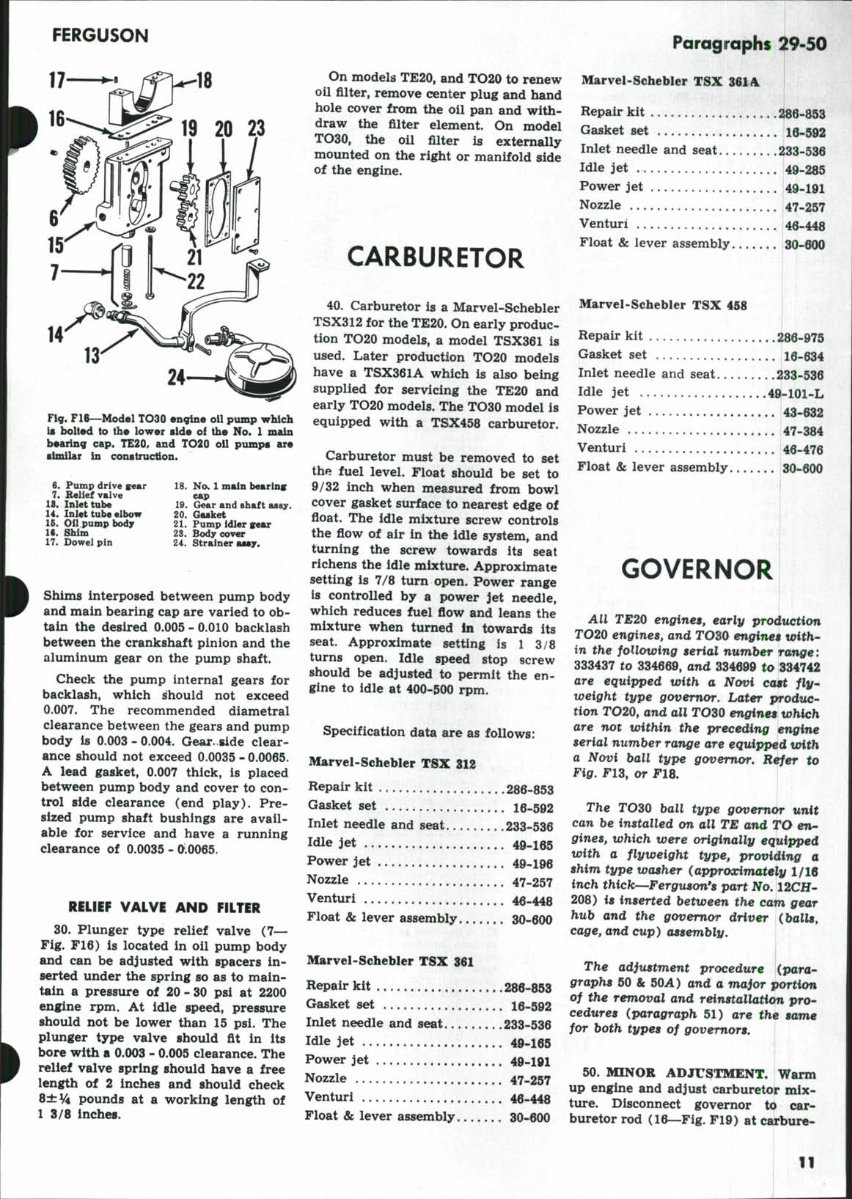
FERGUSON Fig. F16—Model TO30 engine oil pump which Is bolted to the lower side of the No. 1 main bearing cap. TE20, and TO20 oil pumps are similar In construction. 6. Pump drive gear 7. Relief valve 18. Inlet tuh« li. Inlet tuh« elbow 15. Oil pump body 1«. Shim 17. Dowel pin 18. No. 1 main bearing eap 19. Gear and shaft assy. 20. Gasket 21. Pump Idler gtar 23. Bodyoover 24. Strainer assy. Shims interposed between pump body and main bearing cap are varied to ob- tain the desired 0.005 - 0.010 backlash between the crankshaft pinion and the aluminum gear on the pump shaft. Check the pump internal gears for backlash, which Should not exceed 0.007. The recommended diametral clearance between the gears and pump body is 0.003 - 0.004. Gear, side clear- ance should not exceed 0.0035 - 0.0065. A lead gasket, 0.007 thick, is placed between pump body and cover to con- trol side clearance (end play). Pre- sized pump shaft bushings are avail- able for service and have a running clearance of 0.0035 - 0^.0065. RELIEF VALVE AND FILTER 30. Plunger type relief valve (7— Fig. F16) is located in oil pump body and can be adjusted with spacers in- serted under the spring so as to main- tain a pressure of 20 - 30 psi at 2200 engine rpm. At idle speed, pressure should not be lower than 15 psi. The plunger type valve should flt in its bore with a 0.003 - 0.005 clearance. The relief valve spring should have a free length of 2 inches and should check 8±% pounds at a working length of 1 3/8 inches. On models TE20, and TO20 to renew oil fllter, remove center plug and hand hole cover from the oil pan and with- draw the fllter element. On model TO30, the oil filter is externally mounted on the right or manifold side of the engine. CARBURETOR 40. Carburetor is a Marvel-Schebler TSX312 for the TE20. On early produc- tion TO20 models, a model TSX361 is used. Later production TO20 models have a TSX361A which is also being supplied for servicing the TE20 and early TO20 models. The TO30 model is equipped with a TSX458 carburetor. Carburetor must be removed to set the fuel level. Float should be set to 9/32 inch when measured from bowl cover gasket surface to nearest edge of float. The idle mixture screw controls the flow of air in the idle system, and turning the screw towards its seat richens the idle mixture. Approximate setting is 7/8 turn open. Power range is controlled by a power jet needle, which reduces fuel flow and leans the mixture when turned In towards its seat. Approximate setting is 1 3/8 turns open. Idle speed stop screw should be adjusted to permit the en- gine to idle at 400-500 rpm. Specification data are as follows: Marvel-Schebler TSX 312 Repair kit 286-853 Gasket set 16-592 Inlet needle and seat 233-536 Idle jet 49-165 Power jet 49-196 Nozzle 47-257 Venturi 46-448 Float & lever assembly 30-600 Marvel-Schebler TSX 361 Repair kit 286-853 Gasket set 16-592 Inlet needle and seat 233-536 Idle jet 49-165 Power jet 49-191 Nozzle 47-257 Venturi 46-448 Float & lever assembly 30-600 Paragraphs 29-50 Marvel-Schebler XSX 361A Repair kit 286-853 Gasket set 16-592 Inlet needle and seat 233-536 Idle jet 49-285 Power jet 49-191 Nozzle 47-257 Venturi 46-448 Float & lever assembly. 30-600 Marvel-Schebler TSX 458 Repair kit 286-975 Gasket set 16-634 Inlet needle and seat 233-536 Idle jet 49-101-L Power jet 43-632 Nozzle 47-384 Venturi 46-476 Float & lever assembly 30-600 GOVERNOR All TE20 engines, early production TO20 engines, and TOZO engines with- in the following serial number range: 333437 to 334669, and 334699 to 334742 are equipped with a Novi ca$t fly- weight type governor. Later produc- tion TO20, and all TO30 engines which are not within the preceding engine serial number range are equipped with a Novi ball type governor. Refer to Fig. F13, or F18. The TOZO ball type governor unit can be installed on all TE and TO eti- gines, which were originally equipped with a flyweight type, providing a shim type washer (approximately 1/16 inch thick—Ferguson's part No, 12CH- 208) is inserted between the cam gear hub and the governor driver (balls, cage, arui cup) assembly. The adjustment procedure {para- graphs 50 & 50A) and a major portion of the removal and reinstallation pro- cedures (paragraph 51) are the same for both types of governors. 50. MINOR ADJUSTMENT. Warm up engine and adjust carburetor mix- ture. Disconnect governor to car- buretor rod (16—Fig. F19) at carbure- 11
Dive into comprehensive maintenance with the Ferguson TO30 Tractor Workshop Service Manual for Repair. Tailored for the Ferguson TO30 Tractor, this manual delivers extensive data and methodologies required for servicing and repairing your vehicle efficiently. It covers all aspects of the tractor, from routine maintenance to more complex repair tasks.
This manual is packed with special notes, important points, and service data essential for proper maintenance and repairs. It includes precautionary advice and detailed step-by-step procedures for dismantling, overhauling, and reassembling various components of the Ferguson TO30 Tractor.
You will find exploded diagrams, detailed illustrations, and photographs that provide visual step-by-step guides from bumper to bumper. The manual is meticulously detailed, offering a comprehensive look at the tractor to ensure thorough repairs and adjustments.
Each procedure in the manual references specific service tool numbers, and accompanying illustrations depict these tools to facilitate accurate and safe repairs. The manual is designed for ease of use, available in PDF format, which allows for quick navigation and printing capabilities, ensuring you can bring the right instructions right into the workshop.
This manual is essential for professional mechanics and DIY enthusiasts alike. It includes torque specifications and service tool data necessary for correct reassembly, ensuring the tractor operates safely after maintenance. Whether you are troubleshooting a problem or conducting full-scale repairs, this manual provides all the information necessary to meet the factory standards.
All procedures are supported with safety warnings and notes to prevent injury and ensure proper handling of the tractor. The Ferguson TO30 Tractor Workshop Service Manual is a vital resource, ensuring every repair is performed accurately, enhancing the tractor’s longevity and reliability. It’s more than just a manual; it’s an essential companion for maintaining your tractor in optimum condition.
Recently Viewed
5,521,897Happy Clients
2,594,462eManuals
1,120,453Trusted Sellers
15Years in Business
Price:
Actual Price:
Ferguson TO30 Tractor Workshop Service Manual for Repair