

Massey Ferguson Service MF 3300 Series MF-3315, MF-3325, MF-3330, MF-3340, MF-3350, MF-3355 Manual Complete Tractor Workshop Man
What's Included?
Fast Download Speeds
Online & Offline Access
Access PDF Contents & Bookmarks
Full Search Facility
Print one or all pages of your manual
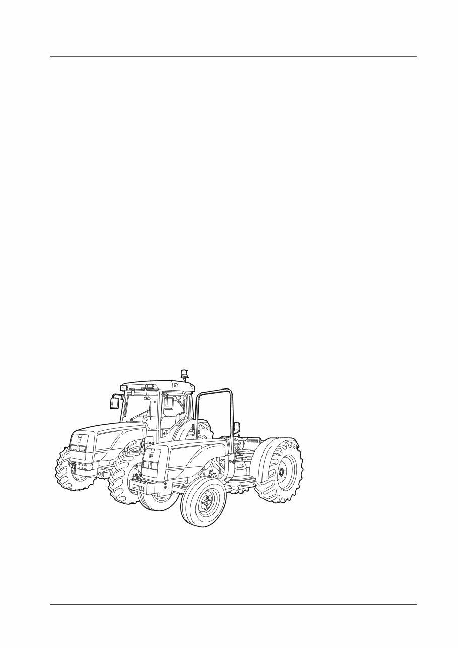
3300 Series Tractor Workshop Manual
3300 Series - Issue 1
Publication No 1857 251 M1
Volume 1
CONTENTS
Section No Description
1 INTRODUCTION, SAFETY NOTES ETC.
2 SPLITTING THE TRACTOR
3 ENGINE SPECIFICATIONS
4 CLUTCH
5 GEARBOXES
6 REAR AXLE
7 POWER TAKE-OFF
8 FRONT AXLE
9 HYDRAULICS
10 ELECTRICAL SYSTEM
11 ELECTRONICS
12 CAB AND SHEET METAL
Published by:
AGCO Limited,
Banner Lane September 2001
Coventry, Issue 1
England CV4 9GF © AGCO Limited 2001

3300 Series -Issue 1 1A–1
Introduction and Safety in the Workshop
Section 1 - A
Table of Contents
Description Page No.
Introduction ..............................................................................................1A- 2
Safety in the Workshop ............................................................................1A- 4

Introduction and Safety in the Workshop
1A–2 3300 Series - Issue 1
INTRODUCTION
The purpose of this manual is to assist Dealers and
Distributors in the efficient repair and maintenance of
Massey Ferguson farm machinery. Carrying out the
procedures as detailed, together with the use of special
tools where appropriate, will enable the operations to be
completed within the time stated in the Repair Time
Schedule.
To assist with locating information, each section of the
manual is preceded by a contents page listing the
operations. Each instruction within an operation has a
sequence number, and to complete the operation in the
minimum time it is essential that these instructions are
performed in numerical sequence commencing at 1,
unless otherwise stated.
When applicable, these sequence numbers identify the
components in the appropriate illustration. Where an
operation requires the use of a special tool, the tool
number is quoted under the operation heading and is
repeated in, or following, the instruction involving its use.
Indexing
For convenience the manual is divided into sections and
parts, each page bearing a section and part number. The
sections are subdivided into numbered operations.
Example: 1-7A would be Operation 1 in Section 7, Part A.
This simplifies cross referencing and enables the subject
to be found easily.
Definition of Terms
The operation descriptions generally used throughout the
schedules may be defined as follows:
Removal and Refitment - Remove and refit an original
part or assembly, or a new part or assembly which does
not involve additional operations or time.
Install - Install a part or component not previously fitted
e.g., accessories.
Overhaul - Remove a part or assembly, dismantle,
inspect and recondition, re-assemble, and re-install
making all necessary adjustments.
Dis-assembly and Re-assembly - The terms `Dis-
assembly' and `Re-assembly' indicate the orderly taking
apart of an assembly into individual parts and rebuilding it
into the original assembly.
Adjust - Make the necessary adjustments to restore
specified setting or performance.
Check - Ascertain if a setting or condition is within the
limits of acceptability, either as defined in the
manufacturer's specifications or, where a dimension is
not specified, in the judgement of the mechanic. The
checking of fixings, e.g. nuts and bolts, includes
tightening to the specified torque figures listed in this
Manual.
Servicing - All technical work undertaken to maintain the
machine in working order.
Special Tools
Where the use of a special tool is specified in an operation
the tool number will be shown under the operation
heading and also following the instruction requiring its
use.
The use of the special tools mentioned in the text
contributes to a safe, efficient and profitable repair. Some
operations are impracticable without their use, for
example, the refitment of the differential unit.
Distributors and Dealers are therefore urged to check
their tools against the list provided. Where necessary,
tools may be ordered from: AGCO Limited. Product
Reliability, Banner Lane, Coventry. CV4 9FG (Phone 44
024 76 694400) (Fax 44 024 76 852318).
For further details, refer to the special tool catalogue for
this range of tractors, Publication No. 1856 550 M5, or
Section 14 of this manual.
Repairs and Replacements
When service parts are required it is essential that only
genuine Massey Ferguson replacements are used.
Attention is particularly drawn to the following points
concerning repairs and the fitting of replacement parts
and accessories:
Safety features embodied in the tractor may be impaired
if other than genuine parts are fitted.
In certain territories, legislation prohibits the fitting of
parts not to the tractor manufacturer's specification.
Torque wrench setting figures given in the Workshop
Manual must be strictly adhered to. Locking devices
where specified must be fitted. If the efficiency of a
locking device is impaired during removal it must be
renewed.
The tractor warranty may be invalidated by the fitting of
other than genuine Massey Ferguson parts. All Massey
Ferguson replacements have the full backing of the
manufacturer's warranty. Massey Ferguson Distributors
and Dealers are obliged to supply only genuine service
parts.
Repair of the Tractor
Follow these important points:
CLEAN THE TRACTOR AND DIAGNOSE THE FAULT
BEFORE DIS-ASSEMBLY.
If possible, make a complete diagnosis to determine the
extent of the repair required. Take precautions, as
necessary, to prevent dirt or other foreign material
entering the hydraulic, fuel or air systems.
DO NOT MIX PARTS.
Make particular note of special parts which should not be
interchanged.
DURING DIS-ASSEMBLY, CLEAN PARTS THOROUGHLY
AND INSPECT THEM FOR WEAR, DAMAGE, ETC.
LABEL PARTS. PROTECT PRECISION OR MACHINED
SURFACES.

Introduction and Safety in the Workshop
3300 Series -Issue 1 1A–3
Amendments
Under normal conditions revised pages are issued
carrying the same number as the existing pages requiring
amendment. The new pages are inserted in place of the
existing ones. The old pages should then be destroyed.
The issue number is printed on the bottom of each page,
e.g. Issue 1, 2 or 3 etc.
In some cases additional pages or completely new
sections may be issued. These pages are to be inserted
immediately following the page carrying the next lowest
page number, or section number as appropriate.
Where new pages are required to be positioned between
existing pages, the new page numbers will contain a
suffix letter - example: New page number 7A-16a.
This page is inserted after existing page number 7A-16
and before page number 7A-17. Correspondingly a further
new page numbered 7A-16b would be positioned after
7A-16a but before 7A-17.
To ensure that a record of amendments to this manual is
readily available, the list of amendments will be re-issued
with each set of revised pages, quoting the amendment
number, date of issue and appropriate instructions.
NOTE: Service Bulletins and Amendment Sheets are
issued to the Massey Ferguson Distributors and Dealers
only and are not for general circulation.

Introduction and Safety in the Workshop
1A–4 3300 Series - Issue 1
SAFETY ALERT SYMBOL AND TERMS
This safety alert symbol means
ATTENTION! BECOME ALERT! YOUR
SAFETY IS INVOLVED!
The safety alert symbol identifies important safety
messages on machines, safety signs, in manuals, or
elsewhere. When you see this symbol, be alert to
the possibility of personal injury or death. Follow the
instructions in the safety message.
Why is SAFETY important to you?
★ ACCIDENTS DISABLE and KILL ★
★ ACCIDENTS are COSTLY ★
★ ACCIDENTS can be AVOIDED ★
SAFETY in the WORKSHOP
This safety section of your Workshop Service manual is
intended to point out some of the basic safety situations
which may be encountered during the normal repair
operations of the tractor, and to suggest possible ways of
dealing with these situations.
Additional precautions may be necessary, depending on
the type of repair and the conditions at the work site or in
the workshop. Massey Ferguson has no direct control
over the repair procedures, operation, inspection,
lubrication or general maintenance. Therefore it is YOUR
responsibility to use good safety practices in these areas.
SAFETY - A WORD to the MECHANIC
It is your responsibility to read and understand this safety
section before carrying out repairs on Massey Ferguson
equipment.
Remember that YOU are the key to safety. Good safety
practices not only protect you, but also the people around
you. Study the features in this section and the rest of the
manual and make them a working part of your safety
programme. Practice all other usual and customary safe
working precautions, and above all – REMEMBER –
SAFETY IS YOUR RESPONSIBILITY. YOU CAN
PREVENT SERIOUS INJURY OR DEATH.
SAFETY - DANGER, WARNING and
CAUTION
Whenever you see these signal words and symbol
used in this manual and on decals, you MUST take note
of their instructions.
DANGER: The symbol and the word DANGER
indicates an imminently hazardous situation which,
if not avoided, will result in DEATH OR VERY
SERIOUS INJURY.
WARNING: The symbol and the word WARNING
indicates a potentially hazardous situation. If the
instructions or procedures are not correctly followed
it could result in PERSONAL INJURY, OR LOSS OF
LIFE.
CAUTION: The symbol and the word CAUTION is used
to indicate a potentially hazardous situation that, if not
avoided, may result in MINOR OR MODERATE INJURY.
IMPORTANT: The word IMPORTANT is used to identify
special instructions which, if not observed, could result in
damage to, or destruction of the machine, process or its
surroundings.
NOTE: The word NOTE is used to indicate points of
particular interest for more efficient and convenient
repair or operation.

Introduction and Safety in the Workshop
3300 Series -Issue 1 1A–5
SAFETY DECALS
WARNING: DO NOT remove or obscure Danger,
Warning or Instruction Decals.
Replace any Danger, Warning, Caution or Instruction
Decals that are not readable, damaged or are missing.
GENERAL
Practically all service work involves the need to drive a
tractor. The Operator Instruction Book, supplied with
each tractor or implement, contains detailed safety
precautions relating to driving, operating and servicing.
These precautions are as applicable to the service
mechanic as they are to the operator, and should be read,
understood and practised by all personnel.
Prior to undertaking any maintenance, repair, overhaul,
dismantling or re-assembly operations, whether within a
workshop facility or out 'in the field', consideration should
be given to factors that may have an effect upon Safety,
not only upon the mechanic carrying out the work, but
also upon bystanders.
• DO NOT allow children or bystanders around or on
the machine while it is being adjusted, serviced,
repaired or operated.
PERSONAL CONSIDERATIONS
Clothing
• The wrong clothes or carelessness in dress can
cause accidents. Check to see that you are suitably
clothed. DO NOT wear loose clothing or long hair
around equipment.
Some jobs require special protective equipment
Eye Protection
• The smallest eye injury may cause loss of vision.
Injury can be avoided by wearing the proper eye
protection when engaged in chiselling, grinding,
discing, sanding, welding, painting etc.
• Wear safety goggles or safety glasses appropriate to
the job in hand.
Breathing Protection
• Fumes, dust and paint spray are unpleasant and
harmful. These can be avoided by wearing
respiratory protection.
Hearing Protection
• Loud noise may damage your hearing and the greater
the exposure the worse the damage. If you think the
noise is excessive, wear ear protection.
Hand Protection
• It is advisable to use a protective barrier cream
before work to prevent irritation and skin
contamination. After work clean your hands in soap
and water. Solvents such as white spirit, paraffin,
etc., may harm the skin.
• Wear gloves when ever possible to protect your
hands. DO NOT wear rings or wrist watches when
working on machinery, as they could catch on
moving parts and cause serious injury.
Foot Protection
• Substantial or protective footwear with reinforced
toe-caps (safety shoes) will protect your feet from
falling objects. Additionally, oil-resistant soles will
help to avoid slipping.
Special Clothing
• For certain work it may be necessary to wear flame
or acid-resistant clothing.
EQUIPMENT CONSIDERATIONS
Machine Guards
• Before using any machine, check to ensure that the
machine guards are in position and serviceable.
These guards not only prevent parts of the body or
clothing coming in contact with the moving parts of
the machine, but also ward off objects that might fly
off the machine and cause injury. Ensure that
missing guards are replaced.
Lifting Appliances
• Always ensure that lifting equipment, such as
chains, slings, lifting brackets, hooks and eyes are
thoroughly checked before use. If in doubt, select
stronger equipment than is necessary.
• Never stand under a suspended load or raised
implement.
• Avoid injury through incorrect handling of
components. Make sure you are capable of lifting the
object. If in doubt get help.
Jacking
• Select a jack strong enough to carry the load.
• Stabilise the tractor and chock the wheels.
• Put support stands under the tractor. Lower the jack
and let the tractor rest on the stands.
• DO NOT go under a tractor supported by a chain
hoist or jack.

Introduction and Safety in the Workshop
1A–6 3300 Series - Issue 1
Compressed Air
• The pressure from a compressed air line is often as
high as 7 bar (100 lbf/in²). It is perfectly safe if used
correctly. Any misuse may cause injury.
• Never use compressed air to blow dust, filings, dirt
etc., away from your work area unless the correct
type of nozzle is fitted and eye protection is used.
• Compressed air is not a cleaning agent, it will only
move dust, etc., from one place to another. Look
around before using an air hose as bystanders may
get grit into their eyes, ears or skin.
• Used approved air guns, wear safety goggles, and
use proper shielding to protect others in the work
area.
• Never point an air nozzle at a persons body.
Hand Tools
• Many cuts, abrasions and injuries are caused by
defective tools. Never use the wrong tool for the job,
as this generally leads either to some injury, or to a
poor job.
• Never use:–
- A hammer with a loose head or split handle.
- Spanners or wrenches with splayed or worn jaws.
- Spanners or files as hammers; or drills, clevis pins
or bolts as punches.
• Grind off mushroom heads from chisels. The sharp
edges can tear your skin if the tool slips. And, when
the tool is struck, chips could break off and fly into
your eyes.
• Keep a handle on every file to prevent the tang from
piercing your palm or wrist if the file should slip or
catch.
• For removing or replacing hardened pins use a
copper or brass drift rather than a hammer.
• For dismantling, overhauling and assembly of major
components, always use Special Service Tools
recommended. These will reduce the work effort,
labour time and repair cost.
• Always keep tools clean and in good working order.
Electricity
• Electricity has become so familiar in day to day
usage, that its potentially dangerous properties are
often overlooked. Misuse of electrical equipment
can endanger life.
• Before using any electrical equipment - particularly
portable appliances - make a visual check to make
sure that the cable is not worn or frayed and that the
plugs, sockets, etc., are intact; make sure you know
where the nearest isolating switch is located. Always
use an earthed (grounded) 3 pin electrical cord.
GENERAL CONSIDERATIONS
Solvents
• Use only cleaning fluids and solvents that are known
to be safe. Certain types of fluids can cause damage
to components such as seals, etc., and can cause
skin irritation. Solvent labels should be checked that
they are suitable not only for the cleaning of
components and individual parts, but also that they
DO NOT affect the personal safety of the user.
Housekeeping
• Many injuries result from tripping or slipping over or
on, objects or material left lying around by a careless
worker. Prevent these accidents from occurring. If
you notice a hazard, don't ignore it - remove it.
• A clean, hazard-free place of work improves the
surroundings and daily environment for everybody.
• Keep work organised and clean. Wipe up spills of any
kind to minimise the possibility of a fall. Keep tools
and parts off the floor to further reduce the possibility
of tripping and causing serious injury.
Fire
• Fire has no respect for persons or property. The
destruction that fire can cause is not always fully
realised. Everyone must be constantly on guard.
- Extinguish matches, cigars, cigarettes, etc., before
throwing them away.
- Work cleanly, disposing of waste material into
proper containers.
- Locate the fire extinguishers and find out how to
operate them.
- DO NOT allow or use open flame near the fuel tank,
fuel lines, battery, hydraulic hoses or component
parts
• When using a gas torch, always keep a fully charged
fire extinguisher within reach.
• In the event of fire:
- DO NOT panic - warn those near and raise the
alarm.
First Aid
• In the type of work that mechanics are engaged in,
dirt, grease, fine dust, etc. all settle upon the skin and
clothing. If a cut, abrasion or burn is disregarded it
may be found that an infection has formed within a
short time. What appears at first to be trivial could
become painful and injurious. It only takes a few
minutes to have a fresh cut dressed, but it will take
longer if you neglect it. Make sure you know where
the First Aid box is located and that it is kept fully
stocked at all times.

Introduction and Safety in the Workshop
3300 Series -Issue 1 1A–7
Operational considerations
• Stop the engine, if at all possible, before performing
any service.
• Place a warning sign on self propelled equipment
which, due for service or overhaul, would be
dangerous to start. Disconnect the battery leads if
leaving such a unit unattended and remove the key.
• DO NOT attempt to start the engine while standing
beside the tractor or attempt to by-pass the safety
start switch. Make a practise of checking that neutral
start switches are functioning correctly.
• Avoid prolonged running of the engine in a closed
building or in an area with inadequate ventilation as
exhaust fumes are highly toxic.
• Always turn the radiator cap to the first stop to allow
pressure in the system to dissipate when the coolant
is hot.
• Never work beneath a tractor which is on soft
ground. Always take the unit to an area which has a
hard level working surface - concrete is preferred.
• If it is found necessary to raise the equipment for
ease of servicing or repair, make sure that safe and
stable supports are installed, beneath axle housings,
casings, etc., before commencing work.
• Certain repair or overhaul procedures may
necessitate ‘Separating the tractor’, either at the
engine gearbox or gearbox/rear axle locations. These
operations are simplified by the use of the Tractor
Splitting Kit/Stands (Use the Massey Ferguson
MF.3012 Tractor Splitting Track, also available,
MF.3013 Cab Stands). Should this equipment not be
available, then every consideration must be given to
stability, balance and weight of the components,
especially if a cab is installed.
• Use footsteps or working platforms when servicing
those areas that are not within easy reach.
• Cleanliness of the tractor hydraulic system is
essential for optimum performance. When carrying
out service and repairs plug all hose ends and
component connections to prevent dirt entry.
• Clean the exterior of all components before carrying
out any form of repair. Dirt and abrasive dust can
reduce the efficiency and working life of a
component and lead to costly replacement. Use of
high pressure washer or steam cleaner is
recommended.
• Before loosening any hoses or tubes connecting
implements to remote control valves, etc., switch off
the engine, remove all pressure in the lines by
operating levers several times. This will remove the
danger of personal injury by oil pressure.
• Prior to pressure testing, make sure all hoses and
connectors not only of the equipment, but also those
of the test equipment, are in good condition and
tightly sealed. Pressure readings must be taken with
the gauges specified. The correct procedure should
be rigidly observed to prevent damage to the system
or equipment, and to eliminate the possibility of
personal injury.
• Hydraulic fluid escaping under pressure can have
enough force to penetrate the human skin. To locate
a leak under pressure, use a small piece of
cardboard, never use your hands. If you are injected
with hydraulic fluid seek medical help immediately.
• When equipment or implements are required to be
attached to the hydraulic linkage, either for testing
purposes or for transportation, the ‘Position Control’
should be used.
• Always lower equipment to the ground when leaving
the tractor.
• If high lift attachments are installed on a tractor
beware of overhead power, electric or telephone
cables when travelling. Drop the attachment near to
ground level to increase stability and minimise risks.
• DO NOT park or attempt to service the equipment on
an incline. If unavoidable, take extra care and chock
all wheels.
• Observe recommended precautions as indicated in
this Service Manual when dismantling the air
conditioning system as escaping refrigerant can
cause frostbite.
• Prior to removing wheels and tyres from a tractor,
check to determine whether additional ballast (liquid
or weights) has been added. Seek assistance and
use suitable equipment to support the weight of the
wheel assembly. Store the wheel so that they cannot
fall over and cause injury.
• When inflating tyres beware of over inflation -
constantly check the pressure. Over inflation can
cause tyres to burst and result in personal injury.
Heed these safety precautions, and the ones found in this
manual, and you will protect yourself accordingly.
Disregard them and you may become injured for life.
Servicing techniques
Service Safety
Appropriate service methods and proper repair
procedures are essential for the safe, reliable operation of
all farm machinery as well as the personal safety of the
individual doing the work.

Introduction and Safety in the Workshop
1A–8 3300 Series - Issue 1
This Service Manual provides general directions for
accomplishing service and repair work with tested,
effective techniques. Following them will help assure that
a thorough repair is successfully completed.
There are numerous variations in procedures, techniques,
tools, and parts for servicing tractors, as well as in the skill
of the individual doing the work. This Manual cannot
possibly anticipate all such variations and provide advice
or cautions as to each. Anyone who departs from the
instructions provided in this Manual must realise that one
compromises their personal safety and the tractor's
integrity by the choice of repair methods, tools and/or
parts.
Service Techniques
Clean the exterior of all components before carrying any
form of repair. Dirt and abrasive dust can reduce the
efficient working life of a component and lead to costly
replacement.
Time spent on the preparation and cleanliness of working
surfaces will pay dividends in making the job easier and
safer and will result in overhauled components being
more reliable and efficient in operation.
Use cleaning fluids which are known to be safe. Certain
types of fluid can cause damage to ‘O’ rings and cause
skin irritation. Check the label on Solvents to ensure that
they are suitable for the cleaning of components and also
that they DO NOT risk the personal safety of the user.
Replace ‘O’ rings, seals or gaskets whenever they are
disturbed. Never mix new and old seals or ‘O’ rings,
regardless of condition. Always lubricate new seals and
‘O’ rings with hydraulic oil before installation.
When replacing component parts use the correct tool for
the job.
Hoses and Tubes
Always replace hoses and tubes if their ends are
damaged.
When installing a new hose, loosely connect each end
and make sure the hose takes up the designed position
before tightening the connection. Clamps should be
tightened sufficiently to hold the hose without crushing
and to prevent chafing or contact with other parts.
Before removing hoses or tubes make sure they are
identified so that they can be correctly re-assembled.
Be sure any hose which has been installed is not kinked
or twisted after it is tightened.
Bearings
Bearings which are considered suitable for further service
should be cleaned in a suitable solvent and immersed in
clean lubricating oil until required.
DO NOT spin bearings with compressed air. The
centrifugal force could cause a ball or roller to fly outward
with enough force to cause an injury.
Installation of a bearing can be classified in two ways:
press fit on rotating parts such as shafts, and gears, and
push fit into static locations such as reduction gear
housings. Where possible, always install the bearing onto
the rotating component first.
Always use pullers or a press to remove and/or install
bearings, bushings and cylinder sleeves, etc. Use
hammers, punches and chisels only when absolutely
necessary and be sure to wear safety goggles.
Shims
When shims are removed, tie them together and identify
them as to location. Keep shims clean and flat until they
are re-installed.
Gaskets
Be sure the holes in the gasket correspond with the
lubricant passages in the mating parts. If gaskets are to
be made, select material of the proper type and
thickness. Be sure to cut holes in the right places. Blank
gaskets can cause serious damage - always renew
gaskets prior to re-installation.
Lip Type Seals
Lubricate the lips of the lip-type seals before installation.
Use petroleum jelly. DO NOT use grease. Ensure that the
oil seal is fitted the right way round, the lip of the seal is
placed next to the lubricant that is sealed. Some seals
have a second auxiliary lip, which is used to prevent the
ingress of dirt to the seal lip.
If, during installation, the seal lip must pass over a shaft
that has splines, a keyway, rough surface or a sharp edge,
the lip can be easily damaged. Always use a seal
protector, when one is provided.
Use of Bolts in Blind Holes
Use bolts of the correct length. A bolt which is too long
may ‘bottom’ before the head is tight against the part it is
to hold. The threads can be damaged when a `long' bolt
is removed. If a bolt is too short, there may not be enough
threads engaged to hold the part securely.
Locking Devices
Lockwashers, flat metal locks or split pins are used to lock
nuts and bolts.
Flat metal locks must be installed properly to be effective.
Bend one end of the lock around the edge of the part.
Bend the other end against one flat surface of the nut or
bolt head. Always install new locks.
Always fit new split pins/cotter pins and bend the ends
round so that they will not catch in clothing and help to
prevent cuts.
Cables and Wires
When removing or disconnecting a group of cables or
wires, tag each one to assure proper re-assembly.
Always clip back wires and cable looms properly to
prevent chafing, cable damage and possible damage by
fire.

Introduction and Safety in the Workshop
3300 Series -Issue 1 1A–9
Tractor specifications:
Engine
Fuel System
Air System
Cooling System
Make: Perkins diesel to Massey Ferguson specification.
Type: Four stroke, water cooled, direct injection.
Models applicable:
3315 903.27, 55 ISO at 2250 rev/min.
3325 903.27T, 65 ISO at 2250 rev/min.
3330 1004.40, 68 ISO at 2200 rev/min.
3340 1004.42,80 ISO at 2200 rev/min.
3350 1004.40T,91 ISO at 2200 rev/min.
3355 1004.40T, 95 ISO at 2200 rev/min.
Cylinders 3 or 4
Engine power and torque
Consult the sales promotional leaflet for your model of
tractor issued by your local Massey Ferguson Dealer at
time of sale.
Idle speed - all models 750 + 25 rev/min.
Rated speed - all models see above.
Maximum no load speed:
3315, 3325 2410 + 25 rev/min.
3330, 3340 2350 + 25 rev/min.
3350, 3355 2310 + 25 rev/min.
Valve tip clearance:
All tractors - Inlet (hot or cold) 0,20 mm (0.008 in).
All tractors - Exhaust (hot or cold) 0,45 mm (0.018 in).
Fuel lift pump Mechanical, driven from camshaft, hand primed.
Fuel Filter CAV canister type filter.
Water sedimentor CAV with transparent sediment bowl.
Injection Pump CAV distributor type with mechanical governor.
Injectors CAV nozzles and holders.
Starting aid CAV thermostatic.
Type
Two stage dry element with warning light. Removable
main and secondary element.
Type
Thermostat controlled with centrifugal pump to assist
circulation multi-blade fan driven by a single or double
belt from the crankshaft pulley.
Radiator pressure cap rating 0,75 bar (10 lbf/in
2
).
You're Reading a Preview
What's Included?
Fast Download Speeds
Online & Offline Access
Access PDF Contents & Bookmarks
Full Search Facility
Print one or all pages of your manual
$46.99
Viewed 19 Times Today


Secure transaction
What's Included?
Fast Download Speeds
Online & Offline Access
Access PDF Contents & Bookmarks
Full Search Facility
Print one or all pages of your manual
$46.99
- The Massey Ferguson MF 3300 Series MF-3315, MF-3325, MF-3330, MF-3340, MF-3350, MF-3355 Tractor Service Workshop Repair Manual provides detailed servicing instructions for professional mechanics and DIY enthusiasts.
- This comprehensive manual offers complete step-by-step information on repair, servicing, preventative maintenance, and troubleshooting procedures for the Massey Ferguson Tractor.
- It features photos, illustrations, and detailed instructions to guide you through the entire repair process, making it an indispensable source of maintenance and repair information.
- The manual covers all necessary information to keep your Massey Ferguson MF 3300 Series Tractor working correctly, helping to lower repair and maintenance costs.
- Serial numbers covered include MF 3315, MF 3325, MF 3330, MF 3340, MF 3350, and MF 3355.
- It is instantly accessible and available in a printable format, with fully bookmarked chapters for easy navigation.
- Subjects covered in this manual include engine data, clutch, gearboxes, rear axle, hydraulics, electrical system, fuel and air system, cooling system, brakes, steering, and more.
- Additional subjects covered are tractor identification, weights and dimensions, engine specifications, transmission specifications, power take-off specs, hydraulic circuit specifications, and more.
- Technical specifications of the transmission unit, hydraulic pump, filters, power steering, wiring diagrams, sensor locations, seals, bearings, and O-ring seals are also included.
If you are looking to purchase this Massey Ferguson MF 3300 Series MF-3315, MF-3325, MF-3330, MF-3340, MF-3350, MF-3355 Tractor Shop Manual service repair manual, select the instant format. After purchasing, you can instantly access and view the manual, and it is fully printable for your convenience.


