Farmall IH Super A Tractor Special Attachments Owners User Installation Manual -
What's Included?
Lifetime Access
Fast Download Speeds
Online & Offline Access
Access PDF Contents & Bookmarks
Full Search Facility
Print one or all pages of your manual
SPECIAL ATTACHMENTS FO R I NTERNATJONAL SUPER -A TRACTORS Internati onaL Super -A trac tors are designed and ~qui ppcd to meet the r equ ir e ment s of th e g r eat.e50 t number n! use r s, bu t s pecial jobs or pa. r ti cu lar c ondi ti ons freque ntly requiTe ad diti ona l eq ui pment. The a tt a chment s shown in thi s m anua l includ e pow er takc -offs and othe r means to exte nd th e applica tion a. nd increase th e co nveni ence and eflic i ency of the tra cto r' s powe r. Pres e rve thi s manual with your ope r atoX"s manua l, as your guide in in stall atio n, ca r e a nd o pe r- ation of you r spedi'll attac h ments. For any se r vice or repa iT refer to yo ur ln ternational Ind us t:dal Powe r dist ri butor or dea ler. CONTENTS El ectTic sta rtin g a n d lighti n g . 2-5 Belt pulle y and power ta ke-off 6 -8 H yd raul ic po wer lift 9 Radi ato r sh utte r 10- 1 J Exha ust muHler 12 Spa r k a r r ester . . . . . • . • • • • • • . 12 Pre - cleaner . • Pre - sc rC'lenl':r Ai r pipe exte nsion Wh e el weight s . . . . . . . . . . . . . . . 14 Adju stable (ront wh ee l IS Swi ngi ng d. ra w bar ... • 16 Pintl e h ook . . . . . . . . • . ••.. , . . )6 It is the po li cy of l ntc rn atio na l H a rve~ter Compa ny to imp rov e i t s pr od uc ts whenever it is po ssi ble ;lnd p ra ctica l to do so. We reserve the right to make cha nge s and n dd i mp ro ve - m ents at any time wit h out in c ul:ring any oblig a tion to m3 ke suc h c han ges on tractors or at t ac hments so ld pr evious l y,
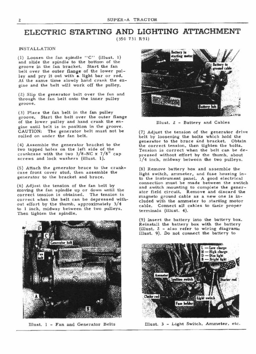
, SUPER-A TRACTOR ELECTRIC STARTING AND LIGHTING ATTACHMENT (350731 R<JI) INSTALLAT ION ( 1) Loo .. " .. the fan apindle "C" (ill .. at. I) and , Ud" the apindl. to the bo tt om of the gr oove in the (lUI. b ra cket. St.r\ the f an be lt o ve r the o uter fiaull" of th e lo .... er pul- lay a.nd pr y it ou t with .. light bar or rod. At t he SIlln. tima .low ly h and cra nk the en- g ine ..,d the be lt wUI work o C! the pulley. (ll Slip th e gen er ator belt ov er th .. h .n a.nd throuxh the ran be lt o nto the inner pulley groove. P) Place the bn b ell in the Ian pulley groove. Start the belt ov er the ou tu !lange of the lo wer pulle y and hand c rlUlk the en- gine until be lt ill in !'oaltion in the groove. CAUTI ON: The g ene ra to r b,, 1t mud D ot be rolled on under the r an bel t. (4) An ",",bl" the g. m., r atQ r br.:l.cket to t he two tapped hole,. on the le ft ai d. of the c nnkc •• e wlt.h the twO J/ 8_N C x 7/8" ca p acreW/l an d loc k "" •• hers (Illu st. 1). (5 ) Attach the Iile n ", r ato r bu .c::", to th. cra nk - Caae front cover .tud, then .... "'mble th .. lIene r ato r to the bra ck et and bn.ce. (to) Adjust the tendon o f thor !An be lt by moving I h. lan spindle up or down u nU I t be co rr ect t ensio n i. ob taine d. The t ension ig c orrec t whln the belt ca n b l') depres.ed witb- out efior t by thl') thumb , appro lLiroau, ly l/4 to I inch, mi dway between th e two pulle ys. Then Ugh, en the spindle . Ulu a t. I _ F a n and Genl')ra.tor Belt , lll uliOt. l _ aattery snd Cable. (7) Ad ju &t the te nglo n of the generator dr ive belt by loose ninil the bolt. whi ch ho ld the generator to t he brace "nd brac.ket. O bLa i n the correct tens i nn , then UgMe n th e bo lt •• T en~ion is correc.t when the belt ca n b", de- preased wi thou t effo rt by the thumb. about 1/ 4 Inch, midway between th e two pul l .. ys. (8) Remov .. battery box . nd a, se m bi. the Hllht .wi tch , arruneter, .nd fu.e ho u. ing in- to the inll tru me nt p&nd. A good electr lc. l cOWlection mu.t be msde bet"" ...... th e . wit ch and .. wit ch lTIOunUng to com pl et. the &en.. r- ato r fiel d circlait. Rem ov e ~d di.c ard the magneto grO land ca ble a. a new on e ia in- clud .. d with the anvneter to sta rt ing mo tor c .. bl... COlUlec t.1I ca blel to tiI. .. ir pro pe1' te1'minah (Hlu.t. 4 ). (9 ) ln s ~rt the b ltte Ty into t he batury box. R~inlllall the b ltl.e1'Y box ""l th the batte ry (Wust. l _ aJ 10 uhr to wiTing diag ra m, il hu t. 9 ). Do no t conn .. ct the bl tlc'r y to
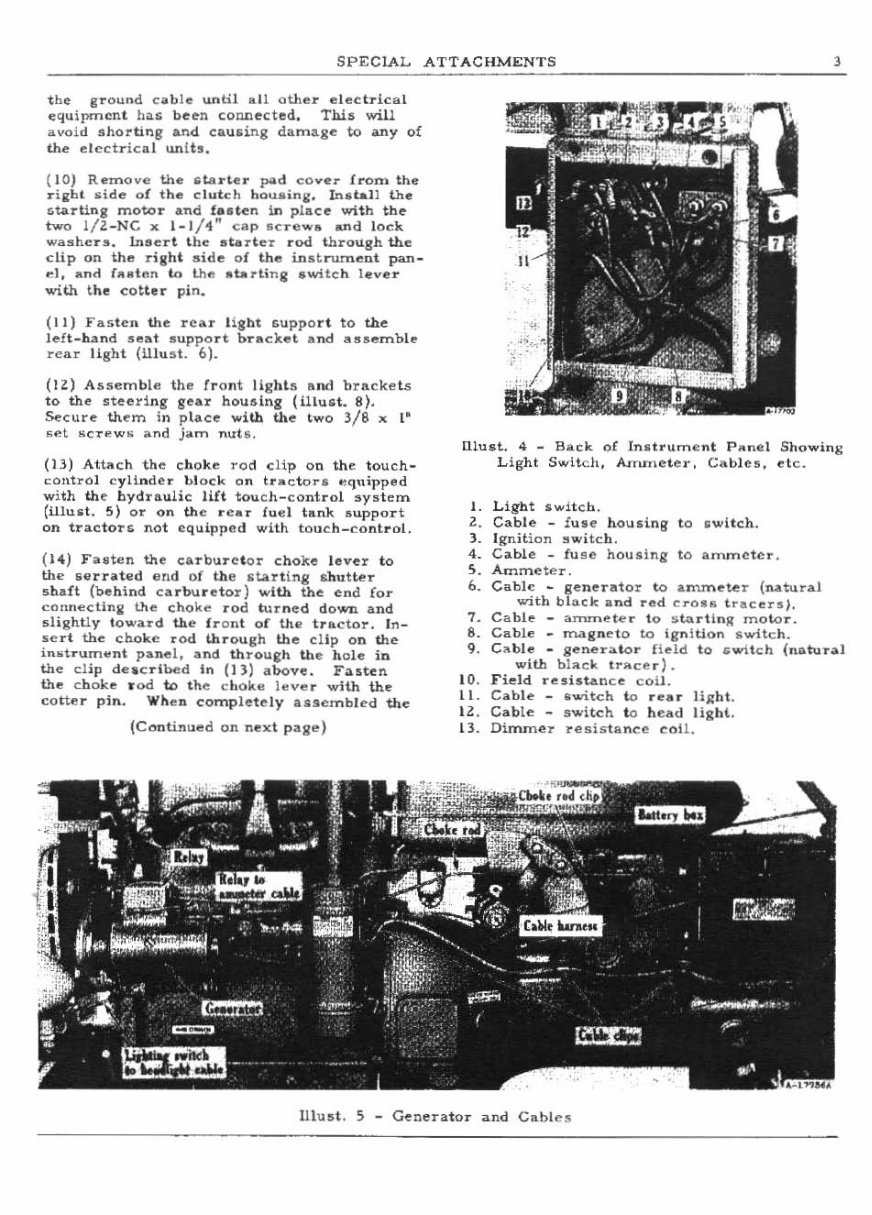
SPECIAL ATTACHMENTS 3 the ground cable until .. II oU,e " elec tr ic .. 1 equi}>tT1cnt haG been connected . This will "voi d .!Iho .. ting a.n d. caulOing damage to any of the elcdrical unLh . ( 10) Remove the starl.e .. pold cO .. .,r Iron. the .. iRbl llid .. 01 the clutch hou .. ;n~. In,,t,,-Il the ctOlrting motor and fasten In place with tbe two I/Z_NC x 1_1 / 1" cap sc rew,", and lock wash" .. ". In"'"rt th e .. e-rter r od through th., clip on the rig ht s i d.., 01 the in st rument pan_ d . .. nd ( .. ~t"n in the .. t..rUnlj switc h l ev.,r with t he cOUa .. pin. (II) F a" ten the rear !iaM Guppor t to the left-hand seat support hT",ck". lind """emble rear light (11lu!lt. 6). (Ill A5lIemble the fr ont lIghb and brAckets to the steer:lng gea .. housing (Hlu .. t. 8). Secure them in pl ace with the two 3/8 x '" ~"t IICTI! W II ;>.nd jam nut s. (H) Atbch th e cho ke ro d clip on the to uch - control cylinde r bl oc k on tra ctor. "quipped with the hydraulic lilt tou ch - control !Iy!lt em (i1lust. 5) or on the rear fud tank aupport on tractors not equipped with touch_cont rol. ( 11) Fo uten th., carbure t or ehoke lever to the 6"rntill d ar!d of the sUr ting nutter s haft (behind ca rburetor ) with the end for c,,,,,,eeting the choke r od turned do wn and dightiy to .... ard the Ir o nt of the tractor. In- "c rt tb" choke rod through thfi! clip on the in .. trum .. nt panel. and throulj;l'l th e h ole in th e cli p de. c rl bed In (J l) above. Fa"ten the ch oke r od to the ch ok .. I.. v"r with th., coUe r pin. ...hea comp le tely iillscmb l ed th e (Continued on next page) UIU$t. 4 - BaCK of Inltrument PlOnel Showilll!: Light Switch . N lUlleter, Cabl es . .,tc. 1. Light Switch. Z. Cab le - Iuse houling to switch. 1. I gn;tioll """itch. 4. Cable _ fU $e hou.lng to anvneter . S. Ammeter. 6. Cabi" _ generator to a n'lmlHer (na.tural with black a nd rad CrOla tracersl. 7. Cable - arnrneter to ,. t.\>.rUnll moto r. 8. Cable _ mag n eto to ;g,, \ tion switch. 9. C"ble - g .. ner"'1or ne ld to .. witeh (natura l with bi lle', tr .. ce r ). 10 . Field resistan ce coil. II. Cab le _ .witch to rear lig ht . I l. Cable - s witch to h es.d light . 11. Dinune:r rellistance coil . Ulust. 5 - Genera tor and Cable s
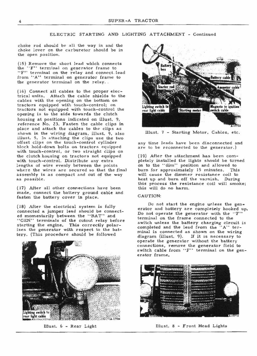
• SUPF.R _A TRACTOR ELECTR IC START lN G AND L.IGHT ING A TTAC HM ENT - Continued (hoke rod lihowd be all the way in and th~ choke lever on the c'lrooretor should be in the open position. (1 5) ReTnov .. the "ho rt ,,,, .«1. which conn",cta the " F" termin,,1 on gener"tor frame to "F" te rminll.i on the reh,y and connect . lead from "A" ter mi na l on genera to r £l' ame t ll. the gene r ator terminal o r.. th e relay. (16) Co nn ... ct a ll cab l es to the prope r dec- tr i cal unH a. Attac h the cable shield. to t he cables with the openi.ng on the bottom on tracwra equipped with tOil-en- cont rol; On tractorli. not equipped with tC>u<:h_cont rol the openio'lg Is to the a id e t oward. the clutcl\ housing at pos i tio ns indicated on il hut. 9, reference No. ZJ. Fasten the cab le cUps in place and atlach the cabl es to the cli p s a s .. hown in the wiring di.aeril.m . iHust. 9, abo LUust. S. In attaching the CH {l H us," t he two oU ..... t clip~ on the t ouch - control cylinder blnc'k hold-down boHIi on tractor ... equi pp ... d wi th t(>uch - control, (>r t wo btraight <:Lips on the clutch hou&lng on tr llctors not equipped with touch-control. Dilitrlbu te any extra lengths of wire evenly between lhe poinu wl'lf :re the wi res are secured $0 that the linal assemb ly is as compac t and out of tn " way a. posaible. ( 17) Alter all ot her connections have bee n made, connect t he batter y gTOWld coble and las t en the battery cover in pL" c p, (I S) Alter the e lect ric al s ystem is ful ly connected a jum per L .... d llooul d b ... conn ect_ ed momentarily be twee n the "SAT" and "GEN" term ;n",]" of the cutout relay beCore starting Ihe engine. Thill cor rectly po l ar- 17 .. e6 the gen ... r ato r with r .... pect IL> th ... ba t- tery. (Th is procedu re should be f ollowed Ul ust. b _ Rea r Light ll lus!. 7 - Star ti ng Mo to r. Cables. etc . any time lead s. have b<:en disco n nected and :ar" to be r ec onnected to th" generator.) ( 19) Aft"'r the a tt aelune nt ha s been com - plete ly in.s talled t he Lighh sho u ld be turned on to the "dim" position and allowed to buro lor lI pproximately 15 minutes. T hi s will cau"''' the dimme r r es i s"nce coi l to heat up and bur n oil the va1'ni~h. During th i, procns the r estatance co il will ,;moke; th is wi ll do no harm .. CAU TION: Dc not st art the "ngi ne un1e" the ien. er ator >md ba tt ery are com plet e ly hoolted up. Do n ot o~ril te t he generator with the " F" terminal on the frame conn e cted to the .s w itc h unlen the battery ch"' r gi 'l\ )! ci r cuit i5 com plet"d and the lead Cr am the " A" t er _ minal 1:> co n nected as shown on t he wirlng diag ram (illus t. 9). If it is n ecel106illry to operate the gene r ator without t he b",U eq' connec tions, remove the gener:ato r field to ", witch c", ble Cr am "F" t ermina l on the gen- er ator frame. Ui ust. 8 - F r<;>nt H ead l. i ghh
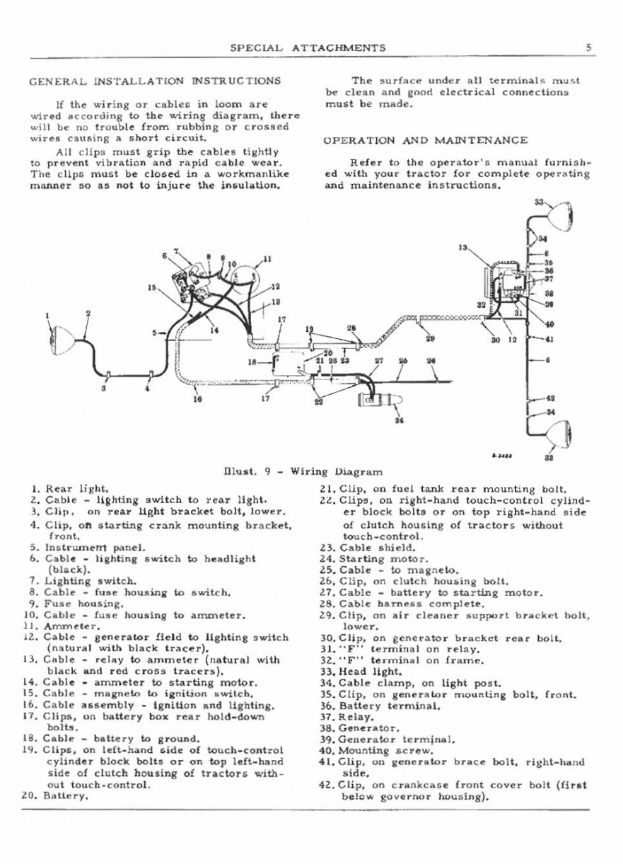
SPECLAL ATTACHMENTS , GENERAL lNSTALLATION INSTRUCTIONS Ii the wiring or cllble~ in loom are wired IIc cording to the wiring di"gnm, there will be no trou~le from rubbing or cro$8ed wi .. es cau,ing II ahort c i .. cuit.. All dlpn must grip the cables tilllhtly to p .. eve nt vib rat io n and .. apl d c",h ie wear. The c HI" mu1it be claISe<! in a workmanl ike manner '0 as not to in ju re the inlOul;oUo n. • , t • • " . .. -Ht -- • f," " .. " The aurf: .. ; .... "der all termin.l" m .. .. t be cl ean and eoon e le c trical connection" mu,t be m",de. OPERATION AND MADiTENANCE Rele .. to th", operator's manual f .. rn;,h- ed with your tractor for complete operating and maintenance In , tructions . "() M • " N N ~ " "- ~ " ~ • .. ...... t=;] .. Dlust. 9 Wiring Oiag .. am 1. Rear lig ht. Z. Gab le - Ufi:Mlng switch to re ar ligM. 3. Clip. on rea r llRht bracket bolt. lower. -I . Clip . on atart:il'lg cr;;)nk mounHng bra c ket . front. 5. InitrUlnerrt p.~nel. 6. Cable _ ligMi ng switch to h .... dlight ( black). 1. Ligbting ,wit ch. 8. C.ble - ruae hoUSWli to &....;Ich. 9. Fuae hou sing. 10. Cable - Cu.e MuainS to ",mmeter. II . Arnrnue r. lZ. Cable - geneutar Held to I1ght ina swl tt:h (n .. lura l with bl .. ck tucer) . 13. C .. ble - reIllY to ammeter (natural with black IU'Id red C.. 055 tracer ,,). 14. Cabl e _ ammeter to 5tsrting motor. 15. Cahle _ ,n"in",'" il.> ili: n iti <>n .. witch. 16. Cable auembly _ I gnition and Hghting. 17. C lip ~, on battery box rear hold - down bolts. 18. Cable _ battery to grOOUld . 19. Clip" on ldt-h .. nd &oide of touch_control cylinde .. block bolts Qr on 'k>p l elt-hand ,ide of clutch ho using of tn,c'k>I" with ~ ou t l ouch· control. lO. 8:,th, ry. Zl. CUp . on fuel tank rear mountirq;: bolt. Z~, Clip" on rieht - hand touch - control cylind- er block bolts or on top right - hand aide- of c lut ch ho .... ing of tr .. eto l's without tou c h_contl'ol . Z3. Cable alUeld. 24 . Sta rtin g moto r. 25. C .. ble - to maaneLo. 2b. Clip . on clu t ch hou~ing bolt. 21. Cable _ battery to st.1lrting m oto r. 28. C"b!e h ... ne .... complete. 29. Clip, on a ir cleaner ,;up~rl bracket bolt. lowe r. 30. Clip. on .:cne r .l.to .. bracket rear bo lt. 3 1. ·' F ·· le r mi na l on relay. 3Z. "F" t erm lnjOo! On f rame. 33. Head Ught. 34. C .. ble ciunp, on light post. 35. Clip. on ge" .... "to r mounting boH, fr o ,,!. 3b. Battery t erml1\;t.l. l7.Relay. 38 . Gene .. ato ... 19.Generat.or termina l. 40. Mountlng "crew. 41. Clip. on i,,,,,erlllor brace bo lt, ri!:hl-hto nd side. 4Z. C li p, on c ra nkc ase {ront cover bolt (Hr, t below governor ho using) .
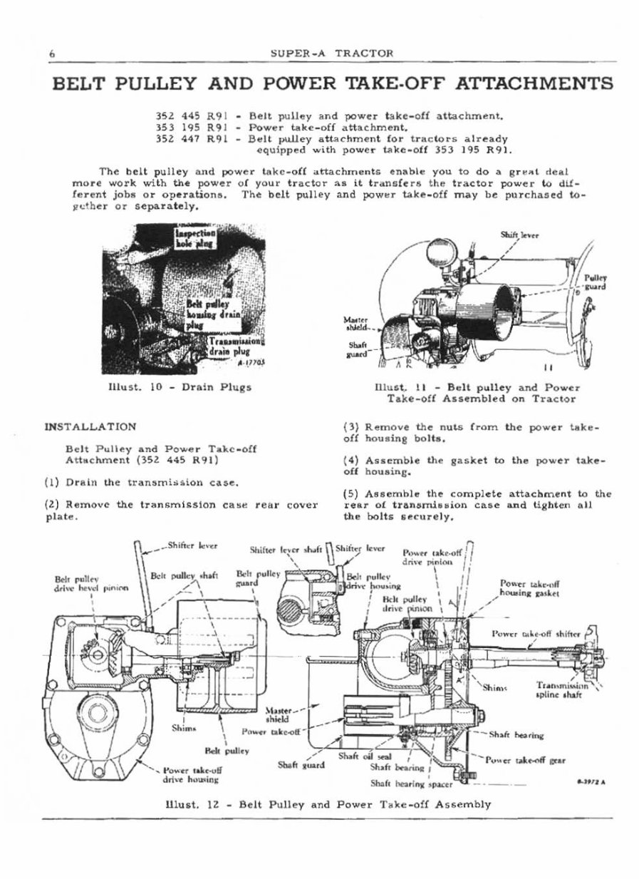
, SUPER_A TRACTOR BELT PULLEY AND POWER TAKE·OFF ATTACHMENTS )5I 445 R9 1 353 195 R9J HZ: 447 R91 Belt pulley and power lake -o ff attachment. Power take-of{ attachme nt. Belt pull ey attachm e nt for t .. "ol,o .. " « I r e.dy equipped with powe .. 1l'oke -o ff 353 195 R91. The bel t pu ll ey a n d pOwe .. t llke_o (( att ac hm en ts enab l" you to do a 8r "" t deal mo re wor k with the power of your tr actor .... it transCe ra the tr actor po ..... r to a lt. ferent jobs or operation" , The belt pulley and pow!!r totke_off may be pllTch;ued to- sr"ther Or sepa. ...... te ly. Illu ~t. 10 - Dn ln Pl ugs lN STALLA TI ON Belt Pulley and Powe r T.ke _olf At t..clunent (351: 445 R9l) (I) D r Ain Ute transmi> u. ioll c&se. (2:) Remove the tT>lon$mL~5Ion ca!ltl re&r cover plat e. &10 "" 11",, d<l, ... h,,, .. d 1"" ...... , , \\,_ ,._"",-, J".u Sh ifter " ', .. _ . .... , oioc-uli d'h ... Iu, ... ;n~ Moo ... -, " Uiu&t~ II - Be lt pulley and Po .... c:r Take-off Assemb l ed on Tn. cto r (l) Re mo ve the n ll lS f rom the power t.k .. _ of! !>ouling bo lt a. (4) Aucmble Uu ., gasket to th e pow er take_ oU houainc . ( 5) ABllembl" the compl ete attachme nt to the rear ot tran olunhMion caae a.nd tig ht en eo ll the bo lt s u~c u re l y. \\""" " ... ",1 ... ,, 11 , "_ '~ rO"fI '- "'''' '- .... ll lu &t. 12: - Belt Pulley and Power T. ko: - ofl ASf;embly
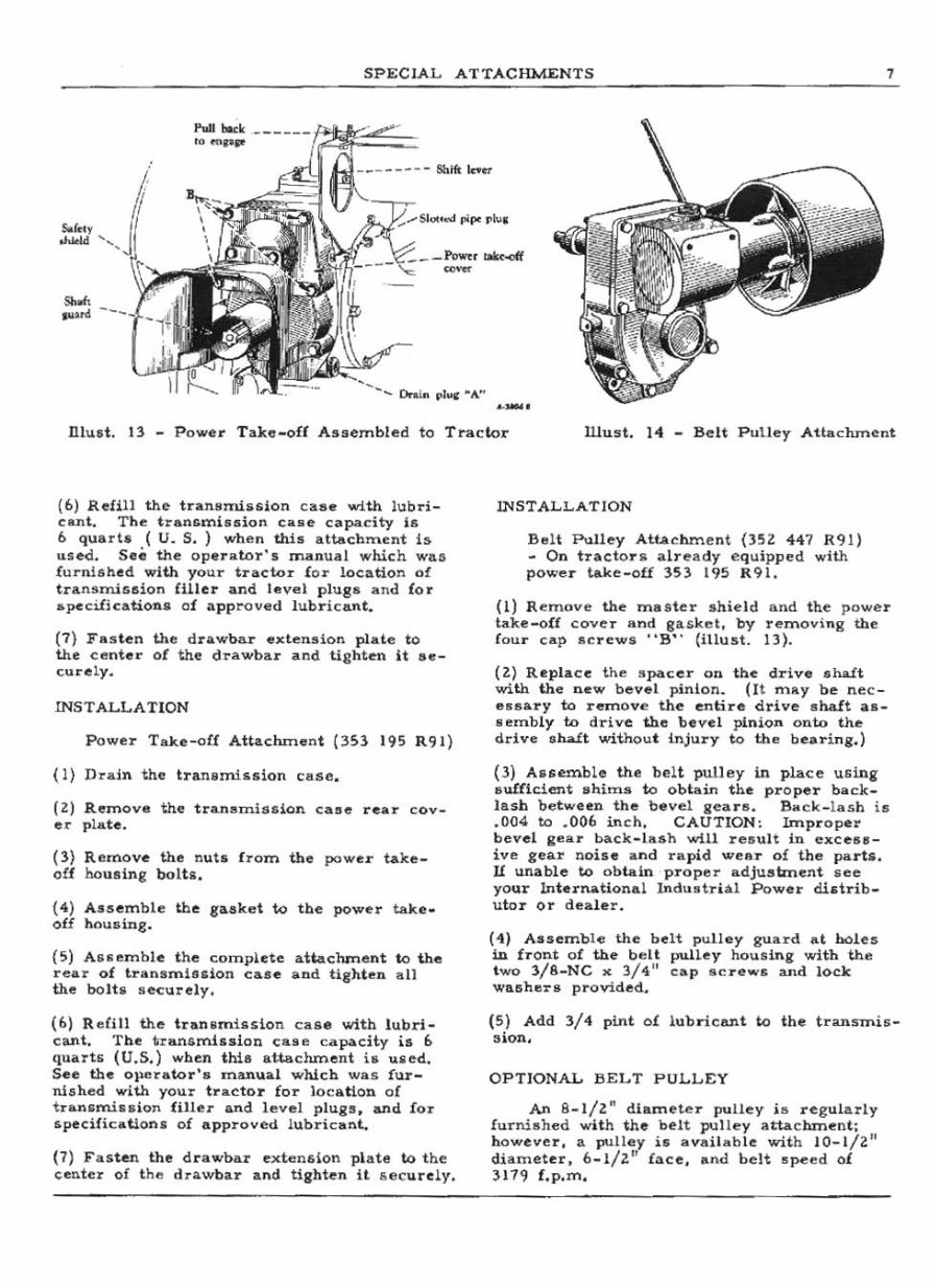
SPEC IAL ATTACHMEN TS , Sofe.y ..... Pull bo.ok _____ _ .0 ..... .,. , -- -~-- -~:: ........ Onl .. pl"" "A" ( 6) Refill the tranlllmilH.ion c aae with ll,lbri- eant. The tra.nsm.iuion calle capacity i& 6 quart. (u. S.) when this attac h ment is use.d. See the operator's mll . nual whic h was furnlah ed with yo ur tractor lor location 01 transmission HlI er and level plug_ and lor .. pccilic_tion a 01 appr ove d l ubricant. (1) Fas te n the dr awbar extension plate to the center oC the d rawbar lind ti ght en it _e - curely. INST ALLA TION Power Take-off Attachment (3S3 19 5 R9l) (l) Drain the tran .mi5sion case . (Z) Remove the t ran .. misdon cllse rear cov - er plate. (3) Remove the nut5 from the powe r take _ off Mus in g boltl, ( 4) A .semble the giUlk"t to the power take _ off housing. (S) Aruemble the complete a.ttachment to the r ear of tranunlulon case and tig hten sll the boIt5 securely. (6) R eCiIi the tran ~ mill$ lon case with lUbri- cant. The transm.hsion cage C;lpaeity is 6 quarts (U.S.) when thi s attachment i. ulled. See the ope rato r's manua l which was fu r- nished with your trao:':to:r for loca ti on of tran5misllion fill er and level plugs , and for specificaUons of approved lu bricant. (7) F as ten the d rllwbar e.xttm&ion plate to the center of t he H:-awbar and tishten it 6 l1l ClIorel y. Wu st. 14 - Belt Pull ey Attac hment INSTALLATION Belt Pulley Att&dunent ()SZ 447 R91) - On tract o rll alre a dy equipped wi th powe r t.ke - off )5) 195 R91, (I) Remove the ma st er shield and the powe r take-o!f cover and 8a5 k e~. by remov ing the lour cap Ae r eW$ "9" (i llust. 13). (Z) Rep la ce the sp.ac er on tb.e drive .ru.tt with the new heve l pinion. (It "''II'y be ne c- eUlllry to remov(! the entire drive .halt aA- RI!mbiy to dri.ve the bevel pinion onto th e dt'ive ... ha.£t without Injury to the bea ri ng.) (3) Auemble the belt pulley in place usin, Auf£1cient llhima to obtain the pr oper back_ las h bet .... een t he bevel geare. BlOck_l ash ill .004 to .006 in ch . CAUTION: Improper bevel .Ilea .. back- L ash will reBUlt in exceBB- ive gear noise ;a nd rapid wear of the paTtli. If unable to obtai n proper adjuabnent lI ee your International Indu str i al Power dilltrib _ uto r or dealer. (4 ) A.-semb le the belt pulley guard ILt bol es in front of the helt pulley housing with the t wo l/ 8-NC x 3/4" o:':ap .o:': .. e .... s and lock washers provided. (5) Add 3/ 4 pint of l ubri can t to the tran $mis- s ion. OP TI ONAL IIELT PULLEY AA 8-I/Z" diamete r pulley ja re gula.rly fur niahed with the belt pulley attac hment ; however, a pulley irs; availahle wit h 10-I/Z" di ameter, 6_1/Z" Cace, and belt s peed of )119 f,p. m.
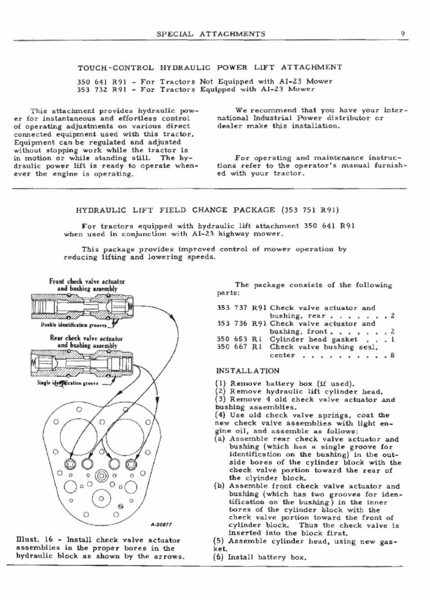
SPEClAJ.., ATTACHMENTS 9 TOU CH·CONTROL HYDRA UL IC POWER LIFT ATTACHMENT 350 641 R91 For Tn, c to~a Not Equi pped with AI.23 Mower 353 132: R9 1 • For Tr actor3 Equipped w ith AI. Z3 M ow"r Thi, attachment pro vid e .. hydr a uli c pow_ e r f or instantaneoull and .rro rtl e as co ntro l of o peratin g adjulltmrnt5 on var ious d lr ftct co nne c ted equipm ent u 5ed with this tr ac tor. Equipmen \ can be regulated an d adjusted wiU.<lut Ntopping w ork whil e the tractor Is in motion Or whih at endl nll s till. Th., hy- d raulic power lift is rcad y to o perate when - e ve r the "oai ne is operating. W .. r ecommend that you Mve your Inte .. _ n41tio nal Ind us t .. ial Pow e .. dl a tdb utDr Or de .. h ,r make t hill insta ll ation. For opera t ing and rnainl(:n.ance in.s tru c- tiona re fe r to th e ope rator' lI m an u al furnish - ed w ith yo ur t ...... : to ... HYDRAULI C LIFT FIELD CHAN CE PACKAGE (353 75 1 R9 1) FOT tra c t o .. s equipped with h ydIaulic lift atta c hIn e nt 350 641 R<;II whell uaed In conjunction wHh AI _23 hi ghway mowe ... Thii pac kall " provide " Unp .. oved contro l of mowe .. 0p"' Iat io n by reducing lilting and l owerins spe ed s. o II..JQ'" Dlust. 16 - lnlltall CMClt vll i ve actuator assembliei in ihe p,,"ope r bo .. ea in the hydTauHc blo ck "" ah own by the a IrOW I. The pac:kage conJEist!:; oC the following part5: 3.53 737 R91 C he c k .. alv e act u ator and bl.l"hin g, .. "'".. • . • . .. Z 353 736 R 91 Cheek va lv e actuator and bushing. fr o ot. • . • • • l 150 653 R I Cyli n der b",ad aa sket I 350 667 RI Chec k va l .. e bu s h i.ne seal , eenh: .. , . . . . , . . . 8 INSTALLATI ON ( 1) Remove ba Ue ry box (if u sed) . (Z) Ren'l o ve tlydr aulk l ift cy linder h",a d. (3) Ren'l ov (: <I old check valve ac tuator and bu shing &6 se mbH .II. ( 4) U6e o ld ch ec k va lve 6prhig" coa t the n ew c: heck v",lve a •• embli"a with Haht e n_ gine oil, and aca " rnb le .. , fo ll ows : ( a) A s""rbble ~eflr c heck va lve ac t uato r and bushing ( whi ch h . ... . It .. ingle groove for id enti fi cu J.on on the bushing ) In the out - .side bol'''' s oC t he cylinder bl oc k with th" cbeck vdve portion towa rd lhe rellr of the clyi,nder bl oc k. (b) Ass emble (r o nt Check valve actu a tor and buihin g (which h as t wo ar oov,," fo r ide n_ tifi c ation on the b Ullhing) In th e inner bor", .. or the cylinde r bl ock wi th the check v".i ve portion toward t he front of cyl1nd"r b lock . Thus the c he ck va.lve is lnsel'ted Into the block fI n t. (5) AS .!l l'!m b!e cy linde .. he ad , using n.,w gas- ket. (6) Insta ll battery bo x.
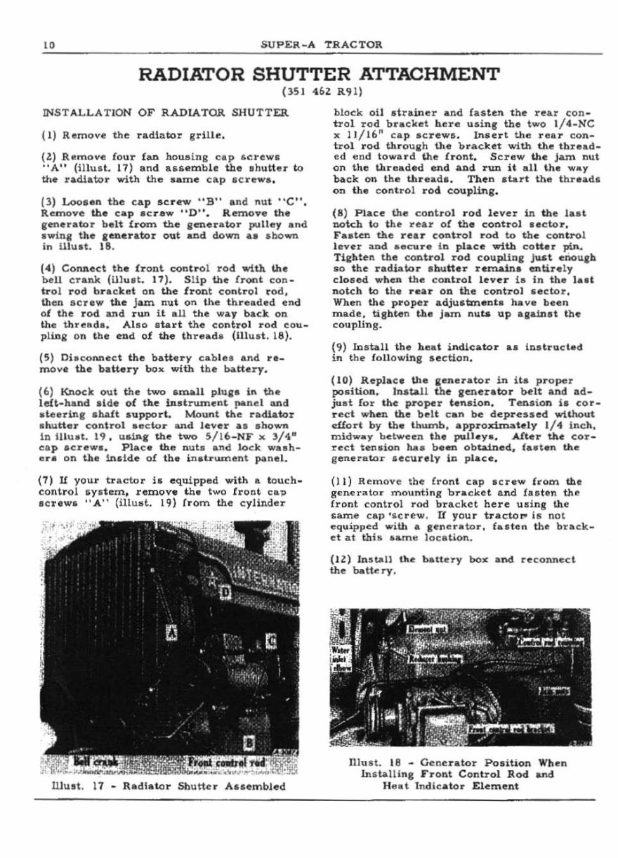
10 SUPER_A TRACTOR RADIATOR SHUTTER ATTACHMENT (lSI 46z R'H) INSTALLAT ION OF RADIATOR SHUTTER (1) Remove the radlato: grill e. (ll R"moYe lour flU) housing cap ~c rew . "A " (Utu.t. 11 ) and ."emb ie the .h utte .. to the radiator with the same Cltp acre"",., (3) Loo •• n tbe cap acre ... "B" and nut "C ". Remove th. cap acraw "D". R~o". th" ,tonerator belt !rom the generator pulle, and .winll the ,ellerator out aud down •• .boom in ilIu.t. 18. (4) Connect tb • .front <:ontl'ol rod with u... bell el'aNt (Ulult . 17 ). SUp the front con _ nol rod bracket on the fl'ont control rod, then scre w the Jam. nut on the threaded end of the rod and .. un it an the way hack on the thre .. d.. All o ata rt the control rod cou _ plina- on t he end of the thread .. (tUud. 18). (5) Oi.connect the battery cabl •• and r._ move the baUery box with the battery. (6) Knock out the two ,mal l pllli. In the left-hand ,Id. of the inatrwnent panel and au-Irin, shaft .upport , Mount the radiator .twtter control • .,dor and lever .... shown in lIIuat. 19, ualn, the two S/ 16_ NF x 3/4.- ca p ac rew a. Pla c. the o uta and lock w.... h- lira on the 1n51de ot the in.lr ....... en\ panel. (7) U your tractor i. equipped with .. touch . control ayatem, remove tha two troot cap lerlwa "A" (illu.~. U) trom the cylinde r black 011 drain.,r and falten t he rear con - trol rod bracket here us i n, the two I/"-NC x I I/16!' cap acrewe, In.ert the rea:.- eon - hOi rod throulI;h the l;tracket with the thread _ ed .,nd toward the bont , Screw th e jam nut on the threaded end _d run it all the way back on the thread.. Then start the thre ada on the con trol rod. couplin,. (8 ) Plaee the to nb ol rod lever in the I ... " not.ch to the rear ot the cODtrol lecto r, F .... ten the rear control rod to the c ontrol lever and. .ecu re h~ place with cott.r pin. Tilthten the control rod couplln, just enoueh 80 the radiator "h",tter remain, entire ly cl05ed when th" contro l lever 111 in the taat notch to t he r ..... r on the conh-ol .ector, When the proper adju.t:rnellta have been mllde , tiahlen the jam nuta up aaainet the coupHna· (9) Install the hnat incUeator &I Illstrueted in the lollowlng .ectlon , (to) Replace th e leDer ... tor in ita proper poailloo, Install the ,enerator bett &Ad ad- juat for the proper tanaioll, Tenaion loa cor_ rect when the belt can be depressed wHhout eUort by the thumb, approximately 1/ 4 Indl, midway between the puUey., After the cor_ rect ,en.ion hala been obtAined, fa"ell the generator £eeu raly ill place, (II) Remove the Cront cap .cr.w from the g",ne rdor mouni;ng b racket II.lId faetell th e frDnt control rod bu.ekct here u.illS the $lUT\e cap ' lIcre w. If your trac;toroo is not equipped .... ith a ,enerator , fa. ten the brack_ et ... t thi. lIame loca tion . (Il) Install tloe o-ttery 00., and re connect the battery. Dlu.t. 18 - Generator Position When In.llullln, Front Control Rod aIId He at IndIcato r Element
This is a comprehensive manual for the IH Farmall Super A Tractor, covering a range of special attachments designed to enhance its functionality. The manual provides detailed instructions on the installation, removal, and maintenance of these attachments, making it an invaluable resource for both professional mechanics and DIY enthusiasts.
The manual covers a variety of special attachments, including electric starting & lighting, belt pulley and power take-off, hydraulic power lift, radiator shutter, exhaust muffler, spark arrester, pre-cleaner, pre-screener, air pipe extension, wheel weights, adjustable front wheel, swinging drawbar, and pintle hook.
With clear and easy-to-follow instructions, this manual is suitable for individuals with varying levels of mechanical expertise. It is also searchable and bookmarked, allowing users to quickly access the information they need. The manual is available in easily accessible file formats, enabling viewing, zooming, and printing on any computer.
By owning this manual, users have the flexibility to access and print the necessary information at their convenience, eliminating the need for costly external printing services. For immediate access to this invaluable resource, simply click the designated button on this page.
For any inquiries about additional manuals, feel free to email us. This manual is a must-have for anyone looking to optimize the performance of their IH Farmall Super A Tractor with special attachments.
Recently Viewed
5,521,897Happy Clients
2,594,462eManuals
1,120,453Trusted Sellers
15Years in Business
Price:
Actual Price:
Farmall IH Super A Tractor Special Attachments Owners User Installation Manual -