

IH Farmall F-20 Tractor ILLUSTRATED Parts & Owners Instruction -2- Manuals -
What's Included?
Fast Download Speeds
Online & Offline Access
Access PDF Contents & Bookmarks
Full Search Facility
Print one or all pages of your manual
Examine the traclDr carefully anti see that all oil hole3 are cleaned
of paint anti tlirt-if any IhrtlltleJ oil holel are found with no grea3e
or pipe connections, loolc td the Lubricdi.ion Chart. If connection ;3
.houm, and nol In place, It ..... 1011 and .hould be replaced before
3tarting.
Special Precautions with a New Tractor
1. Before starting a new engine, remove the spark plugs and put about one ou nce
of gas engine lubricating oil into each cylinder; replace the spark plugs and crank
the engine to distribute the oil over the .cylinder walls.
2. 'Vhen cranking an engine. the operator should take his position so as to avoid
being struck by the starting crank if there is a reversal of the direction of the engine
from any cause whatsoever.
3. During the first one hundred. hours of operation, mix one pint (If engi ne oi l with
every five ga ll ons of fuel.
4. See that the engine has the proper amount of oil in the crankcase.
5. See that all lubrication connections are filled with lubri cant approved for use in
Alemite-Zerk compressor. (See "L ubri cat ion Ch art" for Specific-ations.)
6. See that oil in tran s mi ssion is up to level of plug located in frollt of transmission
case. (See "Lub rication Cha rt .")
7. See tllat oil in rear axle carrier is up to level of plug located on sid e of ca rrier.
(See "L ubrication Chart.")
8. See that oil in steering gear case is up to level of pl ug located 011 siue of case.
(See "Lubrication Chart. ")
9. See that oil in oi l air filter is up to proper level.
10. Tractors shipped Domestic and Canada are properly filled with oil in all
parts when shipped fr om the factory. All oil i3 drainedfr om tractors 3hipped Export.
However. Tra ctur should be checked over for proper quantities of oil before sta rting.
It. Complet e instruct i ons for oil in g are sho wn on "Luhri cat ion Chart ."
12 . Do not operate a new Tractor on/ullioad. The Tractor should never be loaded
to full capacity until it has heen run light for a reasonable l ength of time. After
oiling and luhricating, the tract or, for the jir3t 50 hour3, should he run at half load
or Ics:J befoTe it ;$ put on /ulllooJ.
13. Modem trac to rs travel fa st, therefore due care should be exercised in gett in g on
or 01T the tracto r, to avoid acc ident or injury to the operato r.
14- . \rh en starti ng the Tractor aiuJaY3 engage the clutch gradually so the engine
will pi ck up the l oad slowly. Thi s is particularly necessary when the tractor is
going up a steep hill, climbing o ut of dit ches or when hitched to some heavy or.
diffic ult load. Never hitch a tra c tOr to a stump or other object by means of a
long chain or rope witll slack so that when the tra cto r moves forward it will jerk
into the load.
15. Reatll n:Jtruction Boo~ carefully.
' Ordering Repairs
\\'h en ordering repairs he sure to give Serial Number and Model of Tractor and
name and number of Part Ordered.
Thi s book contains, in addition to instructions for operatin g, in str uctions and
illustrations pertaining to certain simple adjustments and replaceme nts which
can readily be made. However, the owner should consult the service dealer before
atte mpting a general overhauling or when any mechanical difficulties occur, as he
has the necessary equipment for doing the work.
Specljicol.ioru ""ill k found on IruiJe 6ac4o: co«r.
For Lis( of Paris onJ Sedlonal VlelDs • • ee pa,a 31 to 76.
"' uel
'.nA:
. ,,.ap
F,u ,'
,."Ie
"' "u ll
'0"A:
~p
C ..... line
'.nle rap
,
no,en-cold
11 _, co,., ,.ol nond ,_,.
(Znd-tn, er m edi .. l.
F" .,I pipe
(' 0
_,.bur .. ' .. ,. )
Ke,. ... e .. ..
_" .. , ... jf
, ... h, ,,"
\
" ,,.ai,, e,.
"'".,1 pipe
(6· .... ,." ..
'flnA: 10
.t,...i"er)
Illustration No. 1
po .. i,io" !
.. , no,e n-ho t
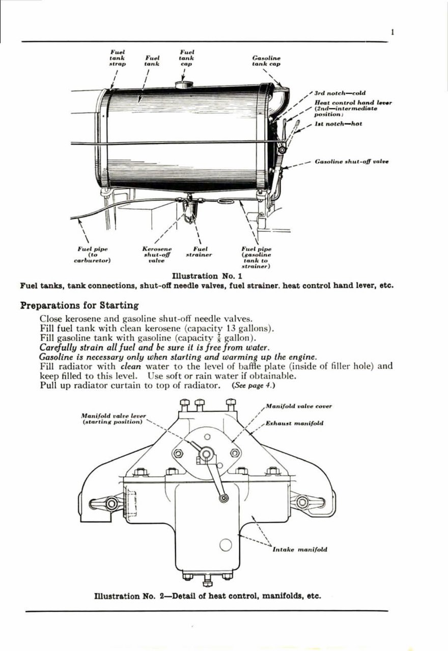
Fuel tanks, tank connections, shut-of! needle vaivell, fueilltrainer . heat control hand lever, etc.
Prepa.ra.tions for Starting
Close kerosene and gasol in e shut-o fT needle valves.
Fill fu el tank with clean kerosene (capac it y 13 gallons).
FiJ I gasoline tank wi th gasoline ( ca pacity 7 gallon ).
Carefully 3train all fuel and be 3ure it i3freeJrom water .
Ga 30 line i3 nece33ary only when 3tarting and warming up the en gi n e.
Fi ll rad i ato r with cl ea n water to the level of baffle pl ate (in side of fill er hole) a nd
keep filled to this level. Use soft or rain wate r if o btainable.
Pull up radi ator c urtain to top of radi ato r. (See page 4.)
M."ifold ,·.I , '4t Ill ': '"
(d ar, ;n, ,,,,'; 11,,, ,) ' ...
--
o
/,\ta" ij .. 1d .,.,1".. C ... 'f!"
/
,/ ... &1 ".,0. ' ... ... i/ol. 1
..
,
\
,
... -...... '.
--4
o
Inl. nA: .. manifold
Illustration No. 2-Det.ail of h eat control, manifolds, etc.
2
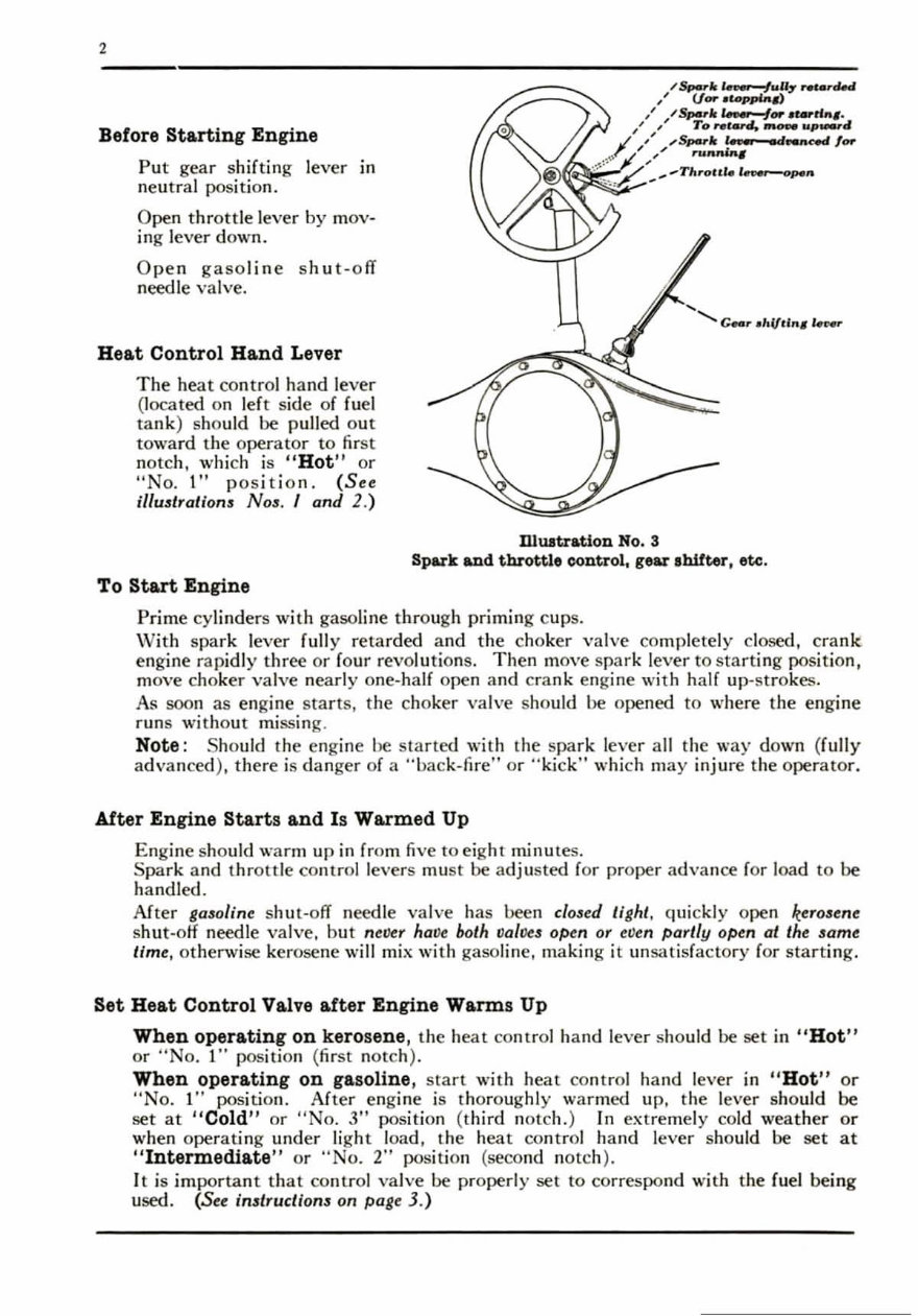
Before Stming Engine
J~
Put gear shifting lever in
neutral position.
Open th rottle lever by mov-
ing lever down.
Open gasoline s hut-off
need le va lve.
Heat Control Hand Lever
The hea t con tro1 hand lever
(loca ted on left si de of fuel
tank ) should be pulled out
toward th e operator to fir st
not ch, which is " Hot " or
"No. 1" po s it io n. (S ee
iIlu.s tralion .s NO:J. I and 2.)
To St&rt Engine
D.Iuatration No.3
Spar k. and throttle control, gear ,hitter . etc .
Prime cylinders with gaso li ne thr ough priming c ups.
\ ¥it h spa rk lever f ull y re tarded a nd the choker va lve co mp l ete ly close d, crank
engine rapidly three or fo ur revolutions. Th en move s park lever rostarti ng position,
move choker valve nearly one-half open and crank engine with haH up-s tr okes.
As soon as engine st arts , the choker valve should be opened to where the engin e
r un s without missing.
Note : Should the engine be st arted with the spar k lever a ll th e way down (full y
advanced ), there is danger of a "bac k-fire" or " ki c k" which may injure the operato r.
Aftor Engine Storts and Is Warmed Up
Engine should warm up in from fiv e to eight minute s.
Spa rk and thrott le co ntrol levers mu st be a dju sted for proper advance for load to be
handled .
After g030 iine s hut- o ff needle valve has been cl03Cd ti ght , quic kl y open kero3en e
shut-otf needle valve, but n elle r ha ve both lJal lleS open or elle n partl y open at the same
lim e, othenvise kerosene wi ll mix with gasoline, making it un sc Hisfactory (or starti ng .
Set Heat Control Valve after Engine Warms Up
When operating on kerosene, the heat control hand lever should be set in " Hot "
or ;;No. t" position (first notc h).
When operating on gasoline, sta rt with heat co ntrol hand lever in !l Hot " or
"No. t" position. After engine is thoroug hl y war med up, the lever sho ul d be
set at H eold " or "No.3" position (third notch. ) In extremely cold wea th er or
when ope rati ng under lig ht load, the heat con tr ol hand l ever should be set at
II Intermediate " or ., No.2" position (second notch ).
It is important that co ntrol va lve be properly set to correspond with the fuel being
used . (See instruclion3 on pogt 3.)
To Start Tractor
Pl ace left foot on cl ut ch pedal and press down firmly,
hol ding in this position ; this disengages the cl utch. Clutch
mUll always be cliscngagecl while shifting gcars.
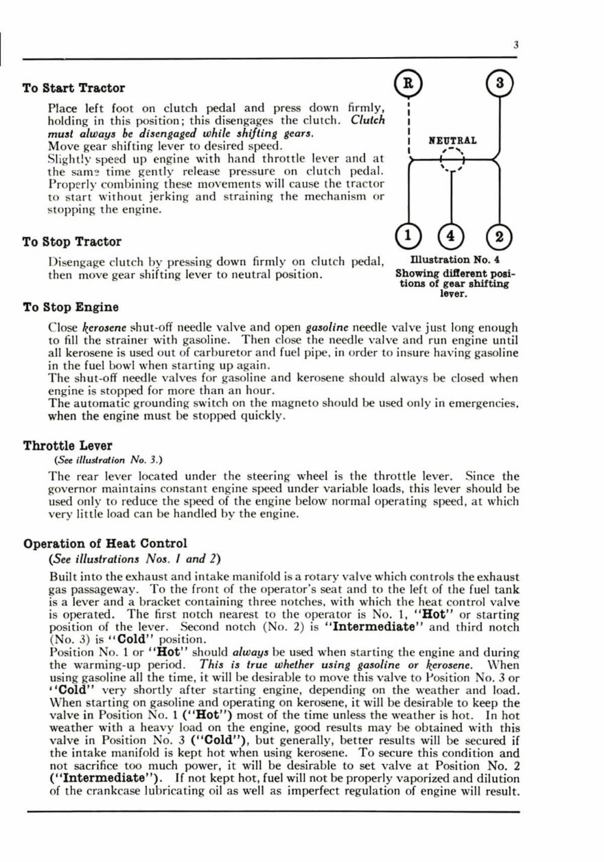
M ove gear shifting lever to desired speed.
Slig hd y speed up engine with hand throttle l eve r a nd at"
the sam !!: time gently relea se pre:;s ure on clutch pedal.
Properly co mbi ni ng these moYements will ca use the tfa c tor
to sta rt with o ut j er king an d st raining the mecha ni sm Or
s toppi ng the engi ne.
To Stop Tractor
Di sengage cl ut ch by pressing down firmly on cl utch pedal,
then move gear shifting l ever to neutra l position.
To Stop En gi ne
lI'EUTRAL
,-,
'. ,
3
Dluatration No. 4
Showing diflerent pOIi-
tiona of gear shifting
lever.
C lose kc r o3e ne !Ohm -off need le va lve a nd ope n gaso line needle va lve ju st long enough
to fiJI the st rainer with gasoline. Th en cl ose the needle valve and run engine until
all ker osene is used o ut of ca rbur etor and fuel pipe, in o rder to ins ur e hav ing gasoline
in the fuel bowl wh en s tartin g up again.
The s hut -o ff needle val ves for gasoline and kerosene should always be closed when
engine is sto pped for more than an ho ur .
Th e au tomatic grounding s wi tch on the ma gneto should be used o nl y in emergencies,
when the engine must be stopped quic kl y.
Throttle Le.er
(See illustration No .3. )
Th e r e.: 'lr lever located und er the steering wheel is the th rott le lever. Since the
governor ma in tains consta nt engine speed und er var iable l oa ds. this l eve r sho ul d be
used o nl y to reduce the speed of the engine below normal operat in g speed, at wh ic h
very lillie l oad ca n be handled by the engine.
Operation of Heat Control
(See illustrations Nos. I and 2)
Built into the exhaust an d intake manifold is a rot ary valve which contro ls the exhaust
gas passageway. To the front of the operator 's sea l and to the le ft of the fu el la nk
is a l eve r and a brac ket co nt ai ning three notc hes. with which the heat co ntro l valve
is ope rated. Th e fir st notc h nearest to the operator is No. I. " Hot " or s tart ing
position of the lever. Second notch ( o. 2) is " Intermedia.te " and third notch
(No .3) is " Cold " position.
Position No. 1 or I' Hot " should always be used when sta rting the engine and during
the warming- up pe ri od. This is true whether usin g ga~lOline or kerosen e. Vlhen
using gasoline a ll t he time, it will be desirable to Ill ,ove this valve to Position No.3 or
" Cold " ver y short ly after sta rt ing engine, depending on the weathe r and l oad.
\OVh en sta rtin g on gasoline and operating on kerosene, it will be desirable to keep the
va lve in Position No .1 (" Hot") most of the tim e unless the weat her is hot. In hot
wea ther with a hea vy l oad on the engine, good res ult s m ay be obtained with this
valve in Position No. 3 ("Cold") . but genera ll y. better res ul ts wi ll be secured if
the in take ma nifold is kep t hot when usi ng kerosene. To secure this co nditio n and
not sacri fi ce too much power, it will be desirable to set valve at Position No .2
("Intermediate " ). If not kept hot, rue l wi ll no t be prope rl y vaporized and dilution
of the cra nkcase lubri cat ing oil as we ll as imperfect regulation of engine wi ll result.
4
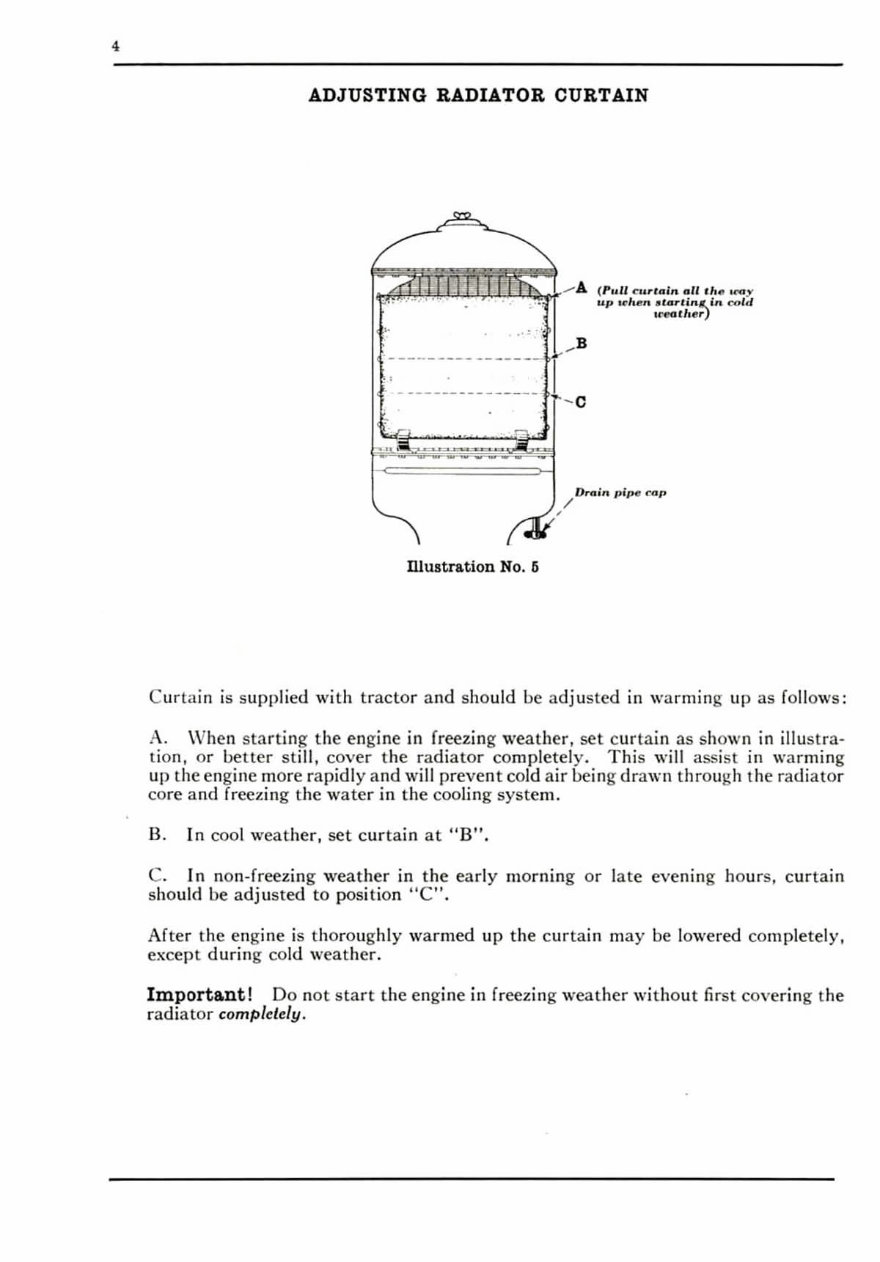
ADJUSTING RADIATOR CURTAIN
,.
. ,
~-=---'--=--"""""'-""'-
-~~
illustration No. fj
I
~B
-c
/
Or .. in , J'pe f:Qp
Curta in is suppl ied wi th tractor and should be a dju ste d in war min g li p as fo ll ows :
A. \ Vhe n sta rting the engine in freezing weat her, set c urt ai n as shown in illustra·
lion, or beller still, cover t he rad iator completely. Thi s will assi st in warming
up the engine more rapidly and will prevent cold air being drawn thr ough t he radi ator
core and freezing the water in the cooling system.
B. In cool weat her, set cu rt ain at "8" ,
C. In non-freez in g weather in the ea rl y morning or late eve nlllg hours, c ur tain
should be ad justed to position "C" ,
After the engine is thoroughly warmed up the curtai n may be lowered cO lllpletely,
except during cold wcather.
Important! Do not s tart the engine in freezing weather wi tho ut first covering the
radi ato r completely.
Oil
_ -.- "tra in",.
"iiiii!'.- Oi l fi ll er
~ ----- , ,,,.
G .. ~r"o'
_ ..... - .. J,i~lll
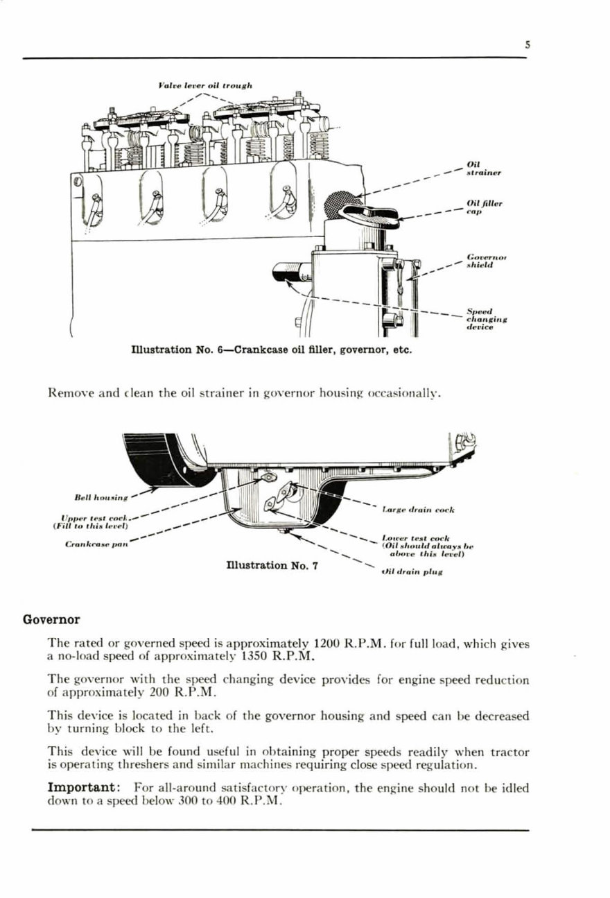
nlustratioD No. 6-Cra.nkcase oil filler, governor, etc.
Remove and dean the oil st rainer in governor hO ll s in g occasionally.
11., /1 '''''''';'' 1'
- - _ , .. " ....., , .. ,, ' C<N'k
....... - < Oil "1 ... ,,lfl o,.My. I .. •
................... ~ ab. .. · .. ,I,i . '" .... /)
Dluatration No.7 -..
.,lil d,,. i ,, "/" ,,
tT,.,,, · ,· !' : ... n"·~ ,'- -
( I'illl"
--
--
--
-- Cu l/,kra .... ' ... "
,.
Governor
s
Th e Tated or governed speed is a pproximately 1200 R.P.M . for full loa d, whi ch Rives
a no- load speed of ap proximately 1350 R.P.M.
Th e gO\'crnor with the speed changing device provides for engine speed reduction
of approx imately 200 R.P.M .
T his dev i ce is located in back of t he govern or housi ng and speed can be decreased
by turning block to the left.
Thi s device will be found useful in obt aining proper spt.>c<ls readily whe n tra ctor
is operating threshers and simil ar machines requiring close speed regulation.
Important : For all·aro und satisfactory operat ion, th e enJ,!"i llc should not be id led
down to a speed below 300 to 400 R .P .M.
6
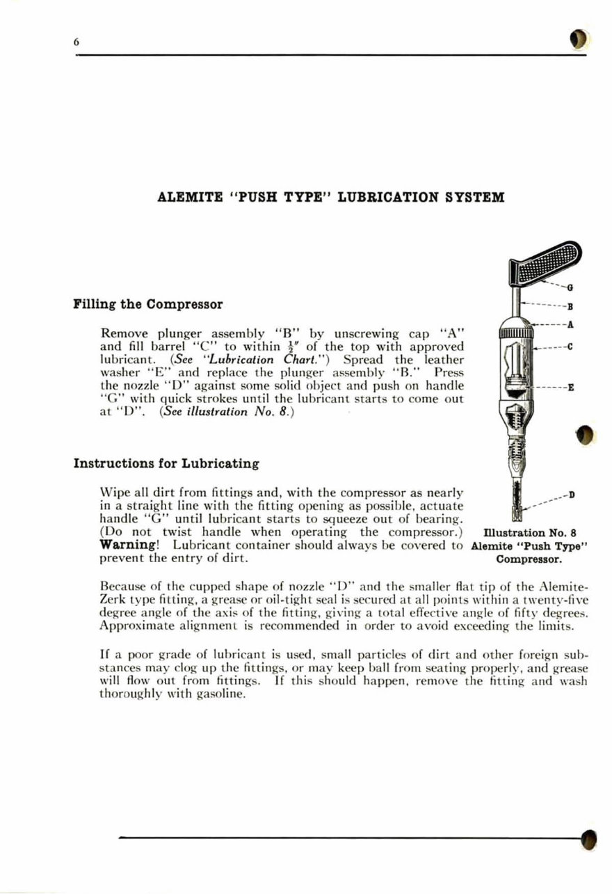
ALEMITE "PUSH TYPE " LUBRICATION SYSTEM
Filling the Compressor
Remove plun ger assembly "B" by unscrewing ca p "A "
a nd fill ba rr el "e" to wi th in l" of the top with a pproved
lubri ca n t. (See "Lubrication Chart .") S prea d the l eat her
was her " E" a nd re pl ace the plunger assembly " B," Press
th e nozzle "D " aga in st some solid object and push 0 11 handle
"C" wi th q ui ck strokes until the lubrica nt starts to co me O llt
at "0 ", (See i/lu3trati on No. 8.)
Instructions for Lubricati ng
Vlipe a ll dirt from fittings a nd , w it h th e co mpressor as n ea rl y
in a s traight line wi th the fitting opening as possible. act uate
handle " G" unt il lubri ca nt star ts to SCI" ce ze O ll t of bear ing.
(Do n ot twi st handle when operati ng th e compressor.)
Warning ! Lu b ri ca nt con tainer should always be covered to
preve nt the entry of dir t.
mustration No.8
Alemite "Push Type "
Compressor.
Beca use of the c li pped shape of nozzle " ))" an d t he smaller A at tip of the Ale mi lc -
Zerk type fitt in g, a greasc or o il-ti ~dll seal is secured at a ll poi Ill s wit h in a twc ll ty-fi,'e
de~ree a ngle of the ax i ~ of the fitt in g. giving a L ota l effecti\'c angle of fifty degrees,
Approximate a li g nm ent is recommended in order to avo id ex ceedin g the li mits,
If a poor gr ade of lu br i ca nt is lI sed , sma ll p art icles of dirt a nd oth er foreig n s ub -
sta nces may clog up tJl e fittings, Or Ill ay keep ba ll from seating properly, and g-rease
will Aow out fr0 111 fitt ings, If t h is should ha ppen, remove t he li lt in g and wash
th o rOuKh ly with ga~olille,

7
Engine Lubrication
Th e life and e ffi cient wor king of the engine depends on proper lub ri cation ; neg lect
in t hi s dir ec ti on may cause serious trouble, excessive wear and co mpl ete brea kd own .
Prope rl y oiled working parts mu st a lways have a t hi n film of o il be tween them;
the kind of o il to use und er a given condi tion is d eter min ed by its ab ility to establish
t hi s film be tween the rub bing parts. and to resist being squeezed out under normal
press ur e. It must also be of proper qu a li ty to resi st decomposition caused by heat.
Th e average ope rator does n ot know th at to get the ma ximum horse power from
hi s tr ac tor he mu st look a fter hi s lub ri cat ing oil as closely as he does hi s fu e l. The
best o il that can be obt a ined will wea r o ut a nd become g ri tty in time.
Too much cannot be said about th e need of good o il of the proper body . O il which
is s ui tab le f or lub ri cation of in te rnal combu stion engines must be neutral -that is ,
free fr0 111 acid or alkali reac tion; free fr0 111 moist ure, t ar ry or suspended maHe r;
mu st have fl O thickeners or min eral in suspension.
Engine oiling is very impo rt ant and in st ru ct ions should be fo ll owed cl ose ly.
Cy linders, co nnecting rods, cra nkshaft bearings. camshaft, and a ll par ts wi thin
the cra nkcase are lubricated by splash.
iEngine Oil Supply
Th e oi l must be poured ilHo the crankcase sump through an opening for t hi s purpose
l ocated on the governor housing at the front of the engine. (See illu3lration N o. 6.)
If poured in t hr ough the han d holes, govern or p arts will not be su ffic iently lubri-
cated. T wo test cocks are locaced on che right side of the cra nk case pan wh idl
indicate the h ig h and low level of the oil. T he oil should never be above the high
level nor below the low leve l. (S ee illu3iralion No. 7.)
Oil Pre ss ure Gauge
Th e ind icator pointer in oil pressure gauge (unless defective) should regi ster at all
times wh en the engi ne is runni ng. . 'hould the gauge not register. it is an indiC<'ltion
that the o il pump is not performing properly Or the o il sup pl y need s renewing. Th e
engine should be SLO pped immedi ate ly and the oi l s yste m in specte d to fi nd the ca li se
of fa ilu re.
Transmis sion Lubricat ion
Th e transmission and final gears. in cl ud in g di ff erential and a ll b ear in gs f or lhe
transmission, are o il ed auto matica ll y.
It 3hould not be nece33ary to add lubricant to tran3mi33ion oftener than once a $e a3 0n
un/eu exceuif)e leaka ge occur3 30mewhere. or in ca 3e of accident, cau3 in g 1 033 of grea3e.
8
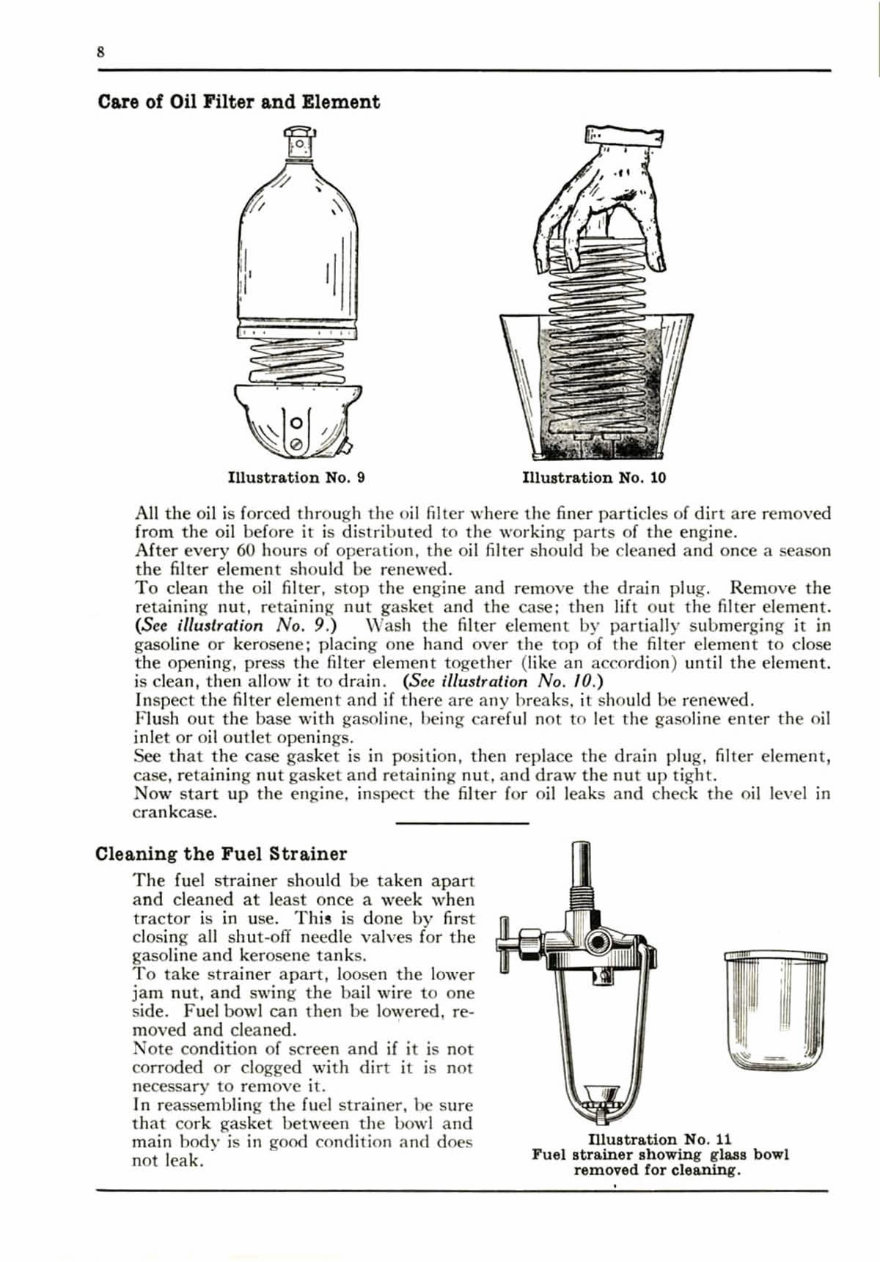
Care of Oil Filter and Element
llIustra.tion No.9 Illustra. tion No. 10
All the o il is forced through the o il filter where the finer particles of d in are removed
from the oil before it is di strib ut ed to the working parts of the engine.
After every 60 ho urs of operat ion, the o il filter sho uld be cleaned and once a season
the filter element should be renewed.
To clean the o il filter. stop the engine an d remove the drain plug. Remove the
reta ining nut, retaining nut gasket a nd the case; then lift our the filter el eme nt .
(See illustration No.9.) \Vash the filter element by partially submerging it in
gasoline or kerosene; placing one hand over the top of the filter ele ment to close
the opening, press rhe filter element together (l ike an accordion) until the eleme nt.
is clean , then a ll ow it to d rai n. (See iIlu3lration No . 10.)
Inspect the filter el ement and if there are any hreaks. it should be rene wed.
Fl ush out the base with gaso li ne, being c;"Iref ul not to l et the gasoline en ter the oil
inl et or o il outl et ope nings.
See th at the case gasket is in position, then repl ace the drain plug, filt er element,
case , retaining nut gas ket and retaining nut , and draw the nut up tight.
No w s tart up the engine. in spect the fi l ter for o il leaks and check the oil level in
c rankca se.
Cleanin g the Fuel Strainer
The fuel strain er should be ta ken apart
a nd cleaned at least once a week when
tractor is in use. This is done by fir st
closing a ll s hu t-off nCLodie valves for the
gasoline a nd ker osene tanks.
To take strainer apart, loosen the lower
jam nut, and swing the bail wire to one
side. Fuel bowl can then be lowered, re-
moved and cleaned.
Note condi tion of scree n and if it is nOt
corroded Or clogged with dirt it is not
necessary to rem ove it.
In reassembling the fuel st rainer . he sure
th at co rk gasket between the bowl and
main body is in good condition and does
not leak.
Illustra.tion No. 11
Fuel st ra.iner showing glas s bowl
removed for cle&ning.
You're Reading a Preview
What's Included?
Fast Download Speeds
Online & Offline Access
Access PDF Contents & Bookmarks
Full Search Facility
Print one or all pages of your manual
$52.99
Viewed 14 Times Today


Secure transaction
What's Included?
Fast Download Speeds
Online & Offline Access
Access PDF Contents & Bookmarks
Full Search Facility
Print one or all pages of your manual
$52.99
- This set includes two manuals for IH Farmall F-20 Tractor: an Instruction Owners Manual and a Parts Manual Catalog.
- The manuals provide detailed instructions for maintaining and servicing the tractor, including diagrams and specifications for Regular, Narrow Tread, and Fairway tractors.
- The Instruction Owners Manual covers maintenance procedures, lubrication, special attachments, specifications, and operating the tractor.
- It includes detailed illustrations, exploded diagrams, drawings, and photos to guide through service repair procedures.
- The Parts Manual Catalog contains a complete list of parts with exploded views, diagrams, part numbers, and descriptions, categorized into groups such as Engine, Wheels, Fuel System, and more.
- Both manuals are fully bookmarked, searchable, and indexed for easy navigation.
- They are ideal for both professional mechanics and DIY enthusiasts, providing technical details and step-by-step instructions for tune-ups, regular maintenance, and troubleshooting.
- The manuals are compatible with Win/Mac and can be viewed, zoomed, and printed on any computer.
These manuals are essential resources for anyone involved in the restoration or maintenance of IH Farmall F-20 Tractors.


