International Harvester 786/886/986/1086 Tractors OEM Service & Repair Manual
What's Included?
Lifetime Access
Fast Download Speeds
Online & Offline Access
Access PDF Contents & Bookmarks
Full Search Facility
Print one or all pages of your manual
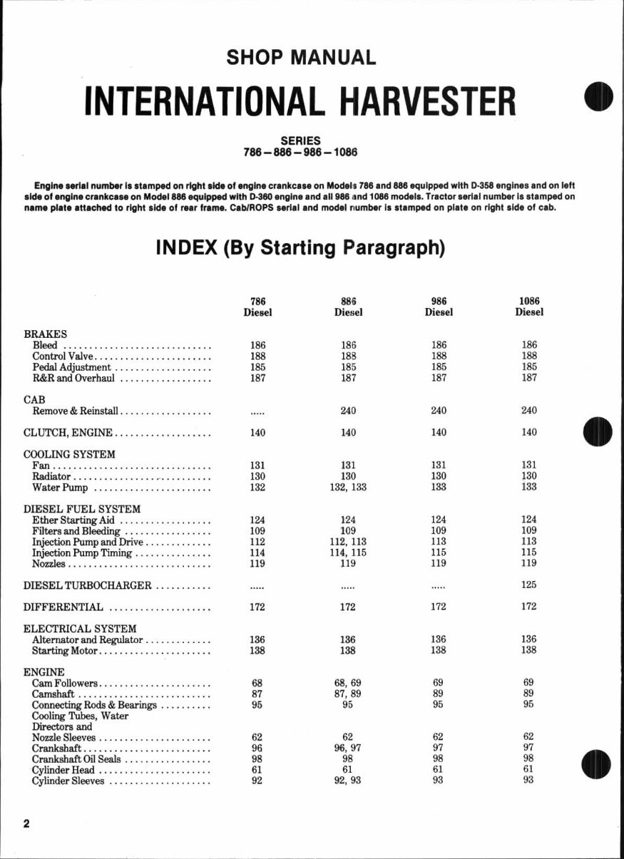
HOW TO USE THE INDEX: Suppose you want to know the procedure for R&R (remove and reinstall) of the engine camshaft. Your first step is to look in the index under the main heading of ENGINE until you find the entry “Camshaft.” Now read to the right where under the column covering the tractor you are repairing, you will find a number that indicates the beginning paragraph pertaining to the camshaft. To locate this wanted paragraph in the manual, turn the pages until the running index appearing on the top outside corner of each page contains the number you are seeking. In this paragraph you will find the information concerning the removal of the camshaft.
SHOP MANUAL INTERNATIONAL HARVESTER SERIES 788- 888 -986 -1086 Engln ....... 1 number I, .t.m~ on right ,Ide of engln. cr.nkc ... on Model. 786 and 886 equipped with 0-3S8 angln •• and on reft aide of .ngln. c,.nkc ... on Model aae ~ul~ wit h D-380 .ngln. and .11988 and 1088 moderl. Tractor •• rI.1 number I •• IImped on n.m. pI.l. ,«acMd to r'Vht .JOt 01 re.r fra.".. CabiROPS .. rial and model number II at. mped on pllte on right ,Id, of cab. INDEX (By Starting Paragraph) 786 SS. 98. 108. Diesel Diesel Die sel Diesel BRAKES Bleed . .. . . . . . . .. .. . . . . . .. . . . . . . . . . 1 88 18. 186 186 Control Valve ............ ....... .... 1 88 188 188 188 Pedal Adjustment . .................. 1 85 185 185 185 R&R and Overhaul ...... ..... . ...... 1 87 187 1 87 1 87 CAB Remove & Reinstal l. ................. 240 240 240 CLUTCH, ENGINE ................... 140 140 140 140 COOLING SYSTEM Fan ..... .............. _. _ . ........ 131 1 31 131 13 1 Radiator . ............... ~ .......... 180 130 130 130 Water Pump . . . . .. . . . . . . . . .. .. .. . . . 132 132, 133 133 133 DIESEL FUEL SYSTEM Ether Starting Aid . .. ............... 124 1 24 124 124 Filtors and BleedIDg .............. . .. 109 1 09 109 109 Injection Pump and Drive . ............ 112 112. 113 113 118 Injection Pump Timing . .............. 114 114. 11 5 115 115 Nozzles ........................... . 119 119 119 119 DIESEL TURBOCHARGER ......... •. 125 DIFFERENTIAL .. ............... ... 172 1 72 172 172 ELECTRICAL SYSTEM Alternator and Regulator . ..... ... .. .. 136 136 136 136 Starting Motor . .............. ..... .. 1 38 138 138 1 38 ENGINE Cam Followers . ..................... 68 68,69 69 69 Carnahaft ...................... •... 87 87. 89 89 89 Connecting Rods & Bearings .......... 95 95 95 95 Cooling Tubes, Water Directors and Nozzle Sleeves . ................. . ... 62 .2 62 62 Cnmbhaft ..................... • .•. 96 96,97 97 97 Crankshaft Oi l Seals ............ ..... 98 98 98 98 Cylinder Head ................. ..... 61 61 61 61 Cylinder Sleeves .................. .. 92 92,93 93 93 2
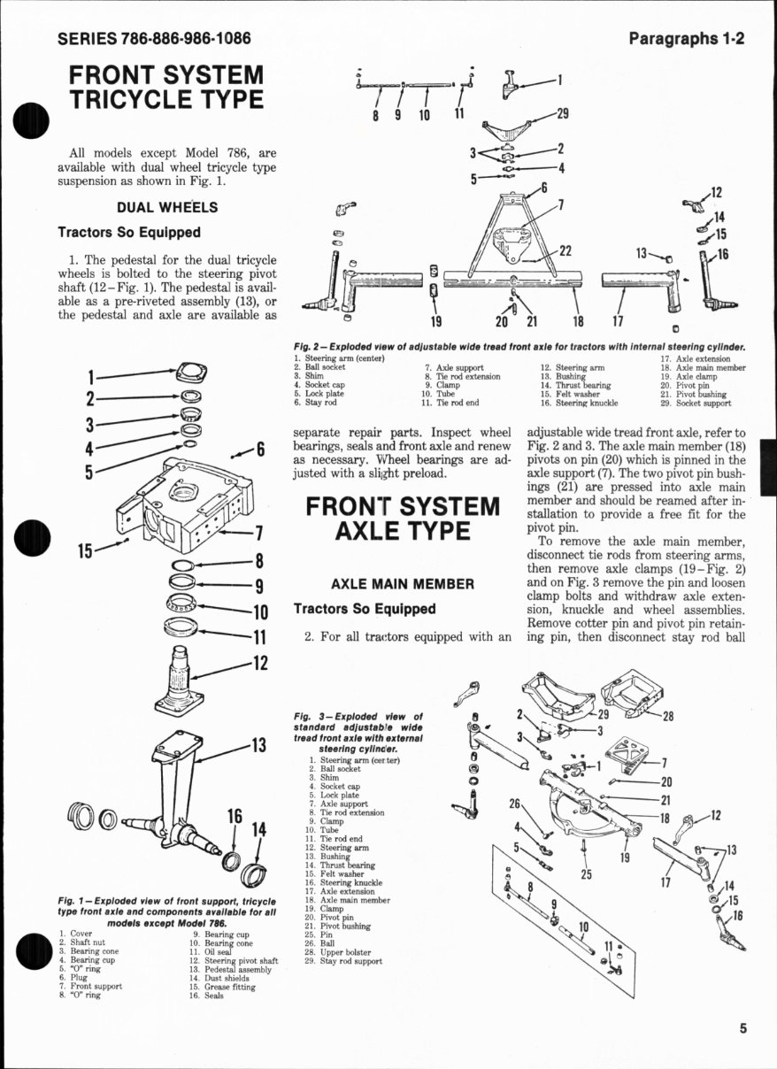
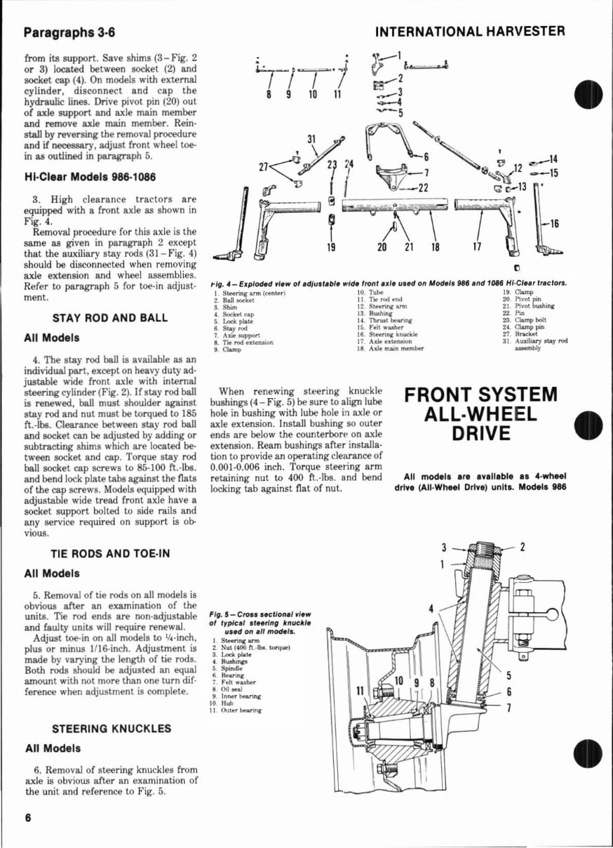
Paragraphs 3·6 from its support. Save shims (3-Fig. 2 or 3) locat.ed between socket (2) and socket cap (4). On models with external cyli nde r, di sconnect and cap the hydraulic lines. Drive pivot pin (20) out of axle support and axle main member and remove axle main member. Rein- stall by reversing the removal procedure and if ne<:e86Ilry, adjust front wheel toe- in as outlined in paragraph 5. HI ·Cle.r Models 988-1086 3. High clearance tracto rs are equipped with a front axle as shown in Fi g. 4. Removal procedure for this axle is the same as given in paragraph 2 except that the auxiliary stay rods (31 - Fig. 4) should be disconnected when re mov ing axle extension and wheel assemblies. Refer to paragraph 5 for toe-in adjust- ment. STAY ROD AND BALL All Modol. 4. The stay rod ball is available as an individual part, except on heavy duty ad- justable wide front axle with internal steering cylinder (Pig. 2), If stay rod ball is renewed, ball must shoulder against stay rod and nut must be torqued to 185 ft.·lbs. Clearance between stay rod ball and socket can be adjusted by adding or subtracting shims which are located be- tween socket and cap. Torque stay rod ball socket cap screws to 85·100 ft.·lbe. and bend lock plate tabs against the flats of the cap screws. Models equipped with adjustable wide tread front axle have a socket support bolted to side rails and any service required on suppo rt is ob- vious. TIE RODS AND TOE·IN All Modols 5. Removal of tie rods on all models is obvious after an eltaIllination of the units. Tie rod ends are non·adjustable and faulty units will require renewal. Adjust toe-in on all models to 1f 4·i nch. plus or minus IIIG-i nch . Adjustment is made by varying the length of tie rods. Botll rods should be adjusted an equal amount with not more than o ne turn dif· fe rence when adjustment is complete. STEERING KNUCKLES All Models 6. Removal of steering knuckles from axle is obvious after an examination of the unit a nd refere nce to Fig. 5. 6 INTERNATIONAL HARVESTER r- \~ . ~,"'.l ~2 ...- 3 ~ ~-5 31 f\- " 21 ;:::; ' 3\ {/14 ~ 6 '~ ~ 12 _ 14 '/' 21 I - J ~ .... "t( - -15 (I' I ( - 22 '" 0- 13 ~ f ~;~~ ' 16 ~ 19 20 21 18 1\ ~ When renewing steering knuckle bushings (4 - F ig. 5) be sure to align lube ho le in bushing with lube hole in axle or axle extension. In stall bushing so outer ends are below the counterbort~ on axle extension. Ream bushings after installa· tion to provide an operating clearance of 0.001·0.006 inch. Torque steeling arm retaining nut to 400 ft..-l bs. snd bend locking tab against fla t of nut. FIg. 5- CIOn l .el/oll.' , /s.., 0' I,ples' "NtllI" kIIud ls lI. ed 011 .11 model .. I s...... u.c""" ~ Nul {400 t\ .. 1bo.. """,""I 3. lACk pIole c. Buoh. ... ...... . ...... ~ rol. wulw, .00.., , In ... , bo&nnr: ]0 II .... I] Ollie' bMrmtI: FRONT SYSTEM ALL-WHEEL DRIVE All mockl. are av.ltabl e ••• ·wheel drtve (AU-Wheel Drtve) unit •. Model. H6 3 2 • •
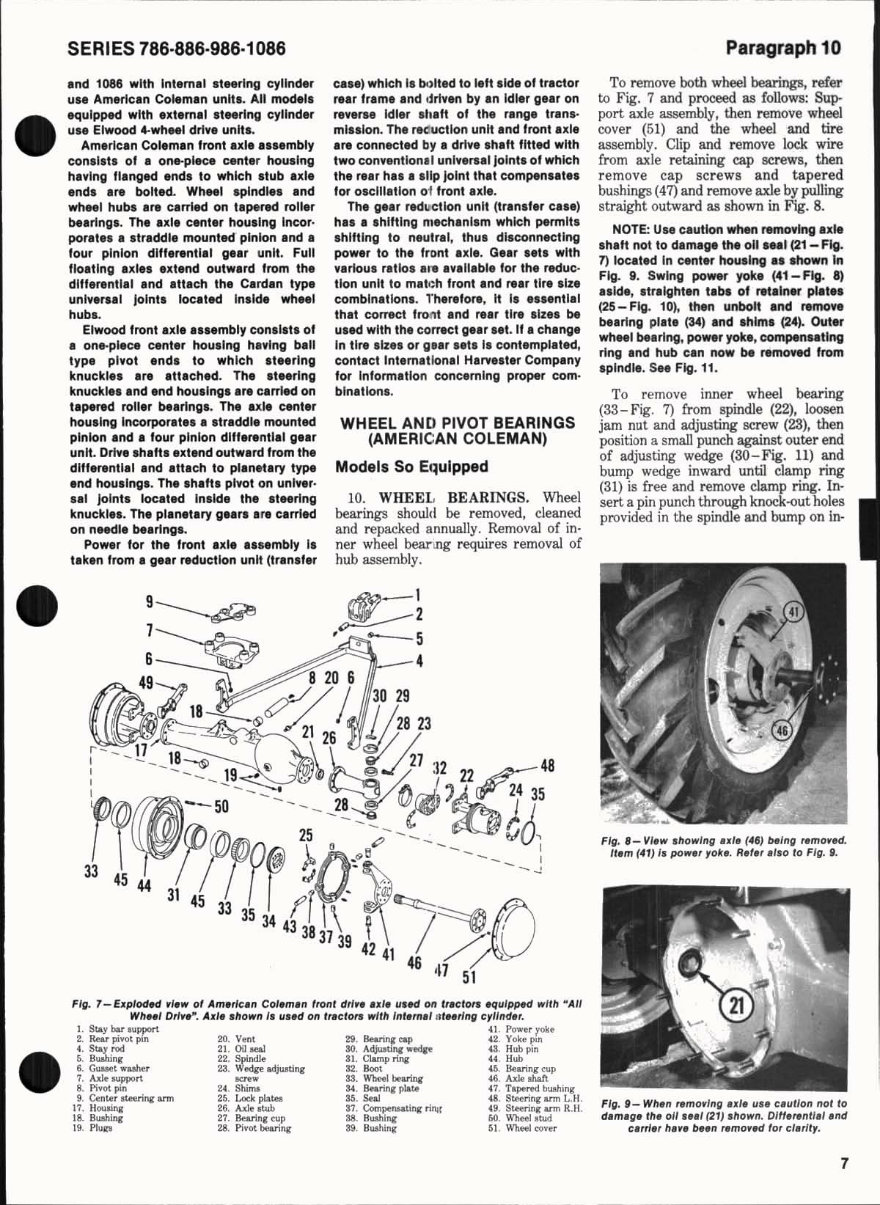
SERIES 786·886·986·1086 and 1088 with Intema' .t .. rlng cylinder u •• American Co .. man unit •. All model. equipped with extIma' ateerlng cylinder u •• Elwood 4-whM' drive unit •• Amerlcln Colaman lront axle •••• mbly conllata 01 • on.plKe canter !lousing having flanglld endl 10 which .tub ul. endl are bolted. Wh .. , splndl.. and wheel hub. are carrilld on tape'*' roller bearings. The axle cantar housing Incor- porat •• a atraddle mounted pinion and, four pinion differential g .. r unit. Full flo,tlng axl •• extend outward from the dilierentla' and attach the Cardan type UnIY8rU' Joint. located Inllde wh .. , hub• • Elwoocllront ule .... mbly conala" of • on.plece center housing having ball type pivot and. to which 't,.rlng knuckl.. are attlchad. The .teerlng knuckl •• and Ind houslnga are c.lrrIed on 'apenld rohr bIt,rlnga. The axle center housing Incorpor.t., •• tr.ddl. mounted pinion .nd • lour pinion dlff.r.ntl.1 g •• r unit. Drln .h.'t, .xtend outw.rd from the dlff.rentl.1 .nd .tt.ch to pl.n.t.ry type .nd hou'lng,. Th. ,h.ft, pl ... ot on unlver· •• 1 Joint. Ioc.ted Inlld. the Iteerlng knuckl.l. Th. plln.t.ry g •• rl Ira c.rrled on nMdla be.rlngl. Pow.r lor the front axl ..... mbly II t.kan from. g •• r reduction unit (tr.nlf.r c ... ) whk:h II bI)lted to left Iki. 01 tr.ctor re.r frame and drl'en by .n Idl.r g.ar on re,.ra. Idl.r ' haft of the rang. tr.na· ml'llon. Th. recructlon unit .nd front axl. .r. connected by' drl .... ,h.ft fitted with two conventional unlver .. 1 Joint. of whk:h the rur h ... Illp joint th.t compenaat •• for olcillation 01 front axl •. Th. g.ar red u:ctl on unit (tr.n.f.r c .. e) h ... Ihlttlng mech,nl'm whk:h permit. • hlltlng to nautrel, thus disconnecting power to the front axl •. G.er •• t. with .... rIou. retlo ..... a"lI.bl. lor the reduc· tlon unit to mat.:h front and r.ar tire .Ize comblnatlonl. rher.for., It I, .... nt,., that COlTact front .nd re.r tire .Ize. be u. ed with the coract g •• r •• t. If • ch.nge In tire , iz .. or g •• r .. t. I. contempl.ted, cont.ct Int.matlon.' H.rv .. ter Company lor Inform.tlon conc.rnlng proper com· blnatlon ,. WHEEL AND PIVOT BEARINGS (AMERICAN COLEMAN) Model. So Equipped 10. WHEEL BEARINGS. Wheel bearings should be removed, cleaned and repacked annually. Removal of in · ner wh eel bearmg requires removal of hub assembly. .t== ~ • - 5 4 Fig. 7-EJfplod.c1 ,I.w of Am.rlc.n Col.m. n fronl drl, • • d. 1I' .c1 on Irlc lora ~ulppld willi ~ AII WII .. I DrI .. ~. Ad •• hown I, 1I.1td on Ir.clon wllh I ",.t".' nl .. rlng "II/tIJ., . l. Stfoy bar oul'pOrt 41. Power r olle 2. Rear piVO! pin 20. Veftt 29. BMrina:.... ' 2. Yok .. ~1fI ,. S~ rod 21. Oil oeal SO. A<\;.Imnc w«Ip 43. Hub PI" 6. B...bl", 22. Sp(nd)e 31. Clamp I'iJ\i U . lIub 6. Gullet ......... 23. Wedjre a<\iusd"i' 32. 8001 ' 6. lIearing cup 7. A1k oupport ..".,.. 33. WbeeI bearinc 411. Axle oIW't 8. Pi .M pm 24 . Stun. U. BMrinIJ plIo~ (7. T"",""",, buahing 9. Cente. _ri", arm 26. Locl< p1a1el 15 . SnI 48. Steering arm L.H. 17. HOUJIna: 26. A.de rIub 87. Compensatlllg nlll! 49. Steen.., arm R. II . 18. Blllhinr 27. BNrina: eup 38. B IIIhIna: 60. WbeeI I U>d 19. PluJII 28. Pivot bearing 39. Blllhinr 51. Wheel cover Paragraph 10 To remove both wheel bearings, refer to Fig. 7 and proceed as follows: Sup- port axle assembly, then remove wheel cove r (5 1) and the wheel and tire assembly. Clip and remove lock wire from axle retaining cap screws, then remove cap screws a nd tapered bus hings (47) and remove ax1e by pulling straight outward as shown in Fig. 8. NOTE: U .. c.utlon when removing .xl • . h.ft not to d.mag. the 011 ... , (21- Flg. 7) located In canter hauling .. shown In Fig. g. Swing power yoka (41- Flg. a) .. Ide , .tr.lght.n t.b. of ret.lner pl.t •• (25 - Fig. 10), than unbolt end remo .. beerlng pl.te (34) and Ihlml (24). Out.r wheel bearing. power yok. , compenl.tlng ring end hub cen now be remoftd from 'plndl• . Se. Fig. 11. To remove inner wheel bearing (33- Fig. 7) from spindle (22), loosen jam nut and adjusting screw (23), then position a small punch against outer e nd of adjus ti ng wedge (SO - Fig. 11) and bump wedge inward until clamp ring (31) is free and remove clamp ring. In· s ert a pin punch through knock-out holes provi ded in the spindle and bump on in· Fig. 1_ VI.w . howlng ul. ( .,, "'ng flmo ,ltd . ".m (.,) I, pow• • ,ok •. R.f •• " '0 10 Fig. J. FIg. J- Wh.n flm o,/ng ul. II" c. ll llon nol to d.m.g. fh. 011 ... 1 (21) , lIown. Om.,.nf l .l.nd ,.,rI.r h.,. "-n r.mo, .c1 for cl.rlf,. 7
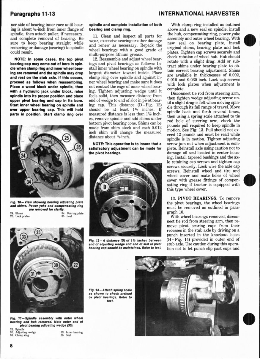
Paragraphs 11·13 ner s ide of bearing inner race until bear- ing is about 'It-inch from inner nange of spindl e, then attach puller, if necessary, and comp lete removal of bearing. Be sure to keep bearing straight while removing or damage (sooring) to spindle couki result. NOTE: In some c ..... the lop plyot belrlng CIP mlY com. out of bore In . pln. die when cllmp rlng and 1"lMr whHl bt., · Ing are removed and the .plndle ml, drop and .... t on the ,Iub ul •. II thl' occurs, Pf'OCMd •• lollow. when re .... mbllng. Place. wood block und .... plndle, tMn wtth • hydraulic Jack und.r block, r,I •• .plndle Into It. proper po.ltlon .nd pile. upper plntl blaring and CIP In It. bore. Start InMr whMl b .. rlng on .plndle . nd ov.r upper bearing cap. Thl, will hold part. In po.ltlon. Start clamp ring over Fit . 10- View .lIow'"'1 bHrl ,." ,djll.,/1Ig pI.f, .nd .II/mL Po_r rob ,,,d c:om~lI .. tl n" rlnfl 'f' ,.mo~H for til"'" 24. ShIma a. . BMrinr pIo.tII U. Loclt ~ U. Seal Fi ll. 11 - Splndl ..... mbly It'JlIt Olll.r wh .. 1 /H.rlng . nd hllb ,.moJIld. Nor. olll.r ."d 01 plJor /H.rI"g 'dllI.U"g wHg. (~). "'- SO. A~ '""'" U. In .... beNi ..... 31. Clamp rirqr H. Seal 8 INTERNATIONAL HARVESTER spindle and complete Installallon of both bearing and clamp ring. II. Clean and inspect all parts for wear, excessive scoring or other damage and renew as necessary. Repack the wheel bearings with a good grade of multi·purpose lithium grease. 12. Reassemble and adjust wht..oel bear· ings and pivot bearings as follows: In· stall inner wheel bearing on spindle with largest diameter toward inside. Place clamp ring over spindle and against in· ner wheel bearing and make sure it does not contact the cage of inner wheel bear· ing. Tighten adjusting wedge until it feels solid, then measure distance from end of wedge to end of slot in pi~-ot bear· ing cap. This distance (D-f'ig. 12) should be at least I lfa inches. If measured distance is less than 1*11 inch· es, remove spindle and add shims under bottom pivot bearing cone. Shims can be made from shim stock and each 0.012 inch shim will change the measured distance about IIt·inch. NOTE: This operation Is to Inlure thlt a .. tl l lactOfY adJultment can be made IOf the pivot bearlngl. Fig. fZ-A dl.l.nc. (DJ of 1 '111 Inell." /Hlw .. " .rId ol.dJII.II"g wlldg • • "d ."d 01 .101 lit plrot ",.rlltg up . 1I01l1d /H m.I"t.I ,,", R .f" 10 InL FIg. 1.t-Att.cl! . pring .c.l. II .1I0w" to ch.d: p,.lo.d OJ plrol but lng .. R.I " 10 t • • L With clamp ring installed as outlined above and a new seal on spindle, install the hub, compensati ng ring, power yoke assembly. and outer wheel bearing. With new seal on bearing plate, install original shims, bearing plate and lock plates. Tighten cap screws securely and check rotation of wheel hub. Hub should rotate with a slight drag. Add or sub- tract shims under bearing plate to ob- tain correct bearing adjustment. Shims are available in thicknesses of 0.002, 0.010 and 0.030 inch. Lock cap screws with lock plates when adjustment is complete. Disconnect tie rod from steering arm, then tighten wedge adjusting screw un· til a slight drag is felt when moving spin· die through its full range of travel. Move spindle back and forth several times, then using a spring scale attached to tie rod . hole or steering arm, check the pounds pull required to keep spindle in motion. See Fig. 13. Pull should not ex· ceed 12 pounds and must be read while spindle is in motion. Tighten adjusting screw jam nut when adjustment is com· plete. Reinstall axle using caution not to damage oil seal located in center hous- ing. Install tapered bushings and the ax· Ie retaining cap screws and tighten cap screws securely. Lock wire the axle cap screws. Reinstall wheel and tire and wheel cover and mate holes of wheel cover with grease fittings of compen· sating ring if tractor is equipped with this type wheel cover. 13. PIVOT BEARINGS. To remove the pivot bearings, the wheel bearings must be removed as outlined in para. graph 10. With wheel bearings removed, discon· nect tie rod from steering arm, then re- move pivot bearing cups from their re(,.'~sses in the stub axle by driving on a punch inserted in the knockout holes (H - Fig. 1 4) provided in outer end of stub axle. Use caution during this opera· tion not to l et punch slip past cups and
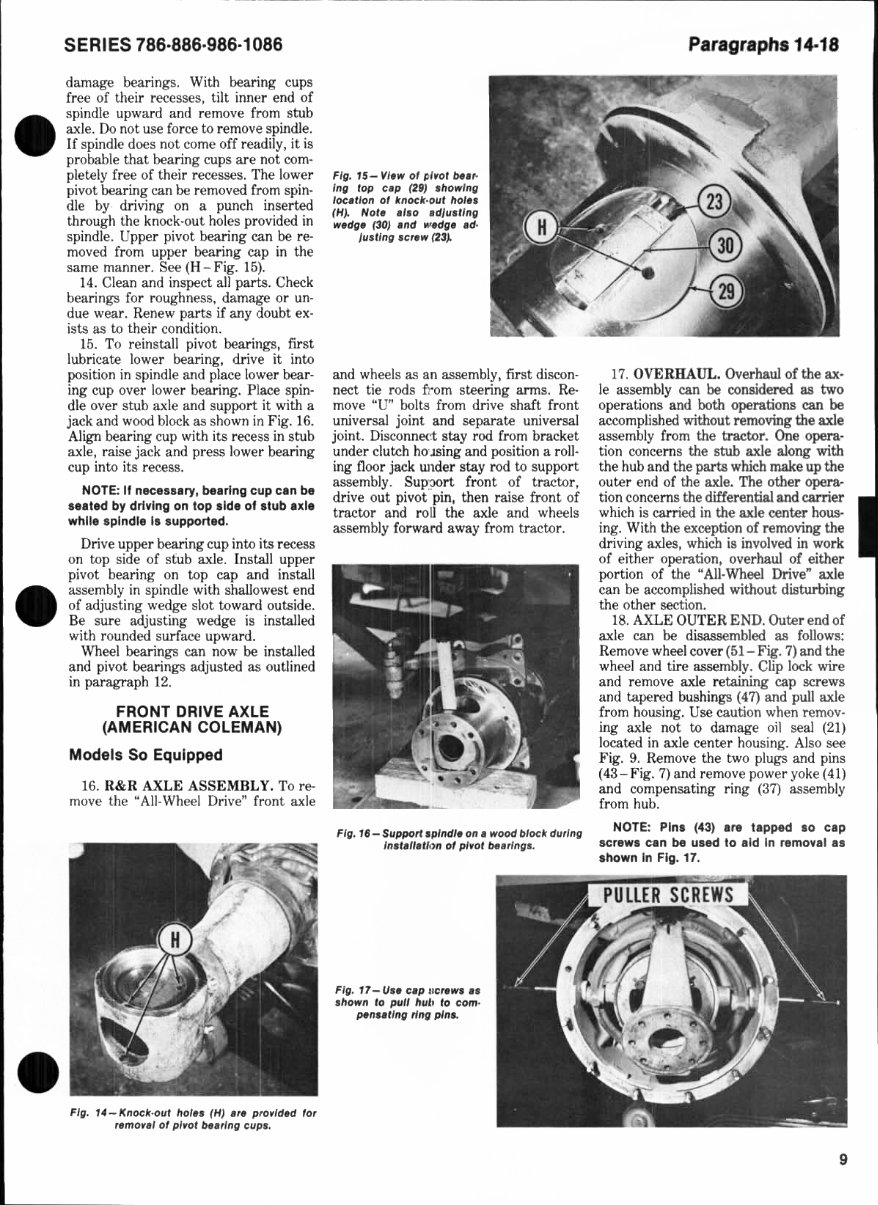
• SERIES 786·886·986·1086 damage bearings. With bearing cups free of their recesses, tilt inner end of spindle upward and remove from stub axle. Do not use force to remove spind l e. If spindle does not come off readily, it is probable that bearing cups are not com· pletely free of their recesses. The lower pivot bearing can be removed from spin· die by driving on a punch inserted through the knock-out holes provided in spindle. Upper pivot bearing can be re- moved from upper bearing cap in the same manner. See (H-Fig. 1 5). 14. Clean and inspect all parts. Check bearings fo r toughness, damage or un- due wear. Renew parts if any doubt ex- ists as to their condition. 1 5. To reinstall pivot hearings, first lubricate lower bearing, drive it into position in spindle and place lower bear- ing cup over lower bearing. Place spin- dle over stub axle and support it with a jack and wood block as shown in Fig. 16. Align bearing cup with its recess in stub axle, raise jack and press lower bearing cup into its reeess. NOTE: If neeesury, beerlng cup een be s •• ted by driving on top side of stub u l. while spindle Is supported. Drive upper bearing cup intD its recess on top side of s(ub axle. Install upper pivot bearing on top cap and install assembly in spindle with shallowest end of adjusting wedge slot toward outside. Be sure adjusting wedge is installed with rounded surface upward. Wheel bearings can now be installed and pivot bearings adjusted as out li ned in paragraph 12. FRONT DRIVE AXLE (AMERICAN COLEMAN) Models So Equipped 16. R&R AXLE ASSEJ\lBLY. To re- move the "All-Wheel Drive" front axle Fig. ,4-/(noeff·Ollt hoi •• ( HI .r. pro,'d.d lor remortl 01 plWl! bt,,' ng eup •• FIll. 15- VI .w 01 ~ I,ot bt.,. IIIg top e.p (29) . howlnll loe.flon 01 boek·ouf hoi .. (H}. NOf. .'so . dJu.tlIIg w.dQ' (30) .nd IoI'HIi' .tJ. Ju.'/ng .er.w (23}. and wheels as an assembly, first discon- n ect tie rods from steering arms. Re- move "U" bolts from drive shaft fro nt universal joint and separate universal joint. Disconnect. stay rod from bracket under dutch hO- lSing and position a roll · ing floor jack wlder stay rod tD support assembly. Sup:?Ort front of tractor, drive out pivot pin, then raise front of tractor and roU the axle and wheels assembly forward away from tractDr. Fig. '1- Support splnell. on. wood bloe/{ duri ng III.I.II.,/ "n 01 pl ,ol bt.rlllg •• Fig. T7 _U .. up IlertWl II ./lown 10 pull hul. 10 eom· pennl/ng ring pins. Paragraphs 14·18 17. OVERHAUL. Overhaul of the ax- le assembly can be considered as two operations and both operations can be accomplished without removing the axle assembly from the tractor. One opera- tion concerns the stub axle along with the hub and the parts which make up the outer end of the axle. The other opera- tion concerns the differential and carrier which is carried in the axle center hous- ing. With the exception of removing the driving axles, which is involved in work of either operation, overhaul of either portion of the "All-Wheel Drive" axle can be accomplished without disturbing the other section. 18. AXLE OUTER END. Outer end of axle can be disassembled as follows: Remove wheel cover (51- Fig. 7) and the wheel and tire assembly. Clip lock wire and remove axle retai ni ng cap screws and tapered bushings (47) and pull axle from housing. Use caution when remov- ing axle not to damage oil seal (21) located in axle center housing. Also see Fig. 9. Remove the two plugs and pins (43- F ig. 7) and remove power yoke (41) and compensating ring (37) assembly from hub. NOTE: Pins (43) .r. t.pped 10 CIP screws e.n be used to lid In remove I .. shown In Fig. 17. 9
This professional technical manual contains service, maintenance, and troubleshooting information for your IH International Harvester 986 tractor, covering all models, engines, trim, and transmission types. It is the same manual used in the local service/repair shop and is guaranteed to be fully functional without any missing or corrupt parts or pages.
Written by the manufacturers, this original workshop manual contains hundreds of pages of diagrams and detailed information for specific vehicle or equipment repair. It includes pictures and easy-to-follow directions on what tools are needed and how the repair is performed.
The manual covers the engine, lubrication system, cooling system, fuel system, disassembly and servicing, general, separation, clutch, transmission, drive chain & sprockets, rear axle, brakes, front axle, steering, shocks, body work, intake & exhaust, hydraulic system, electrical system, routine maintenance, advanced troubleshooting, and wiring diagram, plus a lot more info.
Having the manual in an electronic format is a huge advantage as it allows you to print the desired section from your PC and dispose of it once the repair or service is completed. Whether using a paper manual or electronic version, you'll find the same features in both. This manual includes step-by-step repair procedures, critical specifications, illustrations or pictures, maintenance, disassembly, assembly, cleaning and reinstalling procedures, and much more.
This workshop repair service manual contains detailed substeps that expand on repair procedure information, notes, cautions, and warnings throughout each chapter, numbered instructions, bold figure numbers, detailed illustrations, drawings, and photos, an enlarged inset to help you identify and examine parts in detail, and a numbered table of contents for easy navigation. It also makes it easy to diagnose and repair problems with your machine's electrical system, with troubleshooting and electrical service procedures combined with detailed wiring diagrams for ease of use.
File Format: .PDF
Language: English
Specifications: Full Printable
Zoom IN/OUT: Yes
Delivery: Instant
Requirements: Adobe Reader & Win
Compatible: All Versions of Windows & Mac
Recently Viewed
5,521,897Happy Clients
2,594,462eManuals
1,120,453Trusted Sellers
15Years in Business
Price:
Actual Price:
International Harvester 786/886/986/1086 Tractors OEM Service & Repair Manual