


SHOP MANUAL
INTERNATIONAL
HARVESTER
SERIES
3088·3288·3488 Hydro·3688
Engine serial number is stamped on right side of engine crankcase on Models 3088 and 3288. On Models
3488 Hydro and 3688, engine serial number is stamped on left side of engine crankcase. On a" models,
tractor serial number is stamped on name plate attached to right side of rear frame. Cab/ROPS serial and
model numbers are stamped on a plate attached on right side.
INDEX (BY STARTING PARAGRAPH)
BRAKES
Adjustment. ................... .
Bleeding ...................... .
Brake Control Valve ............ .
R&R and Overhaul. ............. .
CLUTCH, ENGINE
Adjustment. ................... .
Hydraulic Assist
Clutch Cylinder ............... .
Overhaul ..................... .
Remove and Reinstall ........... .
COOLING SYSTEM
Coolant Filter-Conditioner ........ .
Fan .......................... .
Radiator ...................... .
Water Pump ................... .
DIESEL FUEL SYSTEM
Adjustment. ................... .
Ether Starting Aid .............. .
Filters and Bleeding ............. .
Injection Nozzles ............... .
Injection Pump ................. .
Static Timing .................. .
ELECTRICAL SYSTEM
Alternator and Regulator ......... .
Starting Motor ................. .
Starter Solenoid ................ .
ENGINE
2
Assembly, R&R ................ .
Cam Followers ................. .
Camshaft and Bearings .......... .
Connecting Rods
and Bearings ................. .
Cooling Tubes,
Coolant Directors
and Nozzle Sleeves ............ .
Crankshaft and Main
Bearings .................... .
3088
179
178
182
181
112
11.9
118
117
106
103
102
104
94
100
89
96
90
92
107
110
111
45
52
68
76
47
78
3288
179
178
182
181
112
119
118
117
106
103
102
104
94
100
89
96
90
92
107
110
111
45
52
68
76
47
78
3488
Hydro
179
178
182
181
106
103
102
105
95
100
89
96
91
93
107
110
III
45
53
70
77
47
79
3688
179
178
182
181
112
119
118
117
106
103
102
105
95
100
89
96
91
93
107
110
111
45
53
70
77
47
79
3688
Hi·Clear
179
178
182
181
112
119
118
117
106
103
102
105
95
100
89
96
91
93
107
110
III
45
53
70
77
47
79
INDEX (CONT.)
3488 3688
3088 3288 Hydro 3688 Hi-Clear
ENGINE CONT.
Crankshaft Oil Seals .............. 80 80 80 80 80
Cylinder Head .................. 46 46 46 46 46
Flywheel ...................... 82 82 82 82 82
Oil Cooler ...................... 87 87 88 88 88
Oil Pressure Regulator ............ 85 85 86 86 86
OilPump ...................... 83 83 84 84 84
Piston and Rod Units ............. 72 72 72 72 72
Piston Pins ..................... 75 75 75 75 75
Pistons, Sleeves
and Rings .................... 73 73 74 74 74
Timing Gear Cover .............. 59 59 59 59 59
Timing Gears ................... 60 60 64 64 64
Valves, Guides
and Springs ................... 50 50 51 51 51
Valve Levers ................... 54 54 55 55 55
Valve Rotators .................. 56 56 56 56 56
Valve Timing ................... 57 57 58 58 58
Valves and Seats ................ 48 48 49 49 49
FINAL DRIVE
Bearing Adjustment ............ 175 175 175 175 177
R&R and Overhaul ............. 174 174 174 174 176
FRONT SYSTEM
All-Wheel Drive ................ 5 5 5 5
Axle Main Member ............. 1 1 1 1 2
Steering Knuckles .............. 4 4 4 4 4
Tie Rods and Toe-in ............. 3 3 3 3 3
HYDRAULIC SYSTEM
Auxiliary Control Valve ......... 218 218 218 218 218
Auxiliary Coupler .............. 219 219 219 219 219
Control Linkage
Adjustment ........... • ...... 196 196 196 196 196
Hydraulic Lift Housing .......... 205 205 205 205 205
Hydraulic Pump ................ 214 214 215 215 214
Hydraulic Seat ................. 221 221 221 221 221
Test and Adjust ................ 188 188 191 191 188
Troubleshooting ............... 186 186 187 187 186
HYDROSTATIC DRIVE
Adjustment ................... 141
Disassembly ................... 152
Lubrication and Filter ........... 140
Pressure Checks ............... 146
Reassemble and Reinstall ........ 162
Removal ...................... 151
System Clean-up ............... 166
Troubleshooting ............... 139
MAIN BEVEL GEAR
AND DIFFERENTIAL
Adjustment ................... 167 167 167 167 167
Differential Lock ............... 171 171 171 171 171
R&R Bevel Gears .............. 169 169 169 169 169
R&R Differential ............... 1(0 170 170 170 170
POWER STEERING SYSTEM
Filter, Lubrication and
Bleeding .................... 18 18 18 18 18
Flow Divider .................. 36 36 37 36 36
HandPump ................... 34 34 34 34 34
Multiple Control Valve .......... 39 39 40 39 39
Multi-Valve and Oil Cooler ....... 42
Oil Cooler ..................... 41 41 41 41
Operation ..................... 16 16 17 16 16
Operational Tests .............. 20 20 21 20 20
Pump ............. • .......... 29 29 32 29 29
Steering Cylinder .............. 38 38 38 38 38
3
INDEX (CONT.)
3488 3688
3088 3288 Hydro 3688 Hi-Clear
POWER STEERING CONT.
Telescoping Steering
Column ..................... 44 44 44 44 44
Tilt Steering Wheel ............. 43 43 43 43 43
Troubleshooting ............... 19 19 19 19 19
POWER TAKE-OFF
Control Cable Adjustment ....... 185 185 185 185 185
Pressure Check and
. Adjustment .................. 183 183 183 183 183
R&R and Overhaul ............. 184 184 184 184 184
RANGE TRANSMISSION
Linkage Adjustment ............ 137 137 137 137 137
Overhaul ...................... 126 126 126 126 126
Remove and Reinstall ........... 125 125 125 125 125
TORQUE AMPLIFIER AND
SPEED TRANSMISSION
Adjustment ................... 120 120 120 120
Overhaul ...................... 124 124 124 124
Remove and Reinstall ........... 123 123 123 123
Torque Amplifier
Shift Solenoid ................. 121 121 121 121
Transmission Brake ............ 122 122 122 122
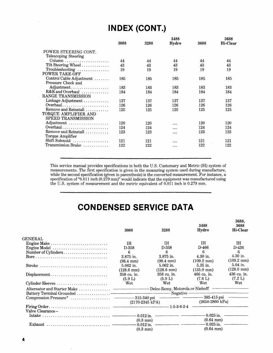
This service manual provides specifications in both the U.S. Customary and Metric (SI) system of
measurements. The first specification is given in the measuring system used during manufacture,
while the second specification (given in parenthesis) is the converted measurement. For instance, a
specification of "0.011 inch (0.279 mm)" would indicate that the equipment was manufactured using
the U.S. system of measurement and the metric equivalent of 0.011 inch is 0.279 mm.
CONDENSED SERVICE DATA
3488
3088 3288 Hydro
3688,
3688
Hi-Clear
GENERAL
Engine Make .......................... . IH IH IH IH
Engine Model ......................... . D-358 D-358 D-466 D-436
Number of Cylinders .................... .
Bore ................................. .
6 6 6 6
3.875 in. 3.875 in. 4.30 in.
4.30 in.
Stroke ............................... .
(98.4 mm) (98.4 mm) (109.2 mm)
(109.2 mm)
5.062 in. 5.062 in. 5.35 in.
5.04 in.
(128.6 mm) (128.6 mm) (135.9 mm)
(128.0 mm)
Displacement .......................... . 358 cu. in. 358 cu. in. 466 cu. in. 436 cu. in.
(5.9 L) (5.9 L) (7.6 L) (7.2 L)
Cylinder Sleeves ....................... . Wet Wet Wet Wet
Alternator and Starter Make . . . . . . . . . . . . . . . Delco-Remy, Motorola or Niehoff
Battery Terminal Grounded ................ -----------Negative -----------
CompressionPressure* ................... ----315-340 psi ----385-415 psi
(2170-2345 kPA) (2650-2860 kPa)
Firing Order ............................ . ----------1-5-3-6-2-4
Valve Clearance-
Intake ............................... . -----0.012 in. ----- -----0.025 in.
Exhaust ............................. .
(0.3 mm) (0.64 mm)
-----0.012 in. ----- -----0.025in. -----
(0.3 mm) (0.64 mm)
4
CONDENSED SERVICE DATA (CONT.)
GENERAL CaNT.
Valve Seat Angle (Degrees)-
Intake ............................... .
Exhaust.· ............................ .
Injection Pump Make .................... .
Injection Pump Timing .................. ..
Engine Low Idle Rpm .................... .
Engine High Idle Rpm, No Load ........... .
Engine Full Load Rpm ................... .
Rated power (Pto) ...................... ..
* Approximate, at sea level, at cranking speed.
SIZE-CLEARANCES
Crankshaft Main Journal Diameter ......... .
Crankpin Diameter ...................... .
Camshaft Journal Diameter ............... .
Piston Pin Diameter ..................... .
Valve Stem Diameter-
Intake ............................... .
Exhaust ............................. .
Main Bearing Diametral Clearance ......... .
Rod Bearing Diametral Clearance .......... .
Piston Skirt Diametral Clearance .......... .
Crankshaft End Play ..................... .
Camshaft Bearing Diametral Clearance ..... .
Camshaft End Play ...................... .
CAPACITIES
Cooling System ......................... .
Crankcase Oil ........................... .
Transmission and Differential ............. .
Front Differential Housing
. (All-Wheel Drive) ...................... .
Front Wheel Hubs
(All-Wheel Drive) ...................... .
Hi-Clear Rear Axle Housing ............... .
3088 3288
-----45
-----45
---Robert Bosch ---
---- See Para. 92
3488
Hydro
3688,
3688
Hi·Clear
------30--------
-----45
----U.T.D.S. -----
-----18°BTDC -----
-----------700 --------------------
---------------------2MO----------------------
---------------------2400------------
80H.P.
(59.7 kW)
90 H.P.
(67.1 kW)
----3.1484-3.1492 in. --
(79.970-79.990 mm)
--~- 2.5185-2.5193 in. --
(63.970-63.990 mm)
---- 2.2813-2.2825 in. --
(57.945-57.975 mm)
---1.4172-1.4173in. --
(35.997-35.999 mm)
---0.3919-0.3923 in.
(9.954-9.964 mm)
---0.3911-0.3915 in.
(9.934-9.944 mm)
---0.0028-0.0055 in.
(0.07-0.14 mm)
---0.0023-0.0048 in.
(0.06-0.12 mm)
--- 0.0039-0.0047 in.
(0.10-0.12 mm)
---0.006-0.009 in. ---
(0.15-0.23 mm)
--- 0.0010-0.0033 in.
(0.025-0.084 mm)
---- 0.004-0.018 in. ----
(0.10-0.46 mm)
----24qts.
(22.7 L)
-----12 qts.
(11.4 L)
----90qts.
(85.2 L)
112 H.P. 113 H.P.
(83.9 kW) (84.4 kW)
--- 3.3742-3.3755 in.---
(85.705-85.738 mm)
--- 2.9977-2.9990 in. ----
(76.142-76.175 mm)
----2.2814-2.2825 in. ---
(57.948-57.976 mm)
---1.6248-1.6250in. ---
(41.270-41.275 mm)
--- 0.3718-0.3725 in.
(9.444-9.462 mm)
---0.3718-0.3725 in. -----
(9.444-9.462 mm)
---0.0018-0.0051 in. -----
(0.046-0.130 mm)
--- 0.0018-0.0051 in. -----
(0.046-0.130 mm)
--- 0.0045-0.0065 in. ---
(0.114-0.165 mm)
--- 0.006-0.012 in. -----
(0.15-0.30 mm)
---0.002-0.0066 in. -----
(0.05-0.167 mm)
----0.005-0.013 in. ----
(0.13-0.33 mm)
30 qts. 27 qts.
(28.3 L) (25.6 L)
--'----14 qts.
(13.2 L)
114 qts. 90 qts.
(107.9 L) (85.2 L)
--------------llpts.
(5.2 L)
-------------2.5 pts. ------------
(1.1 L)
4.5 qts.
(4.25 L)
5
Paragraphs 1·4
INTERNATIONAL HARVESTER
FRONT SYSTEM AXLE TYPE
AXLE MAIN MEMBER
All Models Except 3688 Hi·Clear
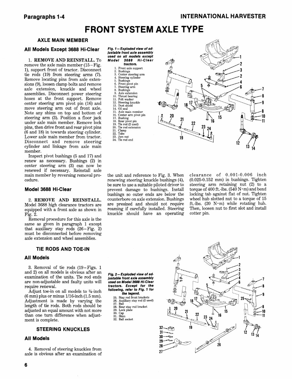
1. REMOVE AND REINSTALL. To
remove the axle main member (15-Fig.
1), support front of tractor. Disconnect
tie rods (19) from steering arms (7).
Remove locating pins from axle exten-
sions (9), loosen clamp bolts and remove
axle extension, knuckle and wheel
assemblies. Disconnect power steering
hoses at the front support. Remove
center steering arm pivot pin (16) and
move steering arm out of front axle.
Note any shims on top and bottom of
steering arm (3). Position a floor jack
under axle main member. Remove lock
pins, then drive front and rear pivot pins
(6 and 18) in towards steering cylinder.
Lower axle main member from tractor.
Disconnect and remove steering
cylinder and linkage from axle main
member.
Inspect pivot bushings (5 and 17) and
renew as necessary. Bushings (2) in
center steering arm (3) can now be
renewed if necessary. Reinstall axle
main member by reversing removal pro-
cedure.
Model 3688 Hi·Clear
2. REMOVE AND REINSTALL.
Model 3688 high clearance tractors are
equipped with a front axle as shown in
Fig. 2.
Removal procedure for this axle is the
same as given in paragraph 1 except
that auxiliary stay rods (26-Fig. 2)
must be disconnected before removing
axle extension and wheel assemblies.
TIE RODS AND TOE·IN
All Models
3. Removal of tie rods (19-Figs. 1
and 2) on all models is obvious after an
examination of the units. Tie rod ends
are non-adjustable and faulty units will
require renewal.
Adjust toe-in on all models to 1/4-inch
(6 mm) plus or minus 1I16-inch (1.5 mm).
Adjustment is made by varying the
length of tie rods. Both rods should be
adjusted an equal amount with not more
than one turn difference when adjust-
ment is complete.
STEERING KNUCKLES
All Models
4. Removal of steering knuckles from
axle is obvious after an examination of
6
Fig. 1- Exploded view of ad·
Justable front axle assembly
used on all models except
Model 3688 Hi·C/ear
tractors.
1. Front axle support
2. Bushings
3. Center steering arm
4. Steering cylinder
5. Bushings
6. Front pivot pin
7. Steering arm
8. Bushings
9. Axle extension
10. Thrust bearing
11. Felt washer
12. Steering knuckle
13. Dust shield
14. Oil seal
15. Axle main member
16. Center arm pivot pin
17. Bushing
18. Rear pivot pin
19. Tie rod (2 used)
20. Tie rod extension
21. Clamp
22. Tube
23. Jam nut
24. Tie rod end
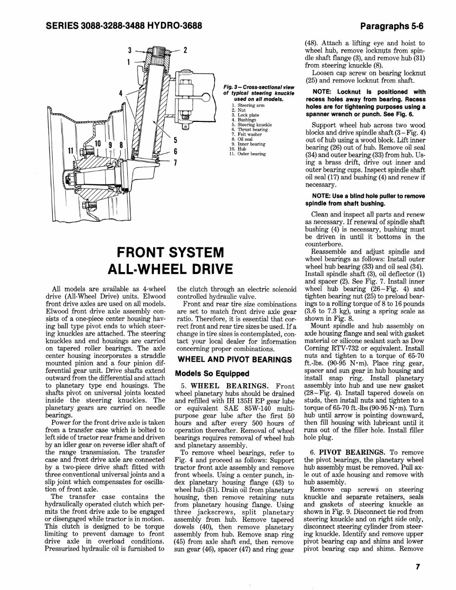
the unit and reference to Fig. 3. When
renewing steering knuckle bushings (4),
be sure to use a suitable piloted driver to
prevent damage to bushings. Install
bushings so outer ends are below the
counterbore on axle extension. Bushings
are presized and should not require
reaming if carefully installed. Steering
knuckle should have an operating
Fig. 2-Exploded view of ad·
Justable front axle assembly
used on Model 3688 HI·C/ear
tractors. Except for the
following, refer to Fig. 1 for
the legend.
25. Stay rod front brackets
26. Auxiliary stay rod (2 used)
27. Ball
28. Rear stay rod bracket
29. Lock plate
30. Cap
31. Shim
32. Ball socket
clearance of 0.001-0.006 inch
(0.025-0.152 mm) in bushings. Tighten
steering arm retaining nut (2) to a
torque of 400 ft. -lbs. (540 N' m) and bend
locking tab against flat of nut. Tighten
wheel hub slotted nut to a torque of 15
ft.-Ibs. (20 N· m) while rotating hub.
Then, loosen nut to first slot and install
cotter pin.
SERIES 3088·3288·3488 HYDRO·3688
Fig. 3 - Closs·sectlonal view
of typical steeling knuckle
used on all models.
1. Steering arm
2. Nut
3. Lock plate
4. Bushings
5. Steering knuckle
6. Thrust bearing
7. Felt washer
8. Oil seal
9. Inner bearing
10. Hub
11. Outer bearing
FRONT SYSTEM
ALL-WHEEL DRIVE
All models are available as 4-wheel
drive (All-Wheel Drive) units. Elwood
front drive axles are used on all models.
Elwood front drive axle assembly con-
sists of a one-piece center housing hav-
ing ball type pivot ends to which steer-
ing knuckles are attached. The. steering
knuckles and end housings are carried
on tapered roller bearings. The axle
center housing incorporates a straddle
mounted pinion and a four pinion dif-
ferential gear unit. Drive shafts extend
outward from the differential and attach
to planetary type end housings. The
shafts pivot on universal joints located
inside the steering knuckles. The
planetary gears are carried on needle
bearings.
Power for the front drive axle is taken
from a transfer case which is bolted to
left side of tractor rear frame and driven
by an idler gear on reverse idler shaft of
the range transmission. The transfer
case and front drive axle are connected
by a two-piece drive shaft fitted with
three conventional universal joints and a
slip joint which compensates for oscilla-
tion of front axle.
The transfer case contains the
hydraulically operated clutch which per-
mits the front drive axle to be engaged
or disengaged while tractor is in motion.
This clutch is designed to be torque
limiting to prevent damage to front
drive axle in overload conditions.
Pressurized hydraulic oil is furnished to
the clutch through an electric solenoid
controlled hydraulic valve.
Front and rear tire size combinations
are set to match front drive axle gear
ratio. Therefore, it is essential that cor-
rect front and rear tire sizes be used. If a
change in tire sizes is contemplated, con-
tact your local dealer for information
concerning proper combinations.
WHEEL AND PIVOT BEARINGS
Models So Equipped
5. WHEEL BEARINGS. Front
wheel planetary hubs should be drained
and refIlled with IH 135H EP gear lube
or equivalent SAE 85W-140 multi-
purpose gear lube after the first 50
hours and after every 500 hours of
operation thereafter. Removal of wheel
bearings requires removal of wheel hub
and planetary assembly.
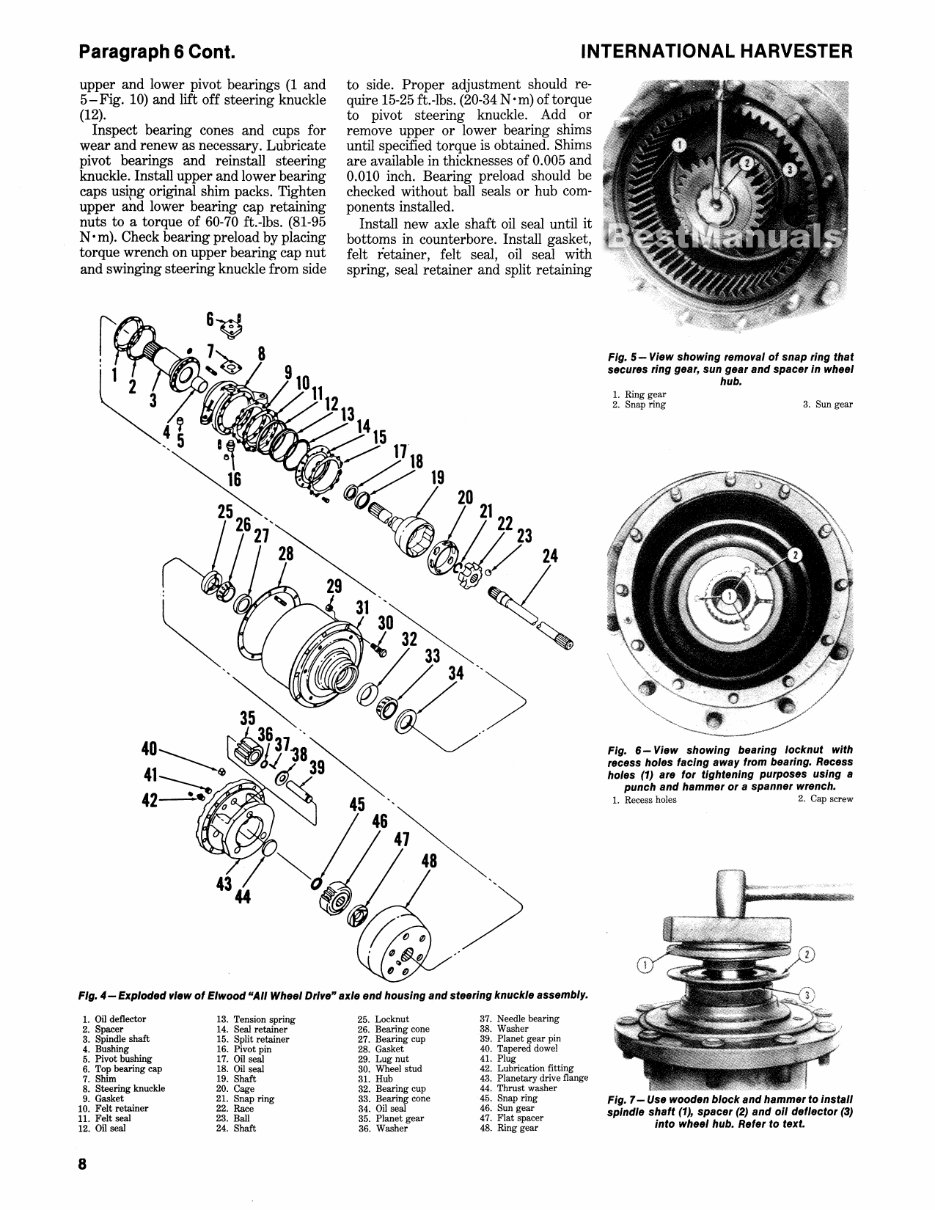
To remove wheel bearings, refer to
Fig. 4 and proceed as follows: Support
tractor front axle assembly and remove
front wheels. Using a center punch, in-
dex planetary housing flange (43) to
wheel hub (31). Drain oil from planetary
housing, then remove retaining nuts
from planetary housing flange. Using
three jackscrews, split planetary
assembly from hub. Remove tapered
dowels (40), then remove planetary
assembly from hub. Remove snap ring
(45) from axle shaft end, then remove
sun gear (46), spacer (47) and ring gear
Paragraphs 5·6
(48). Attach a lifting eye and hoist to
wheel hub, remove lockm.zts from spin-
dle shaft flange (3), and remove hub (31)
from steering knuckle (8).
Loosen cap screw on bearing locknut
(25) and remove locknut from shaft.
NOTE: Locknut Is pOSitioned with
recess holes away from bearing. Recess
holes are for tightening purposes using a
spanner wrench or punch. See Fig. 6.
Support wheel hub across two wood
blocks and drive spindle shaft (3 - Fig. 4)
out of hub using a wood block. Lift inner
bearing (26) out of hub. Remove oil seal
(34) and outer bearing (33) from hub. Us-
ing a brass drift, drive out inner and
outer bearing cups. Inspect spindle shaft
oil seal (17) and bushing (4) and renew if
necessary.
NOTE: Use a blind hole puller to remove
spindle from shaft bushing.
Clean and inspect all parts and renew
as necessary. If renewal of spindle shaft
bushing (4) is necessary, bushing must
be driven in until it bottoms in the
counterbore.
Reassemble and adjust spindle and
wheel bearings as follows: Install outer
wheel hub bearing (33) and oil seal (34).
Install spindle shaft (3), oil deflector (1)
and spacer (2). See Fig. 7. Install inner
wheel hub bearing (26-Fig. 4) and
tighten bearing nut (25) to preload bear-
ings to a rolling torque of 8 to 16 pounds
(3.6 to 7.3 kg), using a spring scale as
shown in Fig. 8.
Mount spindle and hub assembly on
axle housing flange and seal with gasket
material or silicone sealant such as Dow
Corning RTV-732 or equivalent. Install
nuts and tighten to a torque of 65-70
ft.-Ibs. (90-95 N ·m). Place ring gear,
spacer and sun gear in hub housing and
install snap ring. Install planetary
assembly into hub and use new gasket
(28-Fig. 4). Install tapered dowels on
studs, then install nuts and tighten to a
torque of 65-70 ft.-Ibs (90-95 N ·m). Turn
hub until arrow is pointing downward,
then fUl housing with lubricant until it
runs out of the fIller hole. Install fIller
hole plug.
6. PIVOT BEARINGS. To remove
the pivot bearings, the planetary wheel
hub asse~ly must be removed. Pull ax-
le out of axle housing and remove with
hub assembly.
Remove cap screwi on steering
knuckle and separate retainers, seals
and gaskets of steering knuckle as
shown in Fig. 9. Disconnect tie rod from
steering knuckle and on right side only,
disconnect steering cylinder from steer-
ing knuckle. Identify and remove upper
pivot bearing cap and shims and lower
pivot bearing cap and shims. Remove
7
Paragraph 6 Cont.
upper and lower pivot bearings (1 and
5-Fig. 10) and lift off steering knuckle
(12).
Inspect bearing cones and cups for
wear and renew as necessary. Lubricate
pivot bearings and reinstall steering
knuckle. Install upper and lower bearing
caps usipg original shim packs. Tighten
upper and lower bearing cap retaining
nuts to a torque of 60-70 ft.-lbs. (81-95
N· m). Check bearing preload by placing
torque wrench on upper bearing cap nut
and swinging steering knuckle from side
INTERNATIONAL HARVESTER
to side. Proper adjustment should re-
quire 15-25 ft.-lbs. (20-34 N • m) of torque
to pivot steering knuckle. Add or
remove upper or lower bearing shims
until specified torque is obtained. Shims
are available in thicknesses of 0.005 and
0.010 inch. Bearing preload should be
checked without ball seals or hub com-
ponents installed.
Install new axle shaft oil seal until it
bottoms in counterbore. Install gasket,
felt retainer, felt seal, oil seal with
spring, seal retainer and split retaining
Fig. 5 - View showing remo"al of snap ring that
secures ring gear, sun gear and spacer In wheel
hub.
1. Ring gear
2. Snap ring 3. Sun gear
Fig. 6 - View showing bearing locknut with
recess holes facing away from bearing. Recess
holes (1) are for tightening purposes using a
punch and hammer or a spanner wrench.
1. Recess holes 2. Cap screw
Fig. 4 - Exploded ,,'ew of Elwood "All Wheel DrI"e" axle end housing and steering knuckle assembly.
1. Oil deflector 13. Tension spring
2. Spacer 14. Seal retainer
3. Spindle shaft 15. Split retainer
4. Bushing
5. Pivot bushing
16. Pivot pin
17. Oil seal
6. Top bearing cap 18. Oil seal
7. Shim 19. Shaft
8. Steering knuckle 20. Cage
9. Gasket 21. Snap ring
10. Felt retainer 22. Race
11. Felt seal 23. Ball
12. Oil seal 24. Shaft
8
25. Locknut
26. Bearing cone
27. Bearing cup
28. Gasket
29. Lug nut
30. Wheel stud
31. Hub
32. Bearing cup
33. Bearing cone
34. Oil seal
35. Planet gear
36. Washer
37. Needle bearing
38. Washer
39. Planet gear pin
40. Tapered dowel
41. Plug
42. Lubrication fitting
43. Planetary drive flange
44. Thrust washer
45. Snap ring
46. Sun gear
47. FIat spacer
48. Ring gear
Fig. 7 - Use wooden block and hammer to install
spindle shaft (1), spacer (2) and 011 deflector (3)
into wheel hub. Refer to text.
SERIES 3088·3288·3488 HYDRO·3688
ring halves on rear of steering knuckle.
See Fig. 9. Install lockwashers and
mounting bolts and torque bolts to 10-15
ft.-lbs. (15-20 N ·m). Pack inside of ball
Fig. 8- View showing use of cord and spring
scale to measure bearing preload by means of
roiling torque. Refer to text
Fig. 9- View showing placement order of re·
talners, seals and gaskets used on steering
knuckle.
1. Outer split retainer
2. Seal retainer
3. Oil seal
1-&
2~
4. Felt seal
5. Felt retainer
6. Gasket
with good grade multi-purpose lithium
grease and install axle, spindle anQ. hub
assembly.
NOTE: When Installing axle shaft, be
careful not to damage axle shaft 011 seal.
When connecting tie rod to steering
knuckle, tighten slotted nut securely un-
til slot in nut aligns with hole in pin, then
install cotter pin.
Remainder of assembly is reverse· of
disassembly procedure.
FRONT DRIVE AXLE
Models So Equipped
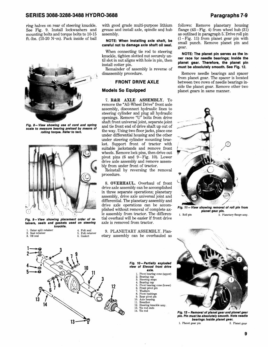
7. R&R AXLE ASSEMBLY. To
remove the "All-Wheel Drive" front axle
assembly, disconnect hydraulic lines to
steering cylinder and plug all hydraulic
openings. Remove "U" bolts from drive
shaft front universal joint, separate joint
and tie front end of drive shaft up out of
the way. Using two floor jacks, place one
under differential housing and the other
under steering cylinder mounting brac-
ket. Support front of tractor with
suitable jackstands and remove front
wheels. Remove lock pins, then drive out
pivot pins (6 and 9-Fig. 10). Lower
drive axle assembly and remove assem-
bly from under front of tractor.
Reinstall by reversing the removal
procedure.
8. OVERHAUL. Overhaul of front
drive axle assembly can be accomplished
in three separate operations; planetary
assembly, drive axle universal joint and
differential. The planetary assembly and
drive axle operations can be accom-
plished without removal of complete ax-
le assembly from tractor. The differen-
tial overhaul will be easier if front drive
axle is removed from tractor.
9. PLANETARY ASSEMBLY. Plan-
etary assembly can be overhauled as
Fig. 10- Partially exploded
view of Elwood front drive
axle.
1. Pivot bearing cone (upper)
3
I 12
~
2. Bearing cup
3. Steering stops
4. Bearing cup
5. Pivot bearing cone (lower)
6. Front pivot pin
7. Washers
8. Pivot bushings
9. Rear pivot pin
10. Axle housing
11. Breather
12. Steering knuckle assy.
13. Tie rod ends
14. Tie rod
Paragraphs 7·9
follows: Remove planetary housing
flange (43-Fig. 4) from wheel hub (31)
as outlined in paragraph 5: Drive roll pin
(I-Fig. 11) from planet gear pin with
small punch. Remove planet pin and
gear.
NOTE: The planet pin serves as the In·
ner race for needle bearings; Inside the
planet gear. Therefore, the planet pin
must be absolutely smooth. See Fig. 12.
Remove needle bearings and spacer
from planet gear. The spacer is located
between two rows of needle bearings in-
side the planet gear. Remove other two
planet gears in same manner.
Fig. 11- View showing removal of roll pin from
planet gear pin.
1. Roll pin 2. Planetary flange assy.
Fig. 12 - Removal of planet gear and planet gear
pin. Pin must be absolutely smooth. Note needle
bearings Inside planet gear.
1. Planet gear pin 2. Planet gear
9
Paragraphs 10·11
Clean and inspect all parts and renew
any showing excessive wear or other
damage. Assembly is the reverse of
disassembly. Tighten planetary housing
flange retaining nuts to a torque of
65-70 ft.~lbs. (90-95 Nom).
10. DRIVE AXLE SHAFT AND "U"
JOINT. Overhaul of axle drive shaft and
universal joint is as follows: Remove
planetary assembly, wheel hub and shaft
spindle as outlined in paragraph 5. Pull
axle shaft assembly from front drive
axle housing. Place inner axle in a soft
jawed vise. Hold outer shaft end and
strike backside of joint housing with it
soft faced hammer as shown in Fig. 13.
Remove lock ring from shaft and
discard. Use new lock ring when
reassembling. See Fig. 14. Tilt inner
race as shown in Fig. 15 until one ball
bearing can be removed. Repeat this
procedure removing all ball bearings.
Rotate universal joint cage 180 degrees
to the outer race bell. Roll cage until the
two elongated slots in cage align with
Fig. 13- Tap back face of universal Joint on axle
shaft (1) to gain access to letalnlng ling.
Fig. 14- View of dll"e axle universal Joint show·
Ing retaining ling (1). Renew ling upon
leassembly. Refer to text
10
INTERNATIONAL HARVESTER
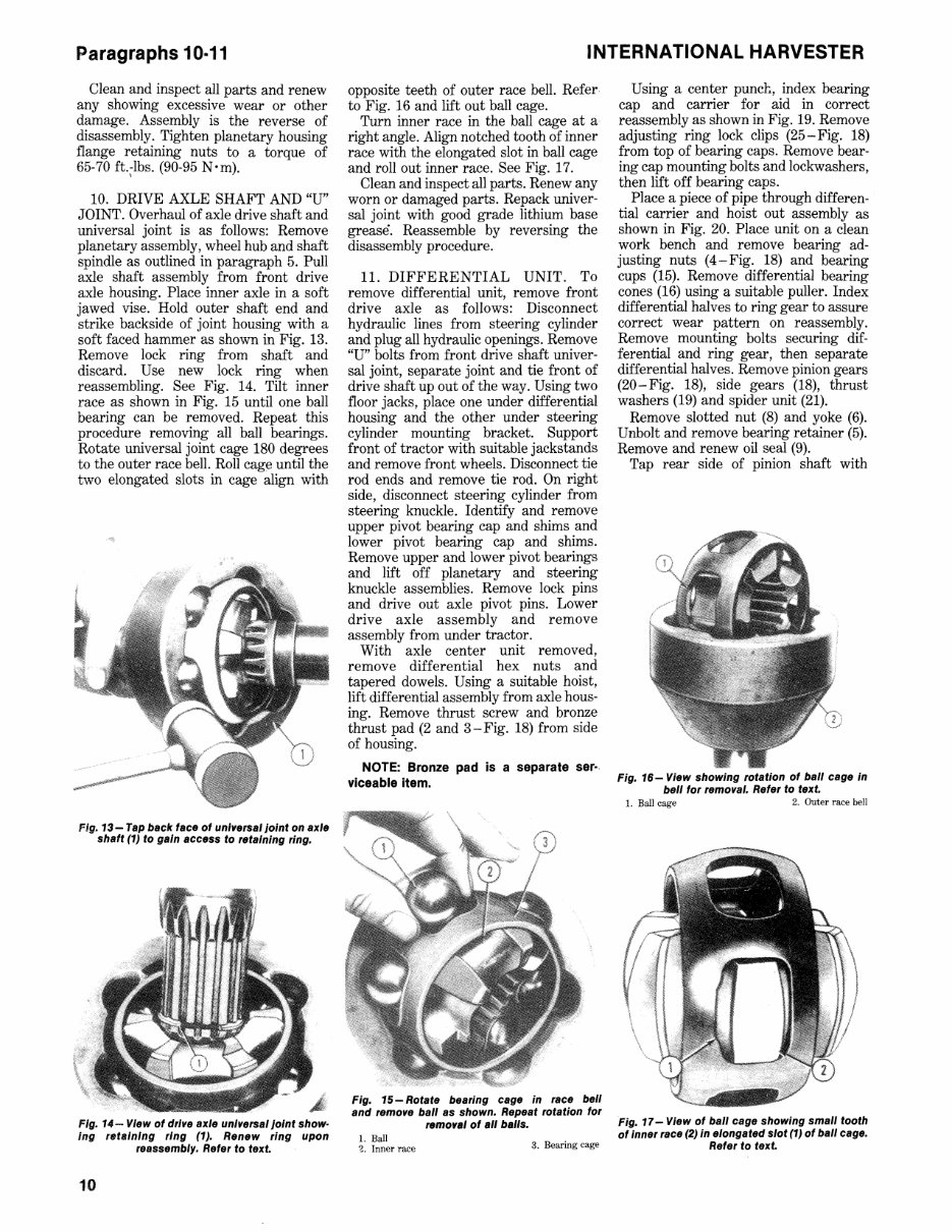
opposite teeth of outer race bell. Refer·
to Fig. 16 and lift out ball cage.
Turn inner race in the ball cage at a
right angle. Align notched tooth of inner
race with the elongated slot in ball cage
and roll out inner race. See Fig. 17.
Clean and inspect all parts. Renew any
worn or damaged parts. Repack univer-
sal joint with good grade lithium base
grease'. Reassemble by reversing the
disassembly procedure.
11. DIFFERENTIAL UNIT. To
remove differential unit, remove front
drive axle as follows: Disconnect
hydraulic lines from steering cylinder
and plug all hydraulic openings. Remove
"U" bolts from front drive shaft univer-
sal joint, separate joint and tie front of
drive shaft up out of the way. Using two
floor jacks, place one under differential
housing and the other under steering
cylinder mounting bracket. Support
front of tractor with suitable jackstands
and remove front wheels. Disconnect tie
rod ends and remove tie rod. On right
side, disconnect steering cylinder from
steering knuckle. Identify and remove
upper pivot bearing cap and shims and
lower pivot bearing cap and shims.
Remove upper and lower pivot bearings
and lift off planetary and steering
knuckle assemblies. Remove lock pins
and drive out axle pivot pins. Lower
drive axle assembly and remove
assembly from under tractor.
With axle center unit removed,
remove differential hex nuts and
tapered dowels. Using a suitable hoist,
lift differential assembly from axle hous-
ing. Remove thrust screw and bronze
thrust pad (2 and 3 - Fig. 18) from side
of housing.
NOTE: Bronze pad is a separate ser-
viceable item.
Fig. 15 - Rotate bealing cage in lace bell
and remove ball as shown. Repeat rotation fOl
removal of all balls.
1. Ball
3. Bearing cage
2. Inner race
Using a center punch, index bearing
cap and carrier for aid in correct
reassembly as shown in Fig. 19. Remove
adjusting ring lock clips (25-Fig. 18)
from top of bearing caps. Remove bear-
ing cap mounting bolts and lockwashers,
then lift off bearing caps.
Place a piece of pipe through differen-
tial carrier and hoist out assembly as
shown in Fig. 20. Place unit on a clean
work bench and remove bearing ad-
justing nuts (4-Fig. 18) and bearing
cups (15). Remove differential bearing
cones (16) using a suitable puller. Index
differential halves to ring gear to assure
correct wear pattern on reassembly.
Remove mounting bolts securing dif-
ferential and ring gear, then separate
differential halves. Remove pinion gears
(20-Fig. 18), side gears (18), thrust
washers (19) and spider unit (21).
Remove slotted nut (8) and yoke (6).
Unbolt and remove bearing retainer (5).
Remove and renew oil seal (9).
Tap rear side of pinion shaft with
Fig. 16- View showing rotation of ball cage In
bell fOl removal. Refel to text.
1. Ball cage 2. Outer race bell
Fig. 17- View of ball cage showing small tooth
of innel lace (2) In elongated slot (1) of ball cage.
Refel to text.
You're Reading a Preview
What's Included?
Fast Download Speeds
Online & Offline Access
Access PDF Contents & Bookmarks
Full Search Facility
Print one or all pages of your manual
$52.99
$68.99
IH 3088 3288 3488 Hydro 3688 Shop Manual
Viewed 92 Times Today

What's Included?
Fast Download Speeds
Online & Offline Access
Access PDF Contents & Bookmarks
Full Search Facility
Print one or all pages of your manual
$52.99
$68.99

Secure transaction
What's Included?
Fast Download Speeds
Online & Offline Access
Access PDF Contents & Bookmarks
Full Search Facility
Print one or all pages of your manual
Description
This service manual is an essential resource for DIY repair enthusiasts, from first-time owners to experienced technicians. It is designed in an easy-to-read format and provides comprehensive instructions necessary for accurate procedure execution. Keeping this manual accessible and referring to it regularly ensures that routine and preventive maintenance is performed efficiently, saving both time and cost by preventing premature failure and unnecessary repairs.
- BRAKES
- CLUTCH, ENGINE
- COOLING SYSTEM
- DIESEL FUEL SYSTEM
- ELECTRICAL SYSTEM
- ENGINE
- FINAL DRIVE
- FRONT SYSTEM
- HYDRAULIC SYSTEM
- HYDROSTATIC DRIVE
- MAIN BEVEL GEAR
- POWER STEERING SYSTEM
- POWER TAKE-OFF
- RANGE TRANSMISSION
- TORQUE
- SERVICE DATA
Language: English


