SHOP MANUAL INTERNATIONAL HARVESTER SERIES 100-130-140-200-230-240-404-2404 Series 100, 130 and 140 are available with either an adiustable or a non-adiustable front axle. Series 100, 130 and 140 Hi-Clearance are available with an adiustable type front axle only. Series 200, 230, 240 and 404 Farmall are available with single or dual wheel tricycle front system as well as an adiustable type front axle. The 240 International is avaUable only with an adlustable front axle. The 404 and 2404 Inter- national is available with an adiustable type front axle as well as a heavy duty fixed tread type front axle. Engine serial number is stamped on right side of crankcase and the serial number prefix is C-123 for all models except the 404 and 2404 which is C-135. Tractor serial number is stamped on a plate and on series 100, 130 and 140, the plate 15 attached on left side of clutch housing. On series 200, 230, 240, 404 and 2404, plate is aHached on right side of clutch housing. Suffix leHers of the serial number indicate the following: A-Distillate burning aHachment T -CoHon picker mounting attachment B-Kerosene burning aHachment U-High altitude aHochment C-L. P. Gas burning aHachment (Engine) V-Exhaust valve rotator aHachment 0-5000 ft. high altitude aHachment W-Forward and reverse drive aHachment E-8000 ft. high altitude aHachment X-High speed low and reverse aHachment J-Rockford clutch DO-High speed 3rd gear aHachment Serle. 100 130 140 I N D EX (By Starting Paragraph) Serle. 200 230 240 Series 404 2404 Serles 100 130 140 Series 200 230 240 BELT PULLEy .... . .. ..... .... 113 113 111 46 114 III 46 FINAL DRIVE BRAKES .................. .. 109 CARBURETOR . . . . . . . . . . . . . .. 46 CLUTCH Adjust ... ....... .... ...... 76 Clutch Shaft .. . . . 82 Overhaul . .. .............. 79 Release Bearing .... . . . . . . . 80 Remove and Reinstall. .. ... 77 COOLING SYSTEM Fan . ..................... 60 Radiator ... ... .. .... . .. . .. 58 ~ater Pump ... ........... 61 . 62 DIFFERENTIAL . . .. .... ... ... 102 ENGINE Cam Followers .. , . . . . . . . .. 29 Camshaft . ................ 35 Connecting Rods & Bearings 41 Crankshaft ... . . . . . . . . . . . .. 42 Cylinder Head .... . ....... 26 Engine Removal . . . . . . . . . .. 25 Flywheel ...... ....... .. .. 44 Ignition Timing ........ ... . 65 Main Bearings ......... ... 42 OU Pump ................. 45 Pistons and Rings . . . . . . . . .. 37 Piston Pins .. •.. ..... ..... • 40 Piston Removal ... ....... . 36 Rear 011 Seal. . . . . . . . . . . . .. 43 Rocker Arms .............. 30 Timing Gear Cover ..... . . " 33 Timing Gears . ............ 34 Valves and Seats .... ..... 27 Valve Guides and Springs .. 28 Valve Timing . . ........ . .. 32 76 82. 83 79 80 77 60 58 62 103 29 35 41 42 26 25 44 65 42 45 37 40 36 43 30 33 34 27 28 32 2 Printed In U.S.A. 76 84 79 BO 77 58 63 103 29 35 41 42 26 25 44 65 42 45 37 40 36 43 30 33 34 27 28 32 Axle Shafts . . . . . . . .. . . . . .. 105 Bull Gears . . . . . . . . . .. . . . .. 105 Bull Pinions ... ............ 104 FRONT SYSTEM Axle Main Membear . . . . . . .. 3 Steering Knuckles . . ...... .. 5 Tie Rods and Drag Link . . . .. 4 Tricycle Type .. .. .... . . . . . GOVERNOR ............. ... 56 HYDRAULIC SYSTEM Adjustment ... ............ 121 Cylinder and Valves Unit. .. 124 Lubrication and Bleeding ... 119 Operating Pressure ....... 120 Pump .. ... ... ..... ... . ... 122 Regulator and Safety Valve. Testing ... .. .... .......... 120 Trouble Shooting .. . ....... 120 PO~ER STEERING Lubrication a nd Bleeding ... . Operating Pressure ....... . Power Unit. .. ........ .... .. ... Pump .... . ... . .......... . Rotary Valve . ............ . PO~ER TAKE-OFF .......... 113 REAR AXLE .... ..... . ...... 105 STEERING GEAR Remove and Reinstall ...... 6 Overhaul.. ............... 7 TRANSMISSION Countershaft . ......... . ... 88 Reverse Idler . ... ......... 89 Shifter Rails and Forks . . . .. 86 Spline Shaft .. ......... ... 87 108 107 lOS 3 5 4 1 56 121. 132 124, 130 119. 126 120, 127 122, 129 131 120, 127 120, 128 12 13 16 19 113 108 8, 10 9,11 96 97 94 95 Serle. 404 2404 108 107 106 3 5 4 1 56 143 140 142A 148A 142 12 14 16 19 18 117 108 8, 10 9, 11 96 97 94 95
CONDENSED SERVICE DATA Sed .. Series Serl .. Serles Serl .. Series Serl .. Serl •• 100 200 140 404 100 200 140 404 GENERAL 130 230 240 2404 TUNE·UP (Continued) 130 230 240 2404 Engine Make .......... 0\1'11 Own Own Own Electrode Gap Engine ModeL ......... C -123 C-123 C-123 C-135 (LP·Gas.) ................... . 0.015 Number Cylinders ..... .4 4 4 4 Carburetor Make ....... - Carter, Zenith or Marvel-Schebler - Bore-Inches .......... . 3~ 31ri1 31ri1 314 float Setting. Carter .. . 17/ 64 17/ 64 17/ 64 Stroke-Inches .. .... ... 4 4 4 4n float Setting. Zenith . .. liz Ih Ih Displacement-Cu.·In .... 12~:.7 122.7 122.7 135 float Setting. M.s ... ..... . 14 Compression Ratio (Std.) 6.5 : 1 6.5:1 6.8 :1 7.4 :1 Engine Slow Idle-rpm. 425 425 425 425 Pistons Removed From .. Ab<)ve Above Above Above Engine High Idle-rpm. 1575 200,1815 140,1575 2300 Main Brgs .. Number of ... 3 3 3 3 230,1980 240.2200 Main and Rod Brgs. Adjustable . .... ........ No No No No SIZES-CAPACITIES-CLEARANCES Cylinder Sleeves . ...... Wet Wet Wet Wet Forward Speeds (Clearances in thousandths) (Standard) ........... .4 4 4 4 Crankshaft Journal Generator & Starter Diameter .. . .......... 2.1245 2.1245 2.1245 2.1245 I Make ................ D-R D-R D-R D-R Crankpin Diameter . .... 1.7495 1.7495 1.7495 1.7495 Camshaft Journal TUNE·UP Diameter Front (No.1) ......... 1.8115 1.8115 1.8115 1.8115 Firing Order ... ........ 1-3-4-2 1-3-4-2 1-3 -4-2 1-3-4-2 Intermediate (No.2) .. 1.5775 1.5775 1.5775 1.5775 Valve Tappet Gap. Rear (No.3) ..... .... 1.4995 1.4995 1.4995 1.4995 Intake ... . ........... 0.014H 0.014H O .014H 0.014H Piston Pin Diameter ... .,0.9 1935 0.91935 0.91935 0.8592 Valve Tappet Gap. Valve Stem Diameter ... 0.341 0.341 0.341 0.341 Exhaust. ......... •... 0.014H O.014H O.014H 0.020H Main Bearings Valve Seat Angle ...... 45 45 45 45 Running Clearance . ... 9-3 .9 .9-3.9 .9·3.9 .9· 3.9 Val ve Seat Width- Rod Bearings Inches ..... . ..... . ... 1riI IriI IriI 5/64 Running Clearance .. , ,9·3.4 .9 -3.4 .9-3.4 .9-3 .9 Ignition Distributor Rod Side Play . .. ...... 5-14 5-14 5-14 5-14 Make ................ 0WIl Own Own Own Piston Skirt Clearance . . . 1.1-1.9 1.1-1.9 1.1-1.9 1.1-1.9 Ignition Distributor Crankshaft End Play ... 4 -1 0 4-10 4-10 4-10 Symbol ... . ... . .. .. .. J or X JorX XorAB ABor Camshaft Bearing AH Clearance .. ......... ..9-5.4 .9 -5.4 .9-5.4 .9-5 .4 Ignition Magneto Camshaft End Play ...... 3·12 3-12 . 3-12 3-12 Make ..... . ...... '" .0Wl Own Own Cooling System-Gals .. 3* 3* 3* 3* Ignition Magneto Crankcase Oil-Qts. . .. 5 5 5 5 ModeL .. .. .. .. ...... H- 4 H-4 H-4 Transmission & Distributor Breaker Differential-Qts ...... 4 19 4 (6) 28 Gap ................. 0.020 0.020 0.020 0.020 Final Drive. Each- Magneto Breaker Gap .. 0.013 0.013 0.013 Quarts .. .. .. .... ..... Ph 11A! (7) Distributor T1IIling. Add for BP and/or Static ... ...... ... . ... TDC TDC TDC TDC PTO-Pints ............ 2 2 2 Distributor Timing. Touch Control (No Re- Full Advance ..... ... See Par. 67 mote Control.}-Pts .... 814 814 814 (7) Magneto Impulse Hydra·Touch- Pints . . ..... . .. 11 (8) Trip Point ... . .. . ... . TDC TDC TDC Magneto Lag Angle .... 35 0 35° 35 0 TIGHTENING TORQUES-Ft.·Lbs. Magneto Running Cylinder Head ......... See Par. 2&-- Timing . .. ... ....... .. 35 0 BTC 35° BTC 35 0 BTC Ignition Retard Mark & Timirlg Rod Nuts (Cotter Pins) . .40-45 40-45 40-45 flywheel .. ... ...... "DCl-4" "DCl-4" Rod Nuts (Self Lock) .... 43-49 43-49 43-49 Fem Belt Pulley ....... (1) (1) DC DC Rod Bolts (Self Lock). .. .. . ... 45 Battery Terminal ...... Main Bearing Bolts ... .. 75-80 75-80 75-80 75-80 Grounded ............ POB . Pos. POB . Neg. Spark Plug Make . ..... ---Champ., AC or A-L (1) Third notch for series 100 and 200; fourth notch for series 130 Electrode Gap and 230 . (6) Applies to 140; Series 240. 19 quarts . (7) Applies to (Gas) .. ' , . ' ... .... . 0.023 0.023 0.023 0.023 series 140. (8) Applies to series 240. FARMALL 130 FARMALL 230 3
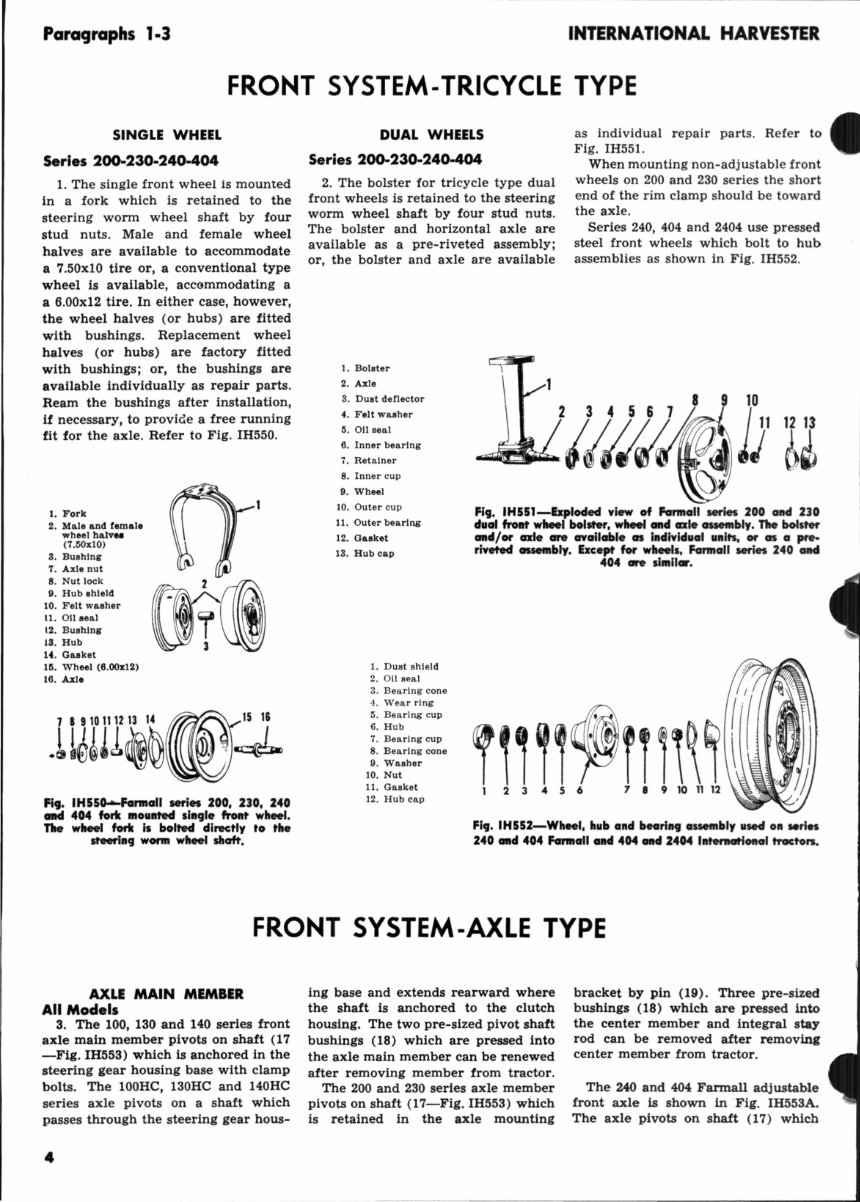
Paragraphs 1·3 INTERNATIONAL HARVESTER FRONT SYSTEM-TRICYCLE TYPE SINGLE WHEEL Series 2()()..230-240-404 1. The single front wheel is mounted in a fork which is retained to the steering worm wheel shaft by four stud nuts. Male and female wheel halves are available to accommodate a 7.50x10 tire or, a conventional type wheel is available , accommodating a a 6.00x12 tire. In either case, however, the wheel halves (or hubs) are fitted with bushings. Replacement wheel halves (or hubs) are factory fitted with bushings; or, the bushings are available individually as repair parts. Ream the bushings after installation, if necessary, to provide a free running fit for the axle. Refer to Fig. IH550. 1. Fork 2. Male &rid femal. wheel halv .. (7.50xl0) 8. Bushing 7. Axle nut 8. Nut lock 9. Hub ahleld 10. Felt washer 11. 01\ aeal 12. Bushing 18. Hub 14. Gasket 111. Wheel (8.00x12) 16. Axle 1 I ,,01'12" " ~15 11 .LI~~U~~~r~ Fig. IH55o-Farmaii series 200, 230, 240 CIItCI 4114 fork moulltecl IllIgle front wheel. TIle wheel fork II bolted directly to the st-tllg worm wheel shaft. DUAL WHEELS Series 200-230-240-404 2. The bolster for tricycle type dual front wheels is retained to the steering worm wheel shaft by four stud nuts. The bolster and horizontal axle are available as a pre-riveted assembly; or, the bolster and axle are available 1. Bolster 2. Axle 3. Duat deflector 4. Felt waaher 5. 01\ seal 6. Inner bearing 7. Retainer 8. Inner cup 9. Wheel as individual repair parts. Refer to Fig. 1H551. When mounting non-adjustable front wheels on 200 and 230 series the short end of the rim clamp should be toward the axle . Series 240, 404 and 2404 use pressed steel front wheels which bolt to hub assemblies as shown in Fig. IH552. 10. Outer cup 11. Outer bearing 12. Gaaket 13. Hub cap Fig. IH551-Exploded vl_ of Farmall series 200 and 230 dual front wheel bolster, wheel GIld axle assembly. The bolster GIld/or axle are avallabre as IlIdlvldual ulllts, or as a pre- riveted assembly. Except for wheell. Farmall series 240 IIItd 1. Dust shiel d 2. on seal 3. Bearing cone 4. Wear ring 5. Bearing cup 6. Hub 7. Bearing cup 8. Bearing cone 9. Washer 10. Nut 11. Gasket 12 . Hub cap 404 are Ilmllar. Fig. IH552-Wheel, hub and bearlllg assembly used 011 series 240 Gad 404 Farmall GIld 404 and 2404 IlIternatlonal tracton. FRONT SYSTEM-AXLE TYPE AXLE MAIN MEMBER All Models 3. The 100, 130 and 140 series front axle main member pivots on shaft (17 -Fig. IH553) which is anchored in the steering gear housing base with clamp bolts. The 100HC, 130HC and 140HC series axle pivots on a shaft which passes through the steering gear hous- 4 ing base and extends rearward where the shaft is anchored to the clutch housing. The two pre-sized pivot shaft bushings (18) which are pressed into the axle main member can be renewed after removing member from tractor. The 200 and 230 series axle member pivots on shaft (17-Fig. IH553) which is retained in the axle mounting bracket by pin (19). Three pre-sized bushings (18) which are pressed into the center member and integral stay rod can be removed after removing center member from tractor. The 240 and 404 Farmall adjustable front axle is shown in Fig. IH553A. The axle pivots on shaft (17) which
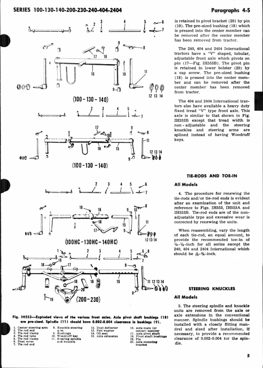
SERIES 100-130-140-200-230-240-404-2404 3 ! 4 I 5 0--6 6 -J--7 ~!IJ (1 ~~ 9 d ~8 II ~ 17 18 ~! I 11 ~I U 16 @ (g~ 10 '9' 9-{] (100 -130 - 140) 12 13 14 2 3 4 5 .. & ~=~ , ! ! l ! -J-7 17 9 ~ 0 U :P~181 d J [::::~S U'" ~ !'Tl "'-er-8 [ 1 o 9~ (100 -130 -140) 2 ~=~ &~, =---"/~ 3 4 5 ........ 6 I ='===\ -J-7 12 13 14 'b' 1~~ 2 3 4 5 ~8 ~Gq"F==~~~ iB A~--=====I = & ==::::!:'="'" ~-A-7 lB-<,(1"" 17 \ 9~ .Qdil----f- .~. '~~1 ' 8 ~. \16~ ~ b !oJ ~ _~ <If "11 " " II 11121314 ~d-20 9,tJ)l) to 11-19 ~ (200-230) Fit. IH553-Exploclecl vle"1 of the various frollt CDCln. Axle pivot sIIaft btllhl. nl) are p,...Iixecl. Spl ndle (11) Iho.ld have 0.002·0.004 cleornce I. btllhlllCJl (9). 1. Center .teerln~ arm 2. Tie rod end S. Tie rod clamp 4. Tie rod tube Ii . Tie rod clamp ~. Dult cover 7. Tie rod end 8. Knuckle ateerlng a: ·m 9. Bushings 10. Woodruff key 11 . S l. eerlng aplndle and knuckle 12. Dust deflector 13 . Felt waaher 14. 011 oeal Iii. Axle extenalen 16. Axle main (or center) member 17. Axle pivot ahatt 18. Pivot ahaft buahlop 19. Pin 20. Axle mOQDtlDc bracket Paragraphs 4-5 is retained in pivot bracket (20) by pin (19). The pre-sized bushing (18) which is pressed into the center member can be removed after the center member has been removed from tractor. The 240, 404 and 2404 International tractors have a "V" shaped, tubular, adjustable front axle which pivots on pin (17-Fig. IH553B). The pivot pin is retained in lower bolster (20) by a cap screw. The pre-sized bushing (18) is pressed into the center mem- ber and can be removed after the center member has been removed from tractor. The 404 and 2404 International trac- tors also have available a heavy duty fixed tread "V" type front axle. This axle is similar to that shown in Fig. IH553B except that tread width is non - adjustable and the steering knuckles and steering arms are splined instead of having Woodruff keys. TIE·RODS AND TOE·IN All Models 4. The procedure for renewing the tie-rods and/or tie-rod ends is evident after an examination of the unit and reference to Figs. IH553, IH553A and IH553B. Tie-rod ends are of the non- adjustable type and excessive wear is corrected by renewing the units. When reassembling, vary the length of each tie-rod, an equal amount, to provide the recommended toe-in of 1fs-%-inch for all series except the 240, 404 and 2404 International which should be /a--%-inch. STEERING KNUCKLES All Models 5. The steering spindle and knuckle units are removed from the axle or axle extensions in the conventional manner. Spindle bushings should be installed with a closely fitting man- drel and sized after installation, if necessary, to provide a recommended clearance of 0.002-0.004 tor the spin- dle. 5
Pa"'9raph5 6-7 STEERING GEAR Ser ies 1 00-13C)..140 The non-(td.JWltab~ I'HrlDq qear ia locat~ wlthJ..Q the It .. ring 9~ hou.mq ( 5-Fig. IHSS4j wh1ch ia bolted to the front fo c. oJ lb. engine. Th. front <nle I UPport (aIMring' q.cQ' hou.\nq ba .. ) 1a bolted to the lower portion of the ItHrlDq qeaI bou.lDq. StMI- lDq arm (I6) b retained to the Melor IIhcdt flD) by 0 nut. 6. REl'IfOVE AND REINSTALL. To remove the steering gear housing, front axle support (steering gear housing base), axl e and wheels as an assembly, proceed as follows: Remove hood, grille and radiator, and jack up front of tractor to remove weight from front wheels. To prevent steer- ing gear housing from tilting when housing Is disconnected from engine, place wood wedges between axle and steering gear housing base. Disconnect the head light wires and remove the radiator drain cap and pipe . Remove generator, reg ulator and mounting bracket from engine. On Hi-Clearance mode b, unbolt pivot s haft from clutch housing. Rem ove the s teering worm shaft . Remove the bolts retaining the steering gear ho using to the engine and move assembly away from tractor. Reinstall the unit by reversing the removal procedure. INTERNAnONAL HARVESTER 5 19 5 . ~ 4 1:1 3 00 ~ =;J 7. OVERHAUL. The steering gear unit can be overhauled without re- moving the assembly from tractor . Re- move s teering wheel and beari ng re- tainer (4-Fig. IH554) . Rotate worm and shaft (1) forward and out of housing (5). The pre-sl.zed worm bushing (20) and seal (21 ) can be re- newed at this time. Install seal with Up of same facing Inw a rd to ward Fi g. IHS53~bplocMd ...... . f _'" 240 .IMI 404 1.... ,..rI ... 1 fnNIt . to. 1. StNrlnc knuckl . 2. W oodru U k.y 3. Folt "' .. h.r ~. Thruot ~.rlni: ~. Du. hln. 6. Alii . nt.nolon 8. RI.ht hond IINnn. um g. Tie- rod !G. B.ll .... ,k. t II. 8tor rod bo ll 12. Shim 13. Sock., ea l> U. l..ock pla t. . '~ =~1=!-b-7 13 14 ~ ~ FIg. IHSUA-b plod'" 'flow .f lito adlll~blo wJd. trOllt CDI. IIsM 011 FanII.1 240 oM 404 Mrin troct. n, lotor t. FIg. IH5S) f or I ..... 6 15 . Clam p lG. O .... N tmlns 11. Phot pin IS. Bu.ItIDS 19. P'1'onl &:11,1. 2(1. Lower boloto r 22. TI.·rod end 23. Duat (lOVe r 24. TI.·rod tu~ ~. Cl .. ml> Z6. TI._ rod .nd 21. Lott It&nd .tMrinl .. rm jears. Use tin Ileeve or sblm stock when installing the worm sbatt to avoid damaging the .eat To remove sector (9) and shaft (10) , remove axle assembly from tractor and dis- connect steering arm (16) from the shaft. Remove the Iteerinj jear hous- ing base r etalninj' cap screws and re- move tbe bale . Pre-sued bushing (11) and seal (14) can be renewed at this time. I nstall seal w ith Up of lI&tne facing the gears. Remove the three bearing r etaine r ca p screws and p ull secto r, shaft and bearin&' asaembly from the bowing. To separate the assembly, remove map ring (6). Reassemble the ,ear unit by re- versing the di sassembly procedure and use tin sl eeve or sbIm stock wh en auembllng t be steerin&, gear howiOi' bue to the Iteerin&, gear howln, to avoid da magin, s eal (14).
SERI ES 100.130-140·200-230-240-404-2404 Paragraph 8 Serl e, 200-2JO..2,40-4C)4 Farmall The .teering worm and .. arm ",heel me L ocaied in the ItHrin<;l gear holi&l..llq. which III belted to the bont I<lce d the eDqiDe. Th. boline, Of ",h •• l fork ia l8Iaineci directl y to the 10, .... , portloll 01 the atMriDq ... arm wheel abaft by lour Il ud nut.. On Cldju.lable g:x}. mod.t.. the ctont ... It",ing c um ~ bolted \0 the lowe, pon J.on 01 Ihe worm ""bMl .hoh. and tb. O:l.lll lDClunliaq brocket t.. r .. loln.d to the l1eerinq gear hOlaine, by lour c;ap IJCJn.... The unit ii, no n-odj us tabl e; bow- ..... r .• ~ ... IT. bockkllh b-ttween the worm and wOrm ", heel can be ptlnlaUy correc1ed hy changing the paaUilo 01 the WO rm "'bee1 on Ihe _ann wheel .halt 'pUn". 10 01 \0 bring UD,",ora teeth ot the ""arm ",hMl into mel h .... ilb tb •• teenng worm. 8. REMOVE ANI) Rt :I NSTA - ' ,. To r emove the Iteerlnf: gear hous ing an, 1 front axle and s upport, bolster or whee l fork as an assem bly, proceed as f ollows: Remove h ood, '!Tille anrl radi- ator. On s eries 200 and 230, remove I ~ =--.J 1 34 ~~I/ • 10 . 19 .-<1 C::-s ~- 7 C~ B ~ 9 IB jJ- - 10 17 - 1 0- 11 () -11 ~~ 15J;;- 13 , ::.tk==:'~ IS "'-~ fiv. IH 5S4-Ser1fl 100, 130 olMl 140 ..... ,· I . ... 0-' .. d _ km4 parts.. n.. __ .. VH, .'" o. hl ... h c.leara~ 1IHMkI' I, ~.I. Iort, c.HUntC:t.d. I. Wo"" and II\ . rt ". B·~.hll\S •• "'ri~ ". Ouhl .. N •• " 0.. •• 110".1,.. b .... ,. fI.tolner ". OU .. oJ 5. 0. •• ho""ln .. ". C..nl lr .c .. rl .... Inn e SniP .1"1 , Woo4ru lt k.,. ,. Burt". " Woo4ruH klY • B .. rln ... otllne r , 8. 0., •• 1 pin 0 St<:lor " a".hl.,. " s..:to r I h.tt ~1. ~, ~ generator, re,(Ulator and mou nUn, brack et assem bly fro m en &,lne. Looaen st eerina Ihaft , upport, then discon- nect the s~ring s haft front unive rsal joint, and p ry un iversa l joint rear- ward and oft the steering worm shatto Remove radiator drain cap and pipe. Place jack unde r torque tube (clutch howlng ) and r emove weight from f ront wheels. Support steerina' gear housing and remove 11 12 15 6 ____ ~ 0. 13 '!t(o JS .' , " . " 57 56 55 59 housing to ena'ine retaining bolts. Jack up tractor bi&,h enough lor cranluhatt pu ll ey to clear steering gear howing and move assembly away from tractor. NOTE: On 404 model s equipped with power s teer in&" it will also be necessary to disconnect hydra ulic lines from oll cooler and loosen the line cUps .0 lines can be puUed outward. 45 61 63 ~ • -- 65 49 0- 67 S · 68 19 ' 69 ~ 70 0- 51 0- 71 ~ 53 I FI ... . IHUS-bpl"" . Ie ... of FmmaI1 ..rift 200, 230, 240 ... d 404 stHri.9 9"', lnet ot I .... .,. ~ ....... tile pam .sed ....... ,1 .9 9Ht' of 240, 404 aH 2404 h.t. "..,I .... MriH. n.. .. I, COlI 1M' 0., .... _' ...... "",oft r_ .., I.... o-r lI ouII1I9 ITo... n oc' .... 1. aeln"" ( 1U'Ion) ... Worm .e.r 57. nurlnc ... toln .. ~. Wonn ... 1\ .. 1 IhIft •• Uppe r ''' PJ)O t'l .nd .I\.tt ". Wo'm bUII,IntI' uPiM r belrl,.. -tlld .. Lo .. .r ""!>pori I ;. Woodrutt k ly M. W"rrn " Wonn Ih.1t .. II 00. BUlh!nc ... ~4aPtlr MI.OnINI ". Hunn; 42. 8t .. rln, Irm .. Worm .. ~.~. BI. 81lttlnll: crank r.,_ r.llht " Belrl,..c~ , .. Worm .~ .. 1 b •• ckot .. !Ju r ln .. cq • 44 ._1 oho/loll 1 .. 1 ". Unl~e ... l join t 5. Be.rln, ". St .. rtn ...... . ~. Wonn .. h .. 1 Ih.tt Ih .. " .nd yoke " B-a.l ... c .... houll", M. Be. M .... ". 'I .. nne Ih l tt c<>vo •• 11' .. .. . Worm nul OOInle . _ Mnc 71. Belfinc cqe """I., 7
Para9.aphs 9- 11 9. OVERHAUL. The steer ing gear unit can be overhauled without re- moving the assembly fr om tractor. To r emove the steer ing w orm, pro- ceed as tollows : Remove g rille and drain steering ,ear hous ing, Loosen 5teering shaft support, then discon- nect the steer ing shaft front universal joint, and sUde universa l joint rear- ward and oU the s teering worm s haft. Remove Woodruff key from worm shaft. Remove both starting crank bracket front r etaining cap screws and block - up between bracket and stee r- Ing gear housing enough to permit WOfTI\ to come out. Remove steering worm bearing retainer (:>7 - F ig, IH:555), and turn worm forward and out of howlng. Worm bushing (58) and worm shaft oil s eal (60) can be renewed at this time. Irutall worm shaft oil seal w it h lip of seal faelog Inward toward s teering gean!. Use a tin sleeve or s him stock when rein- stalling worm shaft to prevent dam - agi ng the seal. To rem ove worm s haft ball bearing, r emove cotte r key and nut, and bump worm shaft ou t of bearing. To rem ove the steer ing worm wheel and ,haft assembl y, proceed as fol- lows: Remove grille and drain steerlnJ: gea r housln&,. Jack up tractor under torque tube (cl utch housing) a nd re- move bolster or wheel fork on tricycle type models; or, on adjustable axle versions, disconnect the center steer- Ing arm from worm wheel shaft, re- move four axle mounting bracket to steering gear housing r etaining cap ,crews and move axle and wheels as - sembly away from tr a ctor. Remove the four worm wheel sh aft lower bearing cage and cover retai ning cap fI,. IH556--Seorift 200, no, 240 .-d 404 (FarMolli lteer'" WorJII w .... , IIH Ihcrft _Itl, ..... 0ftCI fr_ tile 1teM1 ..... r a. •• II.,. T1Io ... It ce .. be dl_ltlod eftef- romo'll .... tu4 1'41. s.. .... d '.r PI,. IH555 . • screws, and bump entire assembly out of stee r ing gear housing. The unit Is shown removed in Fi g. m~56. To dis- assemble the unit , r emove nut fr om stud ( 64 ) and pull out the stud; place assembly on a su itable pres5, and press beari ngs and worm wheel off ot worm wheel shait. At this time, w orm wheel s haft lower bearing and 011 seal (!i I- F ig. IH!i5!i) can be r enewed. In- sta ll oil seal wi th Jlp of sea l facing up tow ard worm wheel. Use a tin sl eeve or s him stock when re i nstalling worm wheel shait to prevent d amaging the sea l. Reassemble the unit by reversing the disassembly procedure. Series 240-404-2404 Intemational Tho s t .. ring worm <md worm whool oro locoted in tho . t .. ring 900T houdncJ which II bolt ed to tho fr olll f oco of Iho OllqlnO. The contor steering arm II keyed \0 tho low~r portion of the worm wh .. l shcdt and the axle support (lowor bobtor) 111 rotained to tho sleering gOOT howd.n9 by four etIp lICTews. Tho Uilit II IlOn-adJuatobio. 10. REMOVE AND REINSTA. LL. The stee r ing gea r housing, lower bol- ster and front axle assembly can be removed with radiator Install ed; how- eve r, some m~chanics prefe r to rem ove the radi ato r. To remove s teering gear housing with radiat or attached, pr oceed as fol_ low!: D rain cooling system, rem ove hood, and disconnect uppe r and lower radiator hoses. Disconnect the bead- " •. IHSSU.-Yi_ lhow- i., _i" 240 I.-..na- tI ... 1 wlta. fnHIt axle, froIIt boll t9r cntd radi ..... re. .... od as e ,tilt. Series 404 cat4 2404 oro IIIIIlIer. INTERNATIONAL HARVESTER li ght wires, then remove cap screw retaining radiator brace to the rmostat howing. On 240 series, loosen &,en- erator adjustment, then unbolt fan • blades. Leave blades resting in fan shroud and remove wat er pump pulley. On ~ and 2404 series, dis.- connect fan shroud from radiator. Drive roll pin from forward yoke of s teering shaft universal and remove cap scre ws from stee ring shaft center bea ri ng. Drive front universal from steering worm shaft. Place wood blocks between steerln, ,ear housing and ax le to prevent tipping, then un - bolt stay rod bracket from cl utch housing and the steering ,ear housing from front of engine. Ral.te enatne until crankshaft pulley will clear steer ini gear hoWini, then roll com- plete assembly fr om tractor. See Fli. IH5!i6A. NOTE: On 4W and 2404 models equipped with power steering, It will also be n~ to dilconnect by- draullc lines !rom oU coo ler and loosen the line clips 10 lines can be pulled outward . 11. OVERHAUL. The lteerlni iear uni t can be overhauled without re- moving the asoombly from tractor. To remove the steer ing worm, pro- ceed as followl: Remove grille and side s heet mou n ting bracket with l ow- er grille pan attached. then drai n steering gear housln i. Di.lCOllnect the stee ring shalt front universal from w orm s haft and the steerlni shaft center bearing from clutch housing. Drive universal from worm shaft and remove the Woodruff key. Remove
SERIES 100·130·140·200-230·240·404-2404 Para<)raph 12 t he steering worm retainer (57- Fig. IH555 ), and turn wonn f orward lind out of housing, To r emove the blill b,~arillg ( 55), re- move cot t er key lind nut and bump w orm sha ft out til bearing . Worm s haft bushing (58) an.1 o il seal (60) can be renewed a l. thi s time. Ins tall worm shaH oil seal wl lh lip of same facing inwa rd toward sleering gears. Use a tin sleeve or s him stock when reinstalling w orm s hllH to prevent damaging the sea l. To remove the stee r ing worm wheel FI, . IH5UI-YJew pow. I .. w_ wit..! _bly of I., .... IGHI .odel.,... .0Q4 "- ---. ,... 1I08s1!t9. HOM pMltiOfl of Gd.., _ t op .we of wonn wlleel. .. ~. SI .. . lnl ann ".1 C~~. 46. W or m Ilear 4' . ""b l'l~ •. and s haft assembly, proceed as follows: Remove grille and drain stee ring gear housing. Place a jack under torque tube (cl ut ch housing ) , d isconnect ce n- ter stee r ing arm from worm wheel s haft, then u nbolt lower bolster from stee ring gea r h ousing. Di sconnec t s tay rod bracket fr om clutc h bousing, then raise tra ctor an d roll front axle as- sembly f or ward . Unbolt worm wheel cage from steering gear housing a nd remove cage, worm wheel and adap tor as shown In Fi g. lH556B . Relet also to Fig. IH555. Remove eenter stee r ing a rm (42) and withdraw worm wh ee l and shah (46). Bushing (40) and 0 11 sea l ( 44 ) can be renewed at this time. 011 seal Is Installed w ith lip of same facing toward inside of steering gear hOllsing. When reinstalling cen ter stce ri ng ar m, torque the retaining nu t to 200-2SO n . -Jbs . Clamp s teering arm in a vise while li ghten ing nut; DO NOT use worm wheel as a slop. NOT!.: A new hOldened Woodrull by (47 - rl'l . IH5SS ) mUll be inatalled In aU Inter· nOlional 240 IroC1 o .. prior to ch.:aala .. rial number 4766. The new key II ldentlliMl. by CIOll·holch (lrnurUnq ) lIIar\u on Ih. flat ed'le. If, when liqhlenlnq the Ite .. lnq arm reto:in· Ing nUl, a COlleUallon 01 lhe nul d ... not cL\'ln with the COlier pin hoi" at '10m. point belween Ihe .podI lod 200·250 ft·u... lorq\le, continue 10 tlghlen tb e nUl . Do not bock-otl (1OO1en) nu t to obtain ailqnm"nt. When reinstalling the worm wheel assembly. be su re larie diameter ot adapter (spacer) ( 48 ) 15 on t op side as shown In Fig. IH556B. POWER STEERING Po..... I'eerinq I• . ]vaibbl. 01 optlOI!oQ\ equipment 10. ..ri.. 240. 4 04 (IIId 2404 l.acIO.. . Fcumall mod.1 I'(lct on utl1i~. a torque gllnll,ollng l.<olt (fig . IH- 5S6C) whi ch "PpU .. th. ~-ow.r ., "rlnq ou.ll l dirediy to the lleering .hoft . InternCltlonol model tractor_ 1.1" 0: 101(:1)' valv.. which hos the lame oonnq",otien 01 th. torque qene.allnq unll. and a hydraulic pow. t Klet.inq o;yllnde •. Th. power " .. rinq a .. 111 Fiq. IHS56C - Yi_ 5ho",ilq locatioo of power _ ..... 1 .,9 "., It fOf' r otory '10.1'1.1 .. traoc:IO" with FoG .....• Ite. , 1"9. on Inlernatioaru lIIod.] tr acto.. ]1 crppllod 10 the Ironl ccde Iteerin'l lLnko:q •. Prelluri led oil uMet to operate the pow.r .te"rlnq If.lelll i. provided by the Ilaetor hydraullc .y.I.III. The ao:mo low.r bol ."r and lleerinq mecho:nllm tl u.ed r"lendl ... of whether the traclor doel or doel not have power lleerinq. The power unit (f anna]]), or 10t(ITy '101'1' (International ), 1II0unt. In the II .. rin9 .ha ft lower .upport and replac .. th. upper IUp' LUBRICATION AND BLEED IN G Serle. 240-404-24t)4 12. The tra cto r hydr aulic system Is the sou r ce of flui d supply to the power steering system. Whenever the power st eering oil lines have been disconnected, reconnect the oil lines, fill the rese r voir and cycle the power steer i ng sys t em seve r al times to blee d pori Uled on traclorl without power ""ring. any ai r from t he system. Fh~, IH556D-SclMlllatlc iIIudratiOft of tIM pow .. It.erlll9 f low cOIIt rol '1111'1' lIIed Oft "'"" 2.. 0. Th. fI_ cOIItr'IIl '1~" i.ot iJf i .. tile 2 1 /1.) 9"" req"i"-eIIf of til. pow., ._1119 syshtn be-i'ore 1liiy oJ] f]owl to lite Hydra· Touch ays........ Melering coi&c in v. l"" pilton end Auxili...ry ... !tt y T 0 ~oir val "" I".. .. ~ . ,..- To hydrHouch l yOf em Mo"'" flow 10 tl-'"g .... Iv, 9
Para9raphs 13·14 OPERATING PRESSURE, RILIEF VALVE, FLOW CONTROL VALVE Se r ies 240 13. Working fluid for the hydra u lic power stee ring system Is supp lied by the same pump which powe rs the Hydr a-Touch system. Int erposed be- tween the pump and the Hydra -Touch s ystem is a flow control valve mechan- Ism which is shown ichematically in Fig. IH556D. The small metering hole in the end ot the flow valve piston passes between 2Y.: to 3 gallons per minute to the power steering system; but, since the pump s upplies consid- erably morc than three gpm, pressure builds up in tr on t of the piston and moves the piston, a ga inst spring pres- sure, until the ports whi ch s upply all to t he Hydra-Touch system are uncov- ered. The ste ering system, therefore, 11 It 211 11 16 Ie{~fo~~ 21 22 24 ___ 15--! " -. FI, . IH556E--E.lploded "low of tho '~II- kItw, ..... ,. _d flow cHfToI "01". lIad .. .1140 MOdet5.ittI Hydro-Towell ~_d po_ I tMriltf. TIle 0 ... 1110...., ..Jet, "01". (14, 15 OM 16) protects all, tho pow. , __ I .. .,... . Val .... Ill ) " lot errail_ .. _ IOPCIroNiy. I. Cov.r 2. 00 ... 1 pIn •. Guk.t 4. s. .. t rin. $. R .... l .. to r v .. lv. platon t. Reculator .. al ... "" 1. 8tMl b.n S. Ball tid.,r II. lIan I"!du apr!",," 10. 8&l el)' valVo. mn~ II. Satet)' vatu ~"~ 11. 8prlnc .. talner 11 . So .. P ti .... 10 U. Satet)' va]ve pl.,on l~. V.Iyallou , ln, 1ft. a .... ] tina- 11. Plu. 18 . Snap rlnll" 111. Rat.ln er 20. 8< ... 1 rlna 21 .• 10" Conlr Ol .... Iy. apr!",," ;:2. no .. oontl"Ol val ... 23. Ro.talner 24. Auxlll.O' .. t.t)' .. alu ".ti.., 2~. St Ml1ai1 't<II. PlUof FI, . IH556F - Shllt - oH " 01,,. OR prftl.r . 9090 illitoliotiol dio,ralll for f rOllbl . dl ootlng tho pow- Of IteOfln9 $ ,.t. 1Il on .et"i es 240. 11 SllEIIN; YAm r ccei ves priority and the fluid requlre- mcnts of the steering system are satis - fied before any oil flows to the Hydra- Touch sys tem. The auxlllary safety valve for the power s teering system maintains a system ope r ating pressure of 1200-1500 psi. The components of the flow control valve are shown ex- ploded from the valve housing In Fi i. IH556E. A pressure test of the power steer- Ing circuit will disclose whether the pump, safety valve or some other unit in the system Is malfunctioning . To make s uch a test, proceed as Collows: Connect a pressure test gage and s hut- aU valve In series with the line con- necting the flow control valve to the steering valves as shown in Fig. IH- 556F. Notice that the press ure gage is connected in the circuit between the shut-of! valve and the flow control valve. Open the shut-oU vaive and run engine at low Idle speed until oil is warmed. Advance the elliine speed to the specified high idle rpm, close the shut-off valve, observe the pres- sure gage reading, then open the shut- oU va lve. i.f the gage reading is be- tween 1200 and 1500 psi with the shut- off valve closed, the hydraulic pump and auxiliary safety valve are O.K. and any tr ouble is located elsewhe re in the system. IC the gage reading is more than 1500 psi, the auxiliary saCety valve may be stuck In the closed position. It the gage reading Is less than 1200 psi, r enew the auxiliary safety valve spring and recheck the pre ssur e read- Ing. If the gage reading is still less than 1200 psi, a faulty hydraulic pump is Indicated. For information on the r eiUlator , safety and flow control valve U5em- bly, refer to paragraph 131. $&rles 404·2404 14. Working fluid fo r the hydrauli c power steerini" system Is supplied by the same pump which powers the hydraulic system. Interposed between the pump and the hydraulic 11ft hous- ing Is a flow control valve assembly which Is shown in Fi g. IH556G. Pressurized 011 Is directed lirst to the now control val ve and the valve INTERNATIONAL HARVESTER R~Ul.I", s.n:rr ~ fLOW ctt; , PGl um Ma US1N' in turn directs the pressurized oil to the power steering circuit until the needs oC the power steering system are satisfied. Thus the power stec r lng system receives priority and Its re- qulrements satisfied before any oU flows to the hydraulic s ystem . Hy- drauli c pumpll of 9 gpm capacity are used on tractors with power steering while those tracto rs with no power s teering are equipped wIth 4 YI gpm pumps. A pressure test of the power stee r- ing circuit can be made a! follows ; Connect a pressure gage In seri es with the line connectJni flow control valve to power unit ( Farmall ) or rotary valve (International ) and be sure gage Is between flow control valve and shut-off valve. Open the shut-off valve and run engine at lo w idle speed until all is warmed to operat- ing temperature. Advance engine speed to high idle rpm, close shut - oU valve and observe gage reading which should be 13M-15M psi. Note: To preclude any poulbUity of overheatlni 011 or damaging hy- draulic pump, keep ahut-off valve closed on ly long enough to obtain gage readine. F19. IH556 Ci - Loccrtl .. of fl ow control ... al n .. ..04 ..,. 1404 Mrios tract ...... N .... r.I '-f "at .... pl ., . H . H)"Graul1c bo .. ,ln, M. Man!fold. P. PlUof V. Flo .. oontrol vo.lva
This professional technical manual contains service, maintenance, and troubleshooting information for your IH International Harvester 2444 tractor, covering all models, engines, trim, and transmission types. It is the same manual used in the local service/repair shop and is guaranteed to be fully functional without any missing or corrupt parts or pages.
Written by the manufacturers, this original workshop manual contains hundreds of pages of diagrams and detailed information for specific vehicle or equipment repair. It includes pictures and easy-to-follow directions on what tools are needed and how the repair is performed.
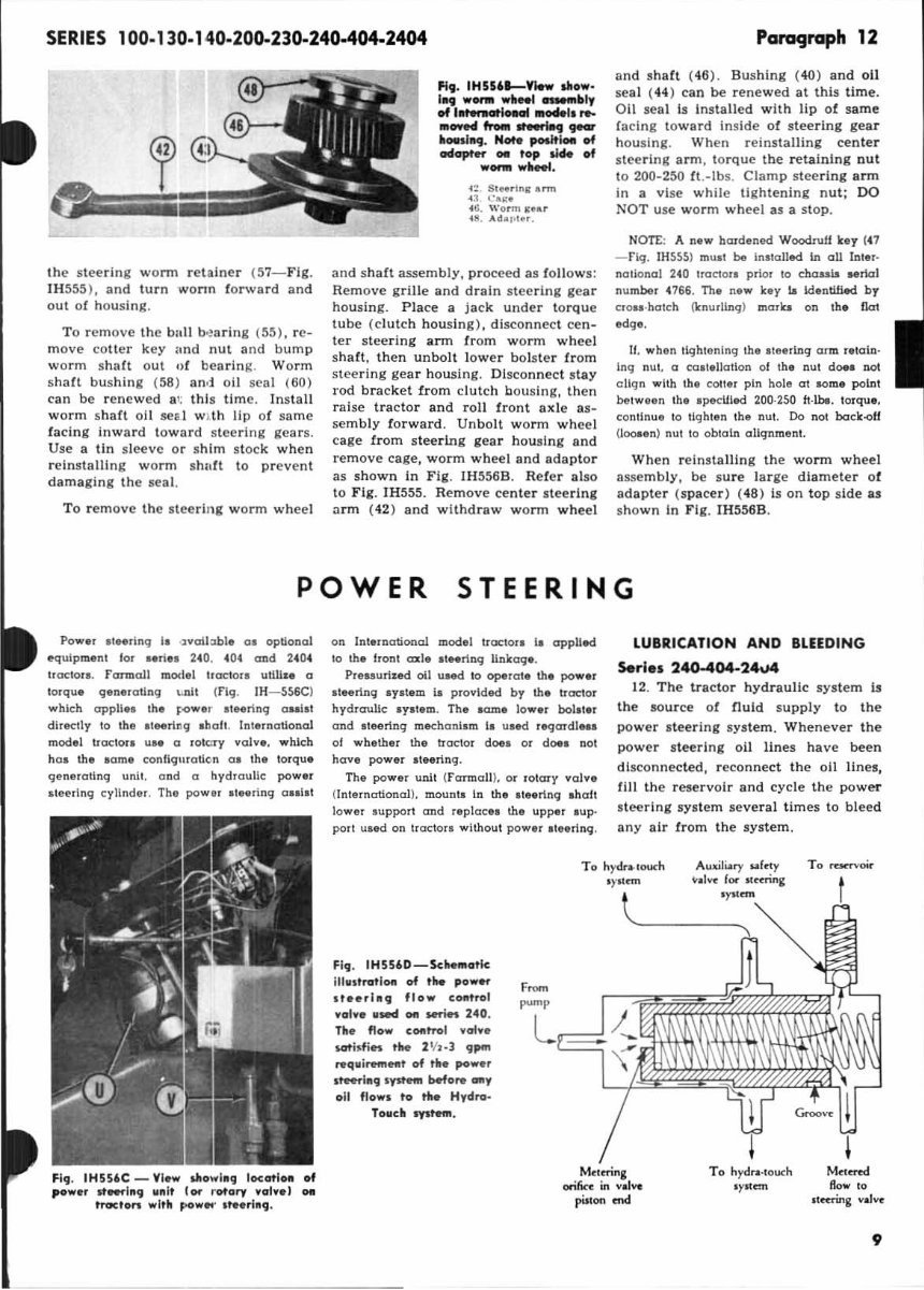
The manual covers the engine, lubrication system, cooling system, fuel system, disassembly and servicing, general, separation, clutch, transmission, drive chain & sprockets, rear axle, brakes, front axle, steering, shocks, body work, intake & exhaust, hydraulic system, electrical system, routine maintenance, advanced troubleshooting, and wiring diagram, plus a lot more info.
Having the manual in an electronic format is a huge advantage as you can simply print the desired section from your PC and dispose of it once the repair or service is completed. Whether using a paper manual or electronic version, you'll find the same features in both. The biggest difference is that you can download the electronic version straight to your computer in just seconds.
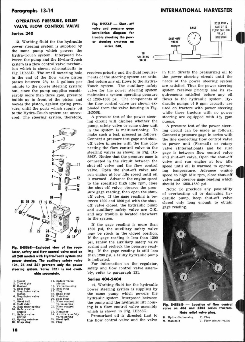
This workshop repair service manual contains detailed substeps that expand on repair procedure information, notes, cautions, and warnings throughout each chapter, numbered instructions, bold figure numbers, detailed illustrations, drawings, and photos, an enlarged inset to help you identify and examine parts in detail, and a numbered table of contents for easy navigation. It also makes it easy to diagnose and repair problems with your machine's electrical system, with troubleshooting and electrical service procedures combined with detailed wiring diagrams for ease of use.
File Format: .PDF
Language: English
Specifications: Full Printable
Zoom IN/OUT: Yes
Delivery: Instant
Requirements: Adobe Reader & Win
Compatible: All Versions of Windows & Mac
Recently Viewed
5,521,897Happy Clients
2,594,462eManuals
1,120,453Trusted Sellers
15Years in Business
Price:
Actual Price:
IH International Harvester 2444 Repair Service Manual