HOW TO USE THE INDEX: Suppose you want to know the procedure for R&R (remove and reinstall) of the engine camshaft. Your first step is to look in the index under the main heading of ENGINE until you find the entry “Camshaft.” Now read to the right where under the column covering the tractor you are repairing, you will find a number that indicates the beginning paragraph pertaining to the camshaft. To locate this wanted paragraph in the manual, turn the pages until the running index appearing on the top outside corner of each page contains the number you are seeking. In this paragraph you will find the information concerning the removal of the camshaft.
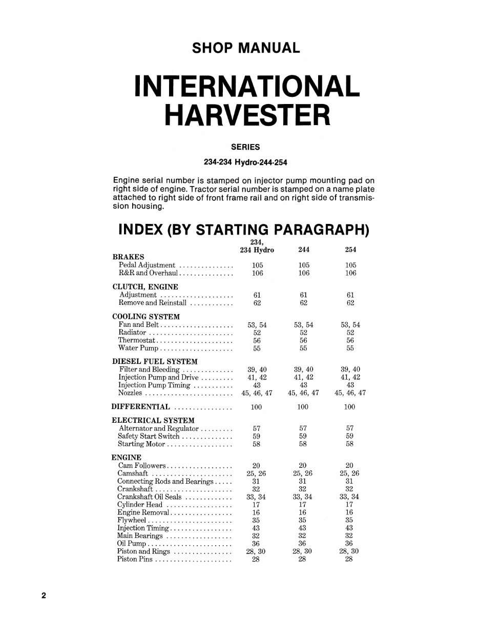
2 SHOP MANUAL INTERNATIONAL HARVESTER SERIES 234·234 Hydro·244·254 Engine serial number is stamped on injector pump mounting pad on right side of engine. Tractor serial number is stamped on a name plate attached to right side of front frame rail and on right side of transmis- sion housing. INDEX (BY STARTING PARAGRAPH) BRAKES Pedal Adjustment .............. . R&R and Overhaul .............. . CLUTCH, ENGINE Adjustment ................... . Remove and Reinstall ........... . COOLING SYSTEM Fan and Belt ................... . Radiator ...................... . Thermostat .................... . Water Pump ................... . DIESEL FUEL SYSTEM Filter and Bleeding ............. . Injection Pump and Drive ........ . Injection Pump Timing .......... . Nozzles ....................... . DIFFERENTIAL ............... . ELECTRICAL SYSTEM Alternator and Regulator ........ . Safety Start Switch ............. . Starting Motor ................. . ENGINE Cam Followers ................. . Camshaft ..................... . Connecting Rods and Bearings .... . Crankshaft .................... . Crankshaft Oil Seals ............ . Cylinder Head ................. . Engine Removal ................ . Flywheel ...................... . Injection Timing ................ . Main Bearings ................. . Oil Pump ...................... . Piston and Rings ............... . Piston Pins .................... . 234, 234 Hydro 105 106 61 62 53,54 52 56 55 39, 40 41,42 43 45,46,47 100 57 59 58 20 25, 26 31 32 33, 34 17 16 35 43 32 36 28, 30 28 244 105 106 61 62 53, 54 52 56 55 39,40 41, 42 43 45, 46, 47 100 57 59 58 20 25, 26 31 32 33, 34 17 16 35 43 32 36 28, 30 28 254 105 106 61 62 53, 54 52 56 55 39, 40 41, 42 43 45, 46, 47 100 57 59 58 20 25, 26 31 32 33, 34 17 16 35 43 32 36 28, 30 28
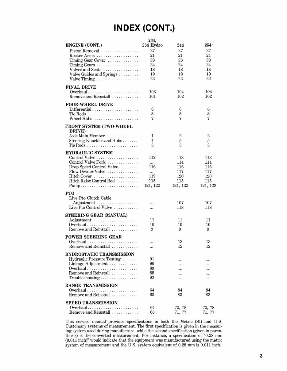
INDEX (CONT.) 234, ENGINE (CONT.) 234 Hydro 244 254 Piston Removal ................. 27 27 27 Rocker Arms ................... 21 21 21 Timing Gear Cover .............. 23 23 23 Timing Gears ................... 24 24 24 Valves and Seats ................ 18 18 18 Valve Guides and Springs ......... 19 19 19 Valve Timing ................... 22 22 22 FINAL DRIVE Overhaul ....................... 103 104 104 Remove and Reinstall ............ 101 102 102 FOUR-WHEEL DRIVE Differential. .................... 6 6 6 TieRods ....................... 8 8 8 Wheel Hubs .................... 7 7 7 FRONT SYSTEM (TWO-WHEEL DRIVE) Axle Main Member .............. 1 2 2 Steering Knuckles and Hubs ....... 4 5 5 TieRods ....................... 3 3 3 HYDRAULIC SYSTEM Control Valve ................... 112 113 113 Control Valve Fork .............. 114 114 Drop Speed Control Valve ......... 116 116 116 Flow Divider Valve .............. 117 117 Hitch Cover .................... 119 120 120 Hitch Raise Cemtrol Rod .......... 115 115 115 Pump .......................... 121, 122 121, 122 121, 122 PTO Live Pto Clutch Cable Adjustment ................... 107 107 Live Pto Control Valve ........... 118 118 STEERING GEAR (MANUAL) Adjustment .................... 11 11 11 Overhaul ....................... 10 10 10 Remove and Reinstall ............ 9 9 9 POWER STEERING GEAR Overhaul ....................... 13 13 Remove and Reinstall ............ 12 12 HYDROSTATIC TRANSMISSION Hydraulic Pressure Testing ....... 91 Linkage Adjustment ............. 90 Overhaul ....................... 89 Remove and Reinstall ............ 88 Troubleshooting ................. 92 RANGE TRANSMISSION Overhaul ....................... 64 84 84 Remove and Reinstall ............ 63 83 83 SPEED TRANSMISSION Overhaul ....................... 64 72,78 72,78 Remove and Reinstall ............ 63 71,77 71,77 This service manual provides specifications in both the Metric (SI) and U.S. Customary systems of measurement. The first specification is given in the measur- ing system used during manufacture, while the second specification (given in paren- thesis) is the converted measurement. For instance, a specification of "0.28 mm (0.011 inch)" would indicate that the equipment was manufactured using the metric system of measurement and the U.S. system equivalent of 0.28 mm is 0.011 inch. 3
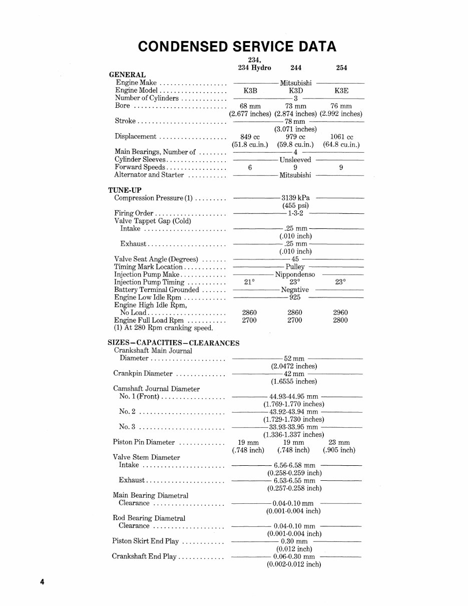
4 CONDENSED SERVICE DATA GENERAL 234, 234 Hydro 244 254 Engine Make . . . . . . . . . . . . . . . . . . . Mitsubishi ----- Engine Model. . . . . . . . . . . . . . . . . . . K3B K3D K3E Number of Cylinders . . . . . . . . . . . . . 3 Bore .......................... 68 mm 73 mm 76 mm (2.677 inches) (2.874 inches) (2.992 inches) Stroke. . . . . . . . . . . . . . . . . . . . . . . . . 78 mm ------ Displacement .................. . Main Bearings, Number of ....... . Cylinder Sleeves ................ . Forward Speeds ................ . Alternator and Starter .......... . TUNE-UP Compression Pressure (1) ........ . Firing Order ................... . Valve Tappet Gap (Cold) Intake ...................... . Exhaust ..................... . Valve Seat Angle (Degrees) ...... . Timing Mark Location ........... . Injection Pump Make ............ . Injection Pump Timing .......... . Battery Terminal Grounded ...... . Engine Low Idle Rpm ........... . Engine High Idle Rpm, No Load ..................... . Engine Full Load Rpm .......... . (1) At 280 Rpm cranking speed. (3.071 inches) 849 cc 979 cc 1061 cc (51.8 cu.in.) (59.8 cu.in.) (64.8 cu.in.) -------4 ------- -----Unsleeved ----- 6 9 -----Mitsubishi -----3139kPa 9 (455 psi) ------1-3-2 ------ ------.25 mm------ (.010 inch) -~----.25 mm------ (.010 inch) ------45------- ------Pulley ------ ---- Nippondenso 23° -----Negative ------925 ------ 2860 2700 2860 2700 2960 2800 SIZES-CAPACITIES-CLEARANCES Crankshaft Main Journal Diameter .................... . Crankpin Diameter ............. . Camshaft Journal Diameter No.1 (Front) ................. . No.2 No.3 Piston Pin Diameter ............ . Valve Stem Diameter Intake ...................... . Exhaust ..................... . Main Bearing Diametral Clearance ................... . Rod Bearing Diametral Clearance ................... . Piston Skirt End Play ........... . Crankshaft End Play ............ . ------52mm------ (2.0472 inches) ------42mm------ (1.6535 inches) ---- 44.93-44.95 mm ----- (1. 769-1. 770 inches) ----43.92-43.94 mm ----- (1. 729-1. 730 inches) ----33.93-33.95 mm ----- (1.336-1.337 inches) 19mm 19mm (.748 inch) 23mm (.905 inch) (.748 inch) ---- 6.56-6.58 mm (0.258-0.259 inch) ---- 6.53-6.55 mm ----- (0.257-0.258 inch) ----0.04-0.10 mm (0.001-0.004 inch) ---- 0.04-0.10 mm (0.001-0.004 inch) -----0.30mm ----- (0.012 inch) ---- 0.06-0.30 mm (0.002-0.012 inch)
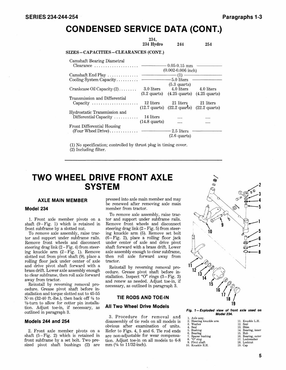
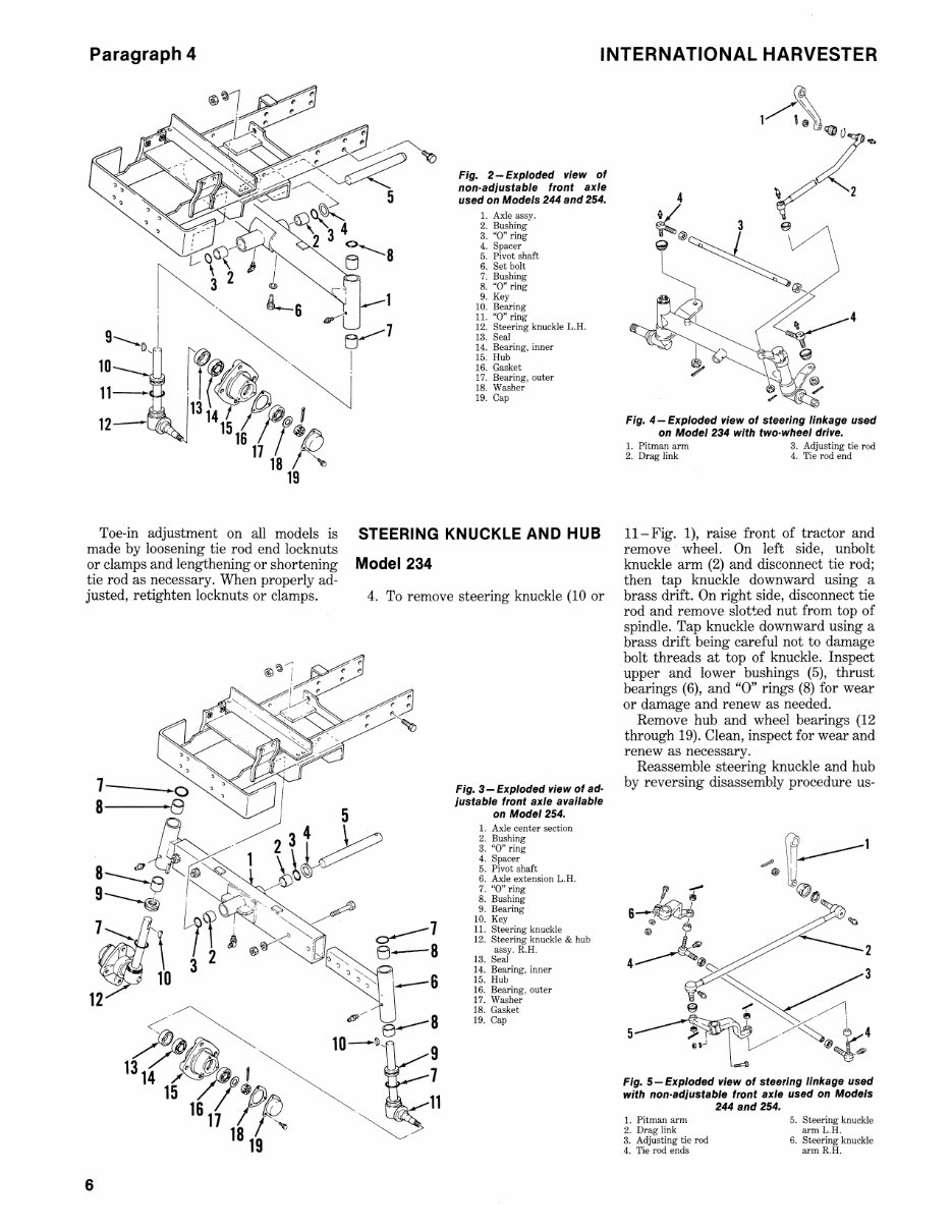
SERIES 234·244·254 CONDENSED SERVICE DATA (CONT.) 234, 234 Hydro 244 SIZES-CAPACITIES-CLEARANCES (CONT.) Camshaft Bearing Diametral Clearance ................... . -----0.05-0.15 mm 254 Camshaft End Play ............. . Cooling System Capacity ......... . (0.002.-0.006 inch) ------(1) ------ ------5.0 liters (5.3 quarts) Crankcase Oil Capacity (2) ....... . 3.0 liters (3.2 quarts) 4.0 liters 4.0 liters (4.25 quarts) (4.25 quarts) Transmission and Differential Capacity ..................... 12 liters 21 liters 21 liters (12.7 quarts) (22.2 quads) (22.2 quarts) Hydrostatic Transmission and Differential Capacity .......... . 14 liters (14.8 quarts) Front Differential Housing (Four Wheel Drive) ............ . ------ 2.5 liters (2.6 quarts) (1) No specification; controlled by thrust plug in timing cover. (2) Including filter. TWO WHEEL DRIVE FRONT AXLE SYSTEM AXLE MAIN MEMBER Model 234 1. Front axle member pivots on a shaft (9-Fig. 1) which is retained in front subframe by a slotted hut. To remove axle assembly, raise trac- tor and support under subframe rails. Remove front wheels and disconnect steering drag link (2-Fig. 4) from steer- ing knuckle arm (2-Fig. 1). Remove slotted nut from pivot shaft (9), place a rolling floor jack under center of axle and drive pivot shaft forward with a brass drift. Lower axle assembly enough to clear subframe, then roll axle forward away from tractor. pressed into axle main member and may be renewed after removing axle main member from tractor. To remove axle assembly, raise trac- tor and support under subframe rails. Remove front wheels and disconnect steering drag link (2 - Fig. 5) from steer- ing knuckle arm (5). Remove set bolt (6-Fig. 2), place a rolling floor jack under center of axle and drive pivot shaft forward with a brass drift. Lower axle assembly enough to clear subframe, then roll axle forward away from tractor. Reinstall by reversing removal pro- cedure. Grease pivot shaft before in- stallation. Inspect "0" rings (3 - Fig. 3) and renew as needed. Adjust toe-in, if necessary, as outlined in paragraph 3. TIE RODS AND TOE·IN All Two Wheel Drive Models Paragraphs 1·3 Reinstall by reversing removal pro- cedure. Grease pivot shaft before in- stallation and torqu~ slotted nut to 45-55 N'm (32-40 ft.-Ibs.), then back off 1/4 to Va-turn to allow for cotter pin installa- tion. A.djust toe-in, if necessary, as outlined in paragraph 3. 3. Procedure for removal and disassembly of tie rods on all models is obvious after examination of units. Refer to Figs. 4, 5 and 6. Tie rod ends are non-adjustable for wear compensa- tion. Adjust toe-in on all models to 6-8 mm (1f4 to 11/32-inch). Fig. 1- Exploded "lew of front axle used on Model 234. Models 244 and 254 2. Front axle member pivots on a shaft (5-Fig. 2) which is retained in front subframe by a set bolt. Two pre- sized pivot shaft bushings (2) are 1. Axle assy. 2. Steering knuckle arm 3. Washer 4. Seal 5. Bushing 6. Bearing 7. Spacer bushing 8. "0" ring 9. Pivot shaft 10. Knuckle R.H. 11. Knuckle L.H. 12. Seal 13. Shim 14. Bearing, inner 15. Hub 16. Bearing, outer 17. Lockwasher 18. Locknut 19. Cap 5
Paragraph 4 INTERNATIONAL HARVESTER Fig. 2-Exploded view of non·adjustable front axle used on Models 244 and 254. 1. Axle assy. 2. Bushing 3. "0" ring 4. Spacer 5. Pivot shaft 6. Set bolt 7. Bushing 8. "0" ring 9. Key 10. Bearing 11. "0" ring 12. Steering knuckle L.R. 13. Seal 14. Bearing, inner 15. Rub 16. Gasket 17. Bearing, outer 18. Washer 19. Cap Toe-in adjustment on all models is STEERING KNUCKLE AND HUB made by loosening tie rod end locknuts or clamps and lengthening or shortening Model 234 tie rod as necessary. When properly ad- justed, retighten locknuts or clamps. 4. To remove steering knuckle (10 or 6 0--- 7 B-B Fig. 3 - Exploded view of ad· justable front axle available on Model 254. 1. Axle center section 2. Bushing 3. "0" ring 4. Spacer 5. Pivot shaft 6. Axle extension L.R. 7. "0" ring 8. Bushing 9. Bearing 10. Key 11. Steering knuckle 12. Steering knuckle & hub assy. R.R. 13. Seal 14. Bearing, inner 15. Rub 16. Bearing, outer 17. Washer 18. Gasket 19. Cap Fig. 4 - Exploded view of steering linkage used on Model 234 with two· wheel drive. 1. Pitman arm 3. Adjusting tie rod 2. Drag link 4. Tie rod end ll-Fig. 1), raise front of tractor and remove wheel. On left side, unbolt knuckle arm (2) and disconnect tie rod; then tap knuckle downward using a brass drift. On right side, disconnect tie rod and remove slotted nut from top of spindle. Tap knuckle downward using a brass drift being careful not to damage bolt threads at top of knuckle. Inspect upper and lower bushings (5), thrust bearings (6), and "0" rings (8) for wear or damage and renew as needed. Remove hub and wheel bearings (12 through 19). Clean, inspect for wear and renew as necessary. Reassemble steering knuckle and hub by reversing disassembly procedure us- Fig. 5-Exploded view of steering linkage used with non·adjustable front axle used on Models 244 and 254. 1. Pitman arm 2. Drag link 3. Adjusting tie rod 4. Tie rod ends 5. Steering knuckle arm L.R. 6. Steering knuckle arm R.R.
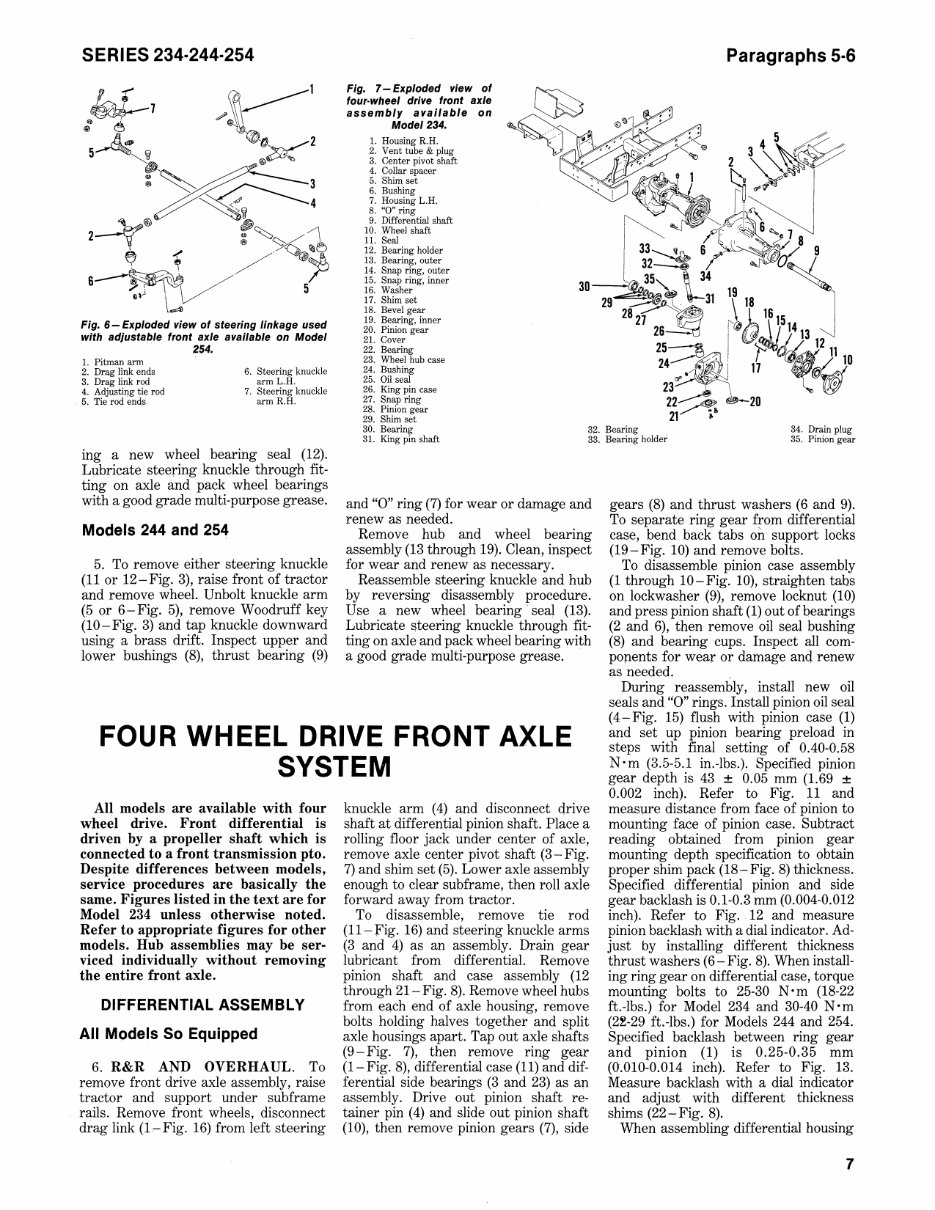
SERIES 234·244·254 ~~' 5A~i @"K2 r~~3 <4' 4 ~\I --»@ ~ 2 ~ ®~~l W /~~ --,. f" \ '&fV' /' 6 ":.) U 5 Fig. 6 - Exploded view of steering linkage used with adjustable front axle available on Model '. 254. 1. Pitman arm 2. Dr~g link ends 3. Drag link rod 4. Adjusting tie rod 5. Tie rod ends 6. Steering knuckle arm L.H. 7. Steering knuckle arm R.H. ing a new wheel bearing seal (12). Lubricate steering knuckle through fit- ting on axle and pack wheel bearings with a good grade multi-purpose grease. Models 244 and 254 5. To remove either steering knuckle (11 or 12-Fig. 3), raise front of tractor and remove wheel. Unbolt knuckle arm (5 or 6-Fig. 5), remove Woodruff key (10-Fig. 3) and tap knuckle downward using a brass drift. Inspect upper and lower bushings (8), thrust bearing (9) Fig. 7 - Exploded view of four·wheel drive front axle assembly available on Model 234. 1. Housing R.H. 2. Vent tube & plug 3. Center pivot shaft 4. Collar spacer 5. Shim set 6. Bushing 7. Housing L.H. 8. "0" ring 9. Differential shaft to. Wheel shaft 11. Seal 12. Bearing holder 13. Bearing, outer 14. Snap ring, outer 15. Snap ring, inner 16. Washer 17. Shim set 18. Bevel gear 19. Bearing, inner 20. Pinion gear 21. Cover 22. Bearing 23. Wheel hub case 24. Bushing 25. Oil seal 26. King pin case 27. Snap ring 28. Pinion gear 29. Shim set Paragraphs 5·6 30. Bearing 32. Bearing 34. Drain plug 31. King pin shaft 33. Bearing holder 35. Pinion gear and "0" ring (7) for wear or damage and renew as needed. Remove hub and wheel bearing assembly (13 through 19). Clean, inspect for wear and renew as necessary. Reassemble steering knuckle and hub by reversing disassembly procedure. Use a new wheel bearing' seal (13). Lubricate l'\teering knuckle through fit- ting on axle and pack wheel bearing with a good grade multi-purpose grease. gears (8) and thrust washers (6 and 9). To separate ring gear from differential case, bend back tabs oil.' support locks (19-Fig. 10) and remove bolts. To disassemble pinion case assembly (1 through 10-Fig. 10), straighten tabs on lockwasher (9), remove locknut (10) and press pinion shaft (1) out of bearings (2 and 6), then remove oil seal bushing (8) and bearing cups. Inspect all com- ponents for wear or damage and renew as needed. , FOUR WHEEL DRIVE FRONT AXLE SYSTEM During reassembly, install new oil seals and "0" rings. Install pinion oil seal (4-Fig. 15) flush with pinion case (1) and set up pinion bearing preload in steps with final setting of 0.40-0.58 N'm (3.5-5.1 in.-Ibs.). Specified pinion gear depth is 43 ± 0.05 mm (1.69 ± 0.002 inch). Refer to Fig. 11 and measure distance from face of pinion to mounting face of pinion case. Subtract reading obtained from pinion gear mounting depth specification to obtain proper shim pack (18- Fig. 8) thickness. Specified differential pinion and side gear backlash is 0.1-0.3 mm (0.004-0.012 inch). Refer to Fig. 12 and measure pinion backlash with a dial indicator. Ad- just by installing different thickness thrust washers (6- Fig. 8). When install- ing ring gear on differential case, torque mounting bolts to 25-30 N'm (18-22 ft.-Ibs.) for Model 234 and 30-40 N'm (2£-29 ft.-Ibs.) for Models 244 and 254. Specified baCklash between ring gear and pinion (1) is 0.25-0.35 mm (0.010-0.014 inch). Refer to Fig. 13. Measure backlash with a dial indicator and adjust with different thickness shims (22-Fig. 8). All models are available with four wheel drive. Front differential is driven by a propeller shaft which is connected to a front transmission pto. Despite differences between models, service procedures are basically the same. Figures listed in the text are for Model 234 unless otherwise noted. Refer to appropriate figures for other models. Hub assemblies may be ser- viced individually without removing the entire front axle. DIFFERENTIAL ASSEMBLY All Models So Equipped 6. R&R AND OVERHAUL. To remove front drive axle assembly, raise tractor and support under subframe rails. Remove front wheels, disconnect drag link (I-Fig. 16) from left steering knuckle arm (4) and disconnect drive shaft at differential pinion shaft. Place a rolling floor jack under center of axle, remove axle center pivot shaft (3-Fig. 7) and shim set (5). Lower axle assembly enough to clear subframe, then roll axle forward away from tractor. To disassemble, remove tie rod (11- Fig. 16) and steering knuckle arms (3 and 4) as an assembly. Dril,in gear lubricant from differential. Remove pinion shaft and case assembly (12 through 21- Fig. 8). Remove wheel hubs from e~ch end of axle housing, remove bolts holding halves together and split axle housings apart. Tap out axle shafts (9-Fig. 7), then remove ring gear (1- Fig. 8), differential case (11) and dif- ferential side bearings (3 and 23) as an assembly. Drive out pinion shaft re- tainer pin (4) and slide out pinion shaft (10), then remove pinion gears (7), side When assembling differential housing 7
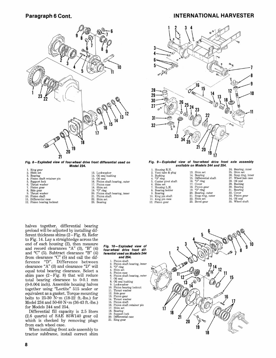
Paragraph 6 Cont. , ~\~ •• ~\\1312 ~~8 11 16 ~ 20 19 21 Fig. 8-Exploded view of four·wheel drive front differential used on Model 234. 1. Ring gear 2. Shim set 13. Lockwasher 3. Bearing 14. Oil seal bushing 4. Pinion shaft retainer pin 15. Oil seal 5. Support lock 16. Pinion shaft bearing, outer 6. Thrust washer 17. Pinion case 7. Pinion gear 18. Shim set 8. Side gear 19. "0" ring 9. Thrust washer 20. Pinion shaft bearing, inner 10. Pinion shaft 21. Pinion shaft 11. Differential case 22. Shim set 12. Pinion bearing locknut 23. Bearing halves together, differential bearing preload will be adjusted by installing dif- ferent thickness shims (2 - Fig. 8). Refer to Fig. 14. Lay a straightedge across the end of each housing (2), then measure and record clearances "A" (3), "B" (4) and "C" (5). Subtract clearance "B" (4) from clearance "C" (5) and call the dif- ference "D". Difference between clearance "A" (3) and clearance "D" will equal total bearing clearance. Select a shim pace (2-Fig. 8) that will reduce total bearing clearance to 0-0.1 mm (0-0.004 inch). Assemble housing halves together using "Loctite" 515 sealer or equivalent as a gasket. Torque mounting bolts to 25-30 Nom (18-22 ft.-lbs.) for Model 234 and 50-60 Nom (36-43 ft.-lbs.) for Models 244 and 254. Differential fill capacity is 2.5 liters (2.6 quarts) of SAE 85W140 gear oil which is checked by removing plugs from each wheel case. When installing front axle assembly to tractor subframe, install correct shim 8 Fig. 10- Exploded view of four· wheel drive front dif· ferentlal used on Models 244 and 254. 1. Pinion shaft 2. Pinion shaft bearing, inner 3. "0" ring 4. Shim set 5. Pinion case 6. Pinion shaft bearing, outer 7. Oil seal 8. Oil seal bushing 9. Lockwasher 10. Pinion bearing locknut 11. Thrust washer 12. Side gear 13. Pinion gear 14. Thrust washer 15. Pinion shaft 16. Pinion shaft retainer pin 17. Shim set 18. Bearing 19. Support lock 20. Differential case 21. Ring gear INTERNATIONAL HARVESTER Fig. 9-Exploded view of four· wheel drive front axle assembly available on Models 244 and 254. 1. Housing R.H. 2. Vent tube & plug 3. Bushing 4. "0' ring 5. Center pivot shaft 6. Shim set 24. Hearing, mner 25. Shim set 26. Snap ring, inner 27. Wheel hub case 28. Oil seal 29. Bushing 13. Shim set 14. Bearing 15. Differential shaft 16. "0" ring 17. Cover 7. Housing L.H. 8. Bearing holder 9. Bearing 10. King pin shaft 11. King pin case 12. Pinion gear 30. Bearing 31. Bearing 32. Cover 33. Pinion gear 34. Oil seal 35. Wheel shaft 18. Pinion gear 19. "0" ring 20. Bearing, outer 21. Snap ring, outer 22. Shim set 23. Bevel gear
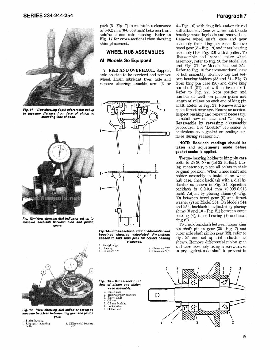
SERIES 234·244·254 Fig. 11- View showing depth micrometer set up to measure distance from face of pinion to mounting face of case. Fig. 12- View showing dial Indicator set up to measure backlash between side and pinion gears. Fig. 13- View showing dial indicator set·up to measure backlash between ring gear and pinion gear. I. Pinion housing 2. Ring gear mounting bolts 3. Differential housing half pack (5-Fig. 7) to maintain a clearance of 0-0.2 mm (0-0.008 inch) between front subframe and axle housing. Refer to Fig. 17 for cross-sectional view showing shim placement. WHEEL HUB ASSEMBLIES All Models So Equipped 7. R&R AND OVERHAUL. Support axle on side to be serviced and remove wheel. Drain lubricant from axle and remove steering knuckle arm (3 or 2 5 4 Fig. 14-Cross·sectional view of differential and housings showing calculated dimensions needed to find shim pack for correct bearing clearance. I. Straightedge 2. Housing 3. Cl earance "A" Fig. 15 - Cross·sectional view of pinion and pinion case assembly. 1. Pinion case 2. Tapered roller bearings 3. Pinion shaft 4. Oil seal 5. Oil seal bushing 6. Lockwasher 7. Slotted nut 4. Cl earance "B" 5. Cl earance "C" o 5 Paragraph 7 4-Fig. 16) with drag link and/or tie rod still attached. Remove wheel hub to axle housing mounting bolts and remove hub. Remove wheel shaft, case and gear assembly from king pin case. Remove bevel gear (3 - Fig. 19) and inner bearing assembly (10-Fig. 20) with a puller. To disassemble and inspect entire wheel assembly, refer to Fig. 20 for Model 234 and Fig. 21 for Models 244 and 254. Refer to Fig. 18 for cross-sectional view of hub assembly. Remove top and bot- tom bearing holders (33 and 21-Fig. 7) from king pin case (26) and drive king pin shaft (31) out with a brass drift. Refer to Fig. 22. Note position and number of teeth on pinion gears and length of splines on each end of king pin shaft. Refer to Fig. 23 . Remove and in- spect thrust bearings. Renew as needed. Inspect bushing and renew if necessary. Install new oil seals and "0" rings. Reassemble by reversing disassembly procedure. Use "Loctite" 515 sealer or equivalent as a gasket on sealing sur- faces during reassembly. NOTE: Backlash readings should be taken and adjustments made before gasket sealer is applied. Torque bearing holder to king pin case bolts to 25-30 N' m (18-22 ft. -lbs.). Dur- ing reassembly, place all shims in their original position. When wheel shaft and holder assembly is installed on wheel hub case, check backlash with a dial in- dicator as shown in Fig. 24. Specified backlash is 0.2-0.4 mm (0.008-0.016 inch). Adjust by placing shims (8-Fig. 20) between bevel gear (9) and thrust washer (7) on Model 234. On Models 244 and 254, backlash is adjusted by placing shims (8 and 10-Fig. 21) between outer bearing (4), inner bearing (7) and snap ring (9). To check backlash between upper king pin shaft pinion gear (35 - Fig. 7) and outer axle shaft pinion gear (28), refer to Fig. 25 and set up dial indicator as shown. Remove differential pinion gear and case assembly using a screwdriver to pry against axle shaft to prevent in 9
This comprehensive shop manual for the International Harvester 244 tractor provides detailed instructions for maintenance and servicing. It includes diagrams and manufacturer specifications to guide you through the repair procedures.
The improved manual features bookmarks, searchable text, an index, and enhanced quality. It is compatible with all versions of Windows, Mac, iOS, BB, Android, etc. The manual is bookmarked and searchable for easy navigation, allowing quick access to service repair procedures.
Topics covered in the manual include brakes, clutch, cooling system, diesel fuel system, differential, electrical system, engine, final drive, four-wheel drive, front system (two-wheel drive), hydraulic system, hydrostatic transmission, power steering gear, PTO, service data, speed transmission, and manual steering gear.
The manual is available in an easy-to-read PDF file format, viewable on any computer. It can be zoomed, printed, and saved for convenience. Technical details and step-by-step instructions are included.
For viewing the manual, it is recommended to use the latest version of Acrobat Reader. For any problems with document display, upgrading to the latest version of Adobe Acrobat Reader is advised.
We offer a wide range of manuals, so feel free to email us about any specific manual you may need.
Recently Viewed
5,521,897Happy Clients
2,594,462eManuals
1,120,453Trusted Sellers
15Years in Business
Price:
Actual Price:
International Harvester 244 Tractor Service Shop Manual - IMPROVED -