Ford TW-5, TW-15, TW-25, TW-35 Tractor Service Repair Manual
What's Included?
Lifetime Access
Fast Download Speeds
Online & Offline Access
Access PDF Contents & Bookmarks
Full Search Facility
Print one or all pages of your manual
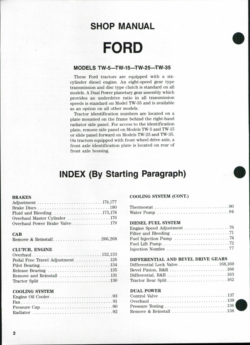
SHOP MANUAL FORD MODELS TW-5—TW-15—TW-25—TW-35 These Ford tractors are equipped with a six- cylinder diesel engine. An eight-speed gear type transmission and disc type clutch is standard on all models. A Dual Power planetary gear assembly which provides an underdrive ratio in all transmission speeds is standard on Model TW-35 and is available as an option on all other models. Tractor identification numbers are located on a plate mounted on the frame behind the right-hand radiator side panel. For access to the identification plate, remove side panel on Models TW-5 and TW45 or slide panel forward on Models TW-25 and TW-35. On tractors equipped with front wheel drive axle, a front axle identification plate is located on rear of front axle housing. INDEX (By Starting Paragraph) BRAKES Adjustment 174,177 Brake Discs 180 Fluid and Bleeding 175,178 Overhaul Master Cylinder 176 Overhaul Power Brake Valve 179 CAB Remove & Reinstall 266,268 CLUTCH, ENGINE Overhaul 132,133 Pedal Free Travel Adjustment 126 Pilot Bearing 134 Release Bearing 135 Remove and Reinstall 131 Tractor Split 130 COOLING SYSTEM Engine Oil Cooler 93 F^n 91 Pressure Cap 90 Radiator 92 COOLING SYSTEM (CONT.) Thermostat 90 Water Pump 94 DIESEL FUEL SYSTEM Engine Speed Adjustment 76 Filter and Bleeding 71 Fuel Ir\jection Pump 74 Fuel Lift Pump 72 Ir\jection Nozzles 77 DIFFERENTIAL AND BEVEL DRIVE GEARS Differential Lock Valve 168,169 Bevel Pinion, R&R 166 Differential, R&R 163 Tractor Rear Split 162 DUAL POWER Control Valve • 137 Overhaul 139 Pressure Testing 136 Remove & Reinstall 138
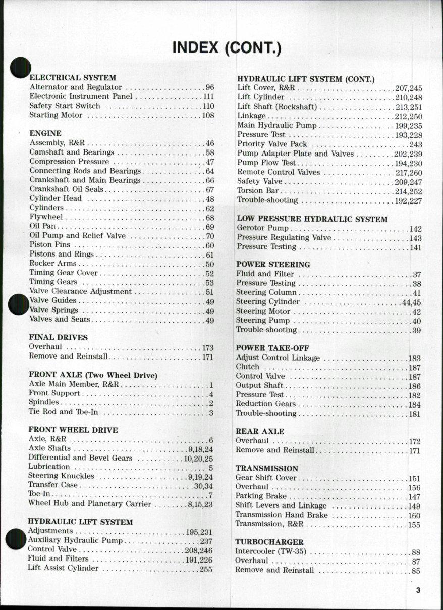
INDEX (CONT.) ELECTRICAL SYSTEM Alternator and Regulator 96 Electronic Instrument Panel Ill Safety Start Switch 110 Starting Motor 108 ENGINE Assembly, R&R 46 Camshaft and Bearings 58 Compression Pressure 47 Connecting Rods and Bearings ! . 64 Crankshaft and Main Bearings 66 Crankshaft Oil Seals 67 Cylinder Head 48 Cylinders 62 Flywheel 68 Oil Pan 69 Oil Pump and Relief Valve 70 Piston Pins 60 Pistons and Rings 61 Rocker Arms 50 Timing Gear Cover 52 Timing Gears 53 Valve Clearance Adjustment 51 Valve Guides 49 Valve Springs 49 Valves and Seats 49 FINAL DRIVES Overhaul I73 Remove and Reinstall 171 FRONT AXLE (Two Wheel Drive) Axle Main Member, R&R 1 Front Support 4 Spindles 2 Tie Rod and Tbe-In 3 FRONT WHEEL DRIVE Axle, R&R 6 Axle Shafts 9,18,24 Differential and Bevel Gears 10,20,25 Lubrication 5 Steering Knuckles 9,19,24 Transfer Case 30,34 Toe-in V. . . . . 7 Wheel Hub and Planetary Carder 8,15,23 HYDRAULIC LIFT SYSTEM Adjustments 195,231 Auxiliary Hydraulic Pump 237 Control Valve 208,246 Fluid and Filters 191,226 Lift Assist Cylinder 255 HYDRAULIC LIFT SYSTEM (CONT,) ' Lift Cover, R&R 207,245 Lift Cylinder 210,248 Lift Shaft (Rockshaft) 213,251 Linkage 212,250 Main Hydraulic Pump 199,235 Pressure Ibst 193,228 Priority Valve Pack 243 Pump Adapter Plate and Valves 202,239 Pump Flow Tbst 194,230 Remote Control Valves 217,260 Safety Valve 209,247 Tbrsion Bar 214,252 Trouble-shooting 192,227 LOW PRESSURE HYDRAULIC SYSTEM Gerotor Pump 142 Pressure Regulating Valve 143 Pressure Testing 141 POWER STEERING Fluid and Filter 37 Pressure Testing 38 Steering Column 41 Steering Cylinder 44,45 Steering Motor 42 Steering Pump 40 Trouble-shooting 39 POWER TAKE-OFF Adjust Control Linkage 183 Clutch 187 Control Valve 187 Output Shaft 186 Pressure Test 182 Reduction Gears 184 Trouble-shooting 181 REAR AXLE Overhaul 172 Remove and Reinstall 171 TRANSMISSION Gear Shift Cover 151 Overhaul 156 Parking Brake 147 Shift Levers and Linkage 149 Transmission Hand Brake 160 Transmission, R&R 155 TURBOCHARGER Intercooler (TW-35) .88 Overhaul 87 Remove and Reinstall 85
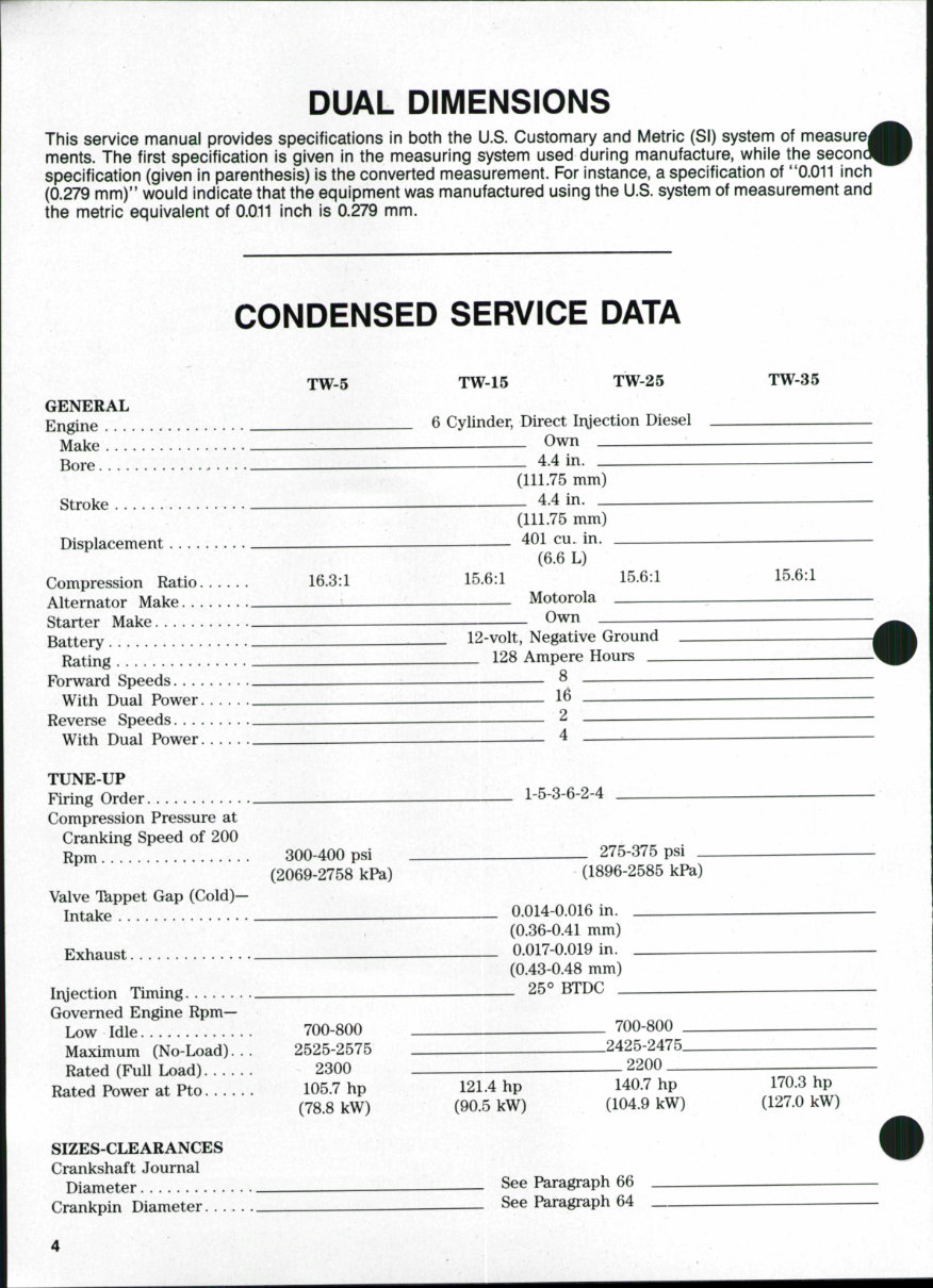
DUAL DIMENSIONS This service manual provides specifications in both the U.S. Customary and Metric (SI) system of ments. The first specification is given in the measuring system used during manufacture, while the specification (given in parenthesis) is the converted measurement. For instance, a specification of **0.011 inch (0.279 mm)" would indicate that the equipment was manufactured using the U.S. system of measurement and the metric equivalent of 0.011 inch is 0.279 mm. . CONDENSED SERVICE DATA TW-5 TW-15 TW-25 TW-35 GENERAL Engine ^— 6 Cylinder, Direct Ir\jection Diesel Make Own Bore 4,4 in. (111.75 mm) Stroke 4.4 in. (111.75 mm) Displacement 401 cu. in. (6.6 L) Compression Ratio ...... 16.3:1 15.6:1 15.6:1 15.6:1 Alternator Make ^ Motorola _ Starter Make Battery .^—^— 12-volt, Negative Ground Rating 128 Ampere Hours Forward Speeds ^ ^ With Dual Power ^ 1^ Reverse Speeds ^ — 2 With Dual Power ^ 4 TUNE-UP Firing Order — 1-5-3-6-2-4 Compression Pressure at Cranking Speed of 200 Rpm 300-400 psi 275-375 psi _ (2069-2758 kPa) (1896-2585 kPa) Valve Tkppet Gap (Cold)— Intake ^ 0.014-0.016 in. (0.36-0.41 mm) Exhaust ^ 0.017-0.019 in. (0.43-0.48 mm) Ir\jection Timing 25° BTDC Governed Engine Rpm— Low Idle 700-800 - 700-800 Maximum (No-Load)... 2525-2575 • 2425-2475 Rated (Full Load) 2300 2200 Rated Power at Pto 105.7 hp 121.4 hp 140.7 hp (78.8 kW) (90.5 kW) (104.9 kW) SIZES-CLEARANCES Crankshaft Journal Diameter See Paragraph 66 Crankpin Diameter See Paragraph 64
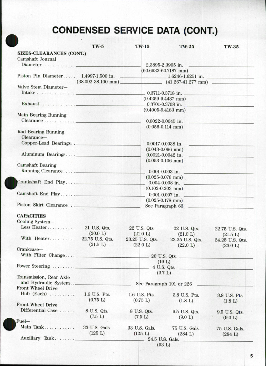
CONDENSED SERVICE DATA (CONT.) TW-5 SIZES-CLEARANCES (CONT.) Camshaft Journal Diameter Piston Pin Diameter 1.4997-1.500 in. (38.092-38.100 mm). Valve Stem Diameter- Intake Exhaust Main Bearing Running Clearance TW-15 TW-25 TW-35 _ 2.3895-2.3905 in. (60.6933-60.7187 mm) . 1.6246-1.6251 in. _ (41.267-41.277 mm) Rod Bearing Running Clearance— Copper-Lead Bearings. Aluminum Bearings. . . Camshaft Bearing Running Clearance .... Irankshaft End Play . Camshaft End Play Piston Skirt Clearance. . .. CAPACITIES Cooling System- Less Heater With Heater. 21 U.S. Qts. (20.0 L) 22.75 U.S. Qts. (21.5 L) Crankcase— With Filter Change Power Steering Transmission, Rear Axle and Hydraulic System. . Front Wheel Drive Hub (Each) 1.6 U.S. Pts. (0.75 L) Front Wheel Drive Differential Case 8 U.S. Qts. (7.5 L) Fuel- Main Tknk 33 U.S. Gals. (125 L) Auxiliary Tknk _ 0.3711-0.3718 in. _ (9.4259-9.4437 mm) _ 0.3701-0.3708 in. _ (9.4005-9.4183 mm) 0.0022-0.0045 in. (0.056-0.114 mm) 0.0017-0.0038 in. (0.043-0.096 mm) 0.0021-0.0042 in. (0.053-0.106 mm) _ 0.001-0.003 in. . (0.025-0.076 mm) . 0.004-0.008 in. fO. 102-0.203 mm") _ 0.001-0.007 in. (0.025-0.178 mm) See Paragraph 63 22 U.S. Qts. (21.0 L) 23.25 U.S. Qts. (22.0 L) 22 U.S. Qts. (21.0 L) 23.25 U.S. Qts. (22.0 L) 22.75 U.S. Qts. (21.5 L) 24.25 U.S. Qts. (23.0 L) 20 U.S. Qts. (19 L) 4 U.S. Qts. (3.7 L) See Paragraph 191 or 226 1.6 U.S. Pts. (0.75 L) 8 U.S. Qts. (7.5 L) 3.8 U.S. Pts. (1.8 L) 9.5 U.S. Qts. (9.0 L) 33 U.S. Gals. 75 U.S. Gals. (125 L) (284 L) 24.5 U.S. Gals. I (93 L) 3.8 U.S. Pts. (1.8 L) 9.5 U.S. Qts. (9.0 L) 75 U.S. Gals. (284 L)
Paragraphs 1-2 FORD FRONT AXLE (TWO WHEEL DRIVE) All Models So Equipped An adjustable tread width front axle (Fig. 1) is stan- dard on all models. On some tractors, the center member (12) is reversed to provide a shorter wheelbase. 1, R&R FRONT AXLE ASSEMBLY. Tb remove front axle, first remove front weights (all models) and carrier (TW-5 and TW-15). Raise front of tractor and support with safety stands. Remove front wheels. Disconnect hydraulic hoses from steering cylinder and plug all openings. Support axle assembly, then remove front pivot support bracket (10—Fig. 1). With- draw axle assembly from front support housing. Tb reinstall axle, reverse the removal procedure. Be sure that a thrust washer (11) is placed on each piv- ot pin. Tighten pivot support bracket cap screws to 200 ft.-lbs. (271 N-m) torque. 2. FRONT WHEEL SPINDLE. Tb remove spindle (1—Fig. 1), raise and support front of tractor. Remove wheel and tire. Remove nut retaining steering arm (8 or 13) to spindle. Note that threads of spindle are staked at the nut to prevent the nut from loosening and it may be difficult to remove. Remove steering arm and withdraw spindle from axle. 1b remove front wheel hub (6—Fig. 2) and bearings, remove hub cap (1) and retaining nut (2). Withdraw hub, bearings, seal (9) and dirt shield (10) if necessary. Clean all parts and inspect for wear or damage. To renew spindle bushings (4 and 6—Fig. 1), drive old bushings out of axle extension and install new bush- ings using a suitable piloted bushing driver Bushings 17 19 Fig. I^Expfoded view of adjustabie front axie assembiy. The center member (12) may be reversed to provide a shorter wheeibase on some modeis. 1. Spindle 2. Spacer 3. Thrust bearing 4. Bushing 5. Axle extension 6. Bushing 7. Seal 8. Steering arm 9. Bushing 10. Pivot support 11. Thrust washer 12. Axle center member 13. Steering arm 14. Ball joint ends 15. Steering cylinder 16. 17. 18. Cylinder anchor bracket Tie rod Tube 19. Tie rod end 6
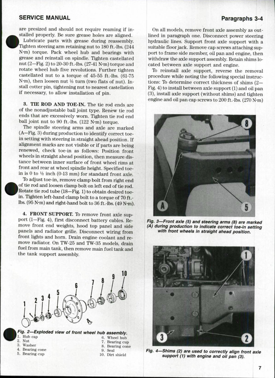
SERVICE MANUAL are presized and should not require reaming if in- stalled properly. Be sure grease holes are aligned. Lubricate parts with grease during reassembly. Tighten steering arm retaining nut to 180 ft.-lbs. (244 N-m) torque. Pack wheel hub and bearings with grease and reinstall on spindle. Tighten castellated nut (2-Fig. 2) to 20-30 ft.-lbs. (27-41 N-m) torque and rotate wheel hub five revolutions. Further tighten castellated nut to a torque of 45-55 ft.-lbs. (61-75 N-m), then loosen nut % turn (two flats of nut). In- stall cotter pin, tightening nut to nearest castellation if necessary, to allow installation of pin. 3. TIE ROD AND TOE-IN. The tie rod ends are of the nonadjustable ball joint type. Renew tie rod ends that are excessively worn. Tighten tie rod end ball joint nut to 90 ft.-lbs. (122 N-m) torque. The spindle steering arms and axle are marked (A—Fig. 3) during production to identify correct toe- in setting with steering in straight ahead position. If alignment marks are not visible or if parts are being renewed, check toe-in as follows: Position front wheels in straight ahead position, then measure dis- tance between inner surface of front wheel rims at front and rear at wheel spindle height. Specified toe- in is 0 to 1/2 inch (0-13 mm) for standard front axle. To adjust toe-in, remove clamp bolt from right end of tie rod and loosen clamp bolt on left end of tie rod. Rotate tie rod tube (18—Fig. 1) to obtain desired toe- in. Tighten left-hand clamp bolt to a torque of 70 ft.- lbs. (95 N-m) and right-hand bolt to 36 ft.-lbs. (49 N-m). 4. FRONT SUPPORT. To remove front axle sup- port (1—Fig. 4), first disconnect battery cables. Re- move front end weights, hood top panel and side panels and radiator grille. Disconnect wiring from front lights and horn. Drain engine coolant and re- move radiator. On TW-25 and TW-35 models, drain fuel from main tank, then remove main fuel tank and the tank support assembly. Fig. 2—Exploded view of front wheei hub assembiy. 1. Hub cap 6. Wheel hub ^- Nut 7, Bearing cup 3. Washer 8. Bearing cone 4. Bearing cone 9. Seal 5. Bearing cup 10. Dirt shield Paragraphs 3-4 On all models, remove front axle assembly as out- lined in paragraph one. Disconnect power steering hydraulic lines. Support front axle support with a suitable floor jack. Remove cap screws attaching sup- port to frame side member, oil pan and engine, then withdraw the axle support assembly. Retain shims lo- cated between axle support and engine. To reinstall axle support, reverse the removal procedure while noting the following special instruc- tions: To determine correct thickness of shims (2— Fig. 4) to install between axle support (1) and oil pan (3), install axle support (without shims) and tighten engine and oil pan cap screws to 200 ft.-lbs. (270 N-m) 5 Fig. 3^Front axle (5) and steering arms (8) are marked (A) during production to indicate correct toe-in setting with front wheels in straight ahead position. Fig. 4Shims (2) are used to correctiy aiign front axie support (1) with engine and oii pan (3).
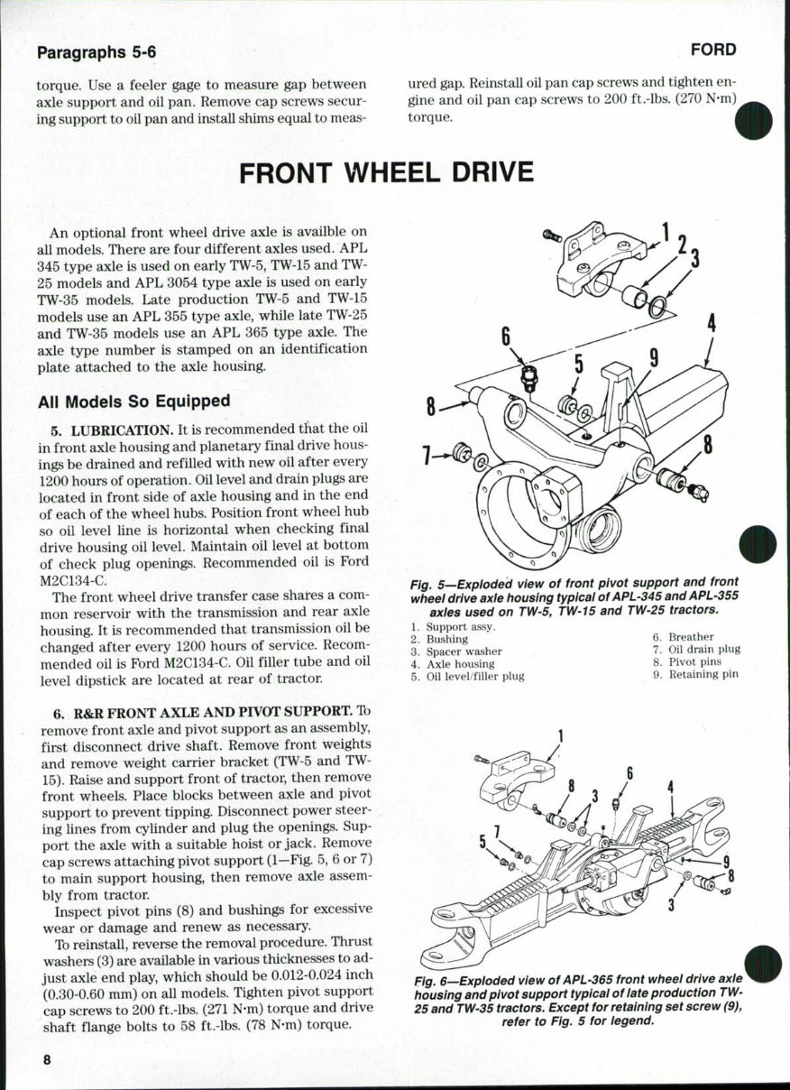
Paragraphs 5-6 FORD torque. Use a feeler gage to measure gap between axle support and oil pan. Remove cap screws secur- ing support to oil pan and install shims equal to meas- ured gap. Reinstall oil pan cap screws and tighten en- gine and oil pan cap screws to 200 ft.-lbs, (270 N-m) torque. FRONT WHEEL DRIVE An optional front wheel drive axle is availble on all models. There are four different axles used, APL 345 type axle is used on early TW-5, TW-15 and TW- 25 models and APL 3054 type axle is used on early TW-35 models. Late production TW-5 and TW-15 models use an APL 355 type axle, while late TW-25 and TW-35 models use an APL 365 type axle. The axle type number is stamped on an identification plate attached to the axle housing. All Models So Equipped 5. LUBRICATION. It is recommended that the oil in front axle housing and planetary final drive hous- ings be drained and refilled with new oil after every 1200 hours of operation. Oil level and drain plugs are located in front side of axle housing and in the end of each of the wheel hubs. Position front wheel hub so oil level line is horizontal when checking final drive housing oil level. Maintain oil level at bottom of check plug openings. Recommended oil is Ford M2C134-C. The front wheel drive transfer case shares a com- mon reservoir with the transmission and rear axle housing. It is recommended that transmission oil be changed after every 1200 hours of service. Recom- mended oil is Ford M2C134-C, Oil filler tube and oil level dipstick are located at rear of tractor. 6. R&R FRONT AXLE AND PIVOT SUPPORT. Tb remove front axle and pivot support as an assembly, first disconnect drive shaft. Remove front weights and remove weight carrier bracket (TW-5 and TW- 15). Raise and support front of tractor, then remove front wheels. Place blocks between axle and pivot support to prevent tipping. Disconnect power steer- ing lines from cylinder and plug the openings. Sup- port the axle with a suitable hoist or jack. Remove cap screws attaching pivot support (1—Fig. 5, 6 or 7) to main support housing, then remove axle assem- bly from tractor. Inspect pivot pins (8) and bushings for excessive wear or damage and renew as necessary. Tb reinstall, reverse the removal procedure. Thrust washers (3) are available in various thicknesses to ad- just axle end play, which should be 0.012-0.024 inch (0.30-0.60 mm) on all models. Tighten pivot support cap screws to 200 ft.-lbs. (271 N-m) torque and drive shaft flange bolts to 58 ft.-lbs. (78 N-m) torque. 2 Fig, 5—Exploded view of front pivot support and front wheel drive axie housing typical ofAPL-345 andAPL-355 axies used on TW'5, TW-15 and TW'25 tractors. Support assy. Bushing 6. Breather Spacer washer , 7. Oil drain plug Axle housing 8. Pivot pins 1 2 3 4 5. Oil level/filler plug 9. Retaining pin Fig. e-^Exploded view ofAPL-365 front wheei drive axie housing and pivot support typicai of late production TW- 25 and TW'35 tractors. Except for retaining set screw (9), refer to Fig, 5 for iegend. 8
Paragraphs 5-6 FORD torque. Use a feeler gage to measure gap between axle support and oil pan. Remove cap screws secur- ing support to oil pan and install shims equal to meas- ured gap. Reinstall oil pan cap screws and tighten en- gine and oil pan cap screws to 200 ft.-lbs, (270 N-m) torque. FRONT WHEEL DRIVE An optional front wheel drive axle is availble on all models. There are four different axles used, APL 345 type axle is used on early TW-5, TW-15 and TW- 25 models and APL 3054 type axle is used on early TW-35 models. Late production TW-5 and TW-15 models use an APL 355 type axle, while late TW-25 and TW-35 models use an APL 365 type axle. The axle type number is stamped on an identification plate attached to the axle housing. All Models So Equipped 5. LUBRICATION. It is recommended that the oil in front axle housing and planetary final drive hous- ings be drained and refilled with new oil after every 1200 hours of operation. Oil level and drain plugs are located in front side of axle housing and in the end of each of the wheel hubs. Position front wheel hub so oil level line is horizontal when checking final drive housing oil level. Maintain oil level at bottom of check plug openings. Recommended oil is Ford M2C134-C. The front wheel drive transfer case shares a com- mon reservoir with the transmission and rear axle housing. It is recommended that transmission oil be changed after every 1200 hours of service. Recom- mended oil is Ford M2C134-C, Oil filler tube and oil level dipstick are located at rear of tractor. 6. R&R FRONT AXLE AND PIVOT SUPPORT. Tb remove front axle and pivot support as an assembly, first disconnect drive shaft. Remove front weights and remove weight carrier bracket (TW-5 and TW- 15). Raise and support front of tractor, then remove front wheels. Place blocks between axle and pivot support to prevent tipping. Disconnect power steer- ing lines from cylinder and plug the openings. Sup- port the axle with a suitable hoist or jack. Remove cap screws attaching pivot support (1—Fig. 5, 6 or 7) to main support housing, then remove axle assem- bly from tractor. Inspect pivot pins (8) and bushings for excessive wear or damage and renew as necessary. Tb reinstall, reverse the removal procedure. Thrust washers (3) are available in various thicknesses to ad- just axle end play, which should be 0.012-0.024 inch (0.30-0.60 mm) on all models. Tighten pivot support cap screws to 200 ft.-lbs. (271 N-m) torque and drive shaft flange bolts to 58 ft.-lbs. (78 N-m) torque. 2 Fig, 5—Exploded view of front pivot support and front wheel drive axie housing typical ofAPL-345 andAPL-355 axies used on TW'5, TW-15 and TW'25 tractors. Support assy. Bushing 6. Breather Spacer washer , 7. Oil drain plug Axle housing 8. Pivot pins 1 2 3 4 5. Oil level/filler plug 9. Retaining pin Fig. e-^Exploded view ofAPL-365 front wheei drive axie housing and pivot support typicai of late production TW- 25 and TW'35 tractors. Except for retaining set screw (9), refer to Fig, 5 for iegend. 8
SERVICE MANUAL 7. TOE-IN. Front wheel toe-in should be 0-1/4 inch (0-6 mm) on all models. To adjust toe-in, disconnect itie rod ball joint ends. Loosen clamp bolt, then turn tie rod end until desired toe-in is obtained when ball joints are reconnected. Be sure tie rods are adjusted equally. APL-345 AND APL-355 TYPE AXLES All Models So Equipped 8. WHEEL HUB AND PLANETARY CARRIER. Ib remove wheel hub and planetary assembly from either side, first raise and support front axle and re- move wheel and tire. Remove drain plug (3—Fig. 10) and drain oil from hub. Remove the two socket-head retaining screws (1—Fig. 10), then insert pry bars into slots (2) in hub and pry planetary carrier (35) away from hub. On APL-345 axles, remove cap screws (30—Fig. 8) attaching ring gear (29) to steering knuckle (17). Pull the ring gear off the knuckle locating dowels (18) us- ing a suitable puller. Pull the hub (24) and bearings off steering knuckle. NOTE: The center screw of puller must not apply force to end of sun gear shaft (36). Thread three long cap screws into ring gear boit hoies and iocate a step piate on heads of cap screws to provide a base for pulier screw. On APL-355 axles, remove locking plate (30—Fig. 9) securing slotted nut (28). Remove the slotted nut using special hub nut socket (Nuday tool number 12235) or other suitable tool. Remove ring gear (29), hub (24) and bearings from steering knuckle (17). On all models, remove bearings and oil seal from hub. Remove retaining rings (32-Fig. 8 or 9) and withdraw planetary gears (31) and bearings (33) from carrier. Remove thrust washer (40). The sun gear (36) is attached to axle shaft universal joint (11) by a re- taining ring (16). Tb remove the retaining ring and sun gear, the steering knuckle (17) must first be removed as outlined in paragraph 9. Inspect all parts for wear or damage and renew as necessary. Ib reassemble, heat the inner and outer bearing cones (22 and 27-Fig. 8 or 9) to 212° F (100° C). Po- sition inner bearing cone in hub, then install a new oil seal (21) to hold bearing in place. On APL-355 axle, install scraper '*V'' ring (20) onto the oil seal with the " V side facing outward. On all axles, coat oil seal lip with grease and install hub assembly onto steering knuckle while bearing cone is still hot. As- semble the heated outer bearing cone onto the knuckle and hub. On APL-345 axle, install ring gear onto spindle and tighten retaining cap screws evenly to 65 ft.-lbs. (90 N-m) torque. Paragraphs 7-8 On APL-355 axle, install ring gear and slotted nut onto steering knuckle and adjust bearing preload as follows: With hub nut finger tight (no preload on bearings), wrap a cord around hub stud nuts as shown in Fig. 11 and use a spring scale to measure rolling resistance of hub. Note spring scale reading while slowly rotating the hub, then tighten hub nut in small increments until hub rolling resistance in- creases 5-12 pounds (2.3-5.4 Kg) above spring scale reading obtained with zero bearing preload. Install locking plate (30—Fig. 9) into one of the slots in nut to lock it in place. Install planetary gears with bearings in carrier and secure with retaining rings. Be sure gears are posi- tioned so side with chamfered bore is facing carrier housing. On all axles, the thrust washer (40—Fig. 8 or 9) lo- cated in center of planetary carrier controls axle shaft end play. The thrust washer is available in var- ious thicknesses. Tb determine correct thickness of washer to provide specified axle shaft end play of 0.012-0.024 inch (0.30-0.60 mm), proceed as follows: Place original thrust washer in carrier, then use a straightedge and depth micrometer to measure dis- tance (A—Fig. 12) from mounting surface of carrier to face of thrust washer. Push sun gear inward, then measure distance (B) from end of sun gear shaft to mounting surface of hub. Subtract dimension (B) Fig. 7^Expioded view ofAPL'3054 front wheei drive axie housing and pivot support used on eariy TW'35 tractors. 3. Spacer washers 4. Axle housing 7. Oil drain plug 5. Oil level/filler 8. Pivot pins plug 9. Retaining pins 6. Breather 10. Pivot bracket 9
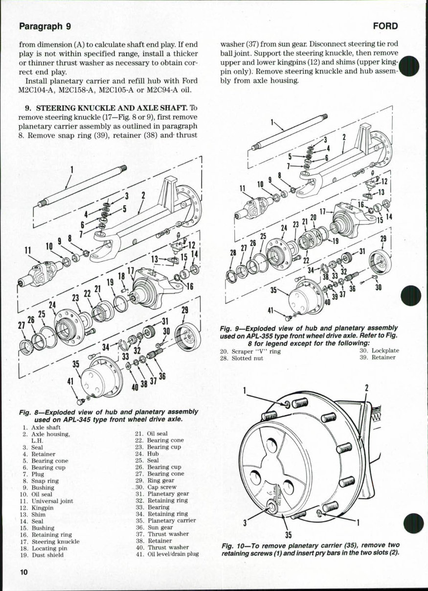
Paragraph 9 FORD from dimension (A) to calculate shaft end play. If end play is not within specified range, install a thicker or thinner thrust washer as necessary to obtain cor- rect end play. Install planetary carrier and refill hub with Ford M2C104-A, M2C158-A, M2C105-A or M2C94-A oil. washer (37) from sun gear. Disconnect steering tie rod ball joint. Support the steering knuckle, then remove upper and lower kingpins (12) and shims (upper king- pin only). Remove steering knuckle and hub assem- bly from axle housing. 9. STEERING KNUCKLE AND AXLE SHAFT. To remove steering knuckle (17—Fig. 8 or 9), first remove planetary carrier assembly as outlined in paragraph 8. Remove snap ring (39), retainer (38) and- thrust Fig. B—Exploded view of hub and pianetary assembiy used on APL-345 type front wheel drive axie. 1. Axle shaft 2. Axle housing, 21. Oil seal 22. Bearing cone 23. Bearing cup 24. Hub 25. Seal 26. Bearing cup 27. Bearing cone 29. Ring gear *30. Cap screw . 31. Planetary gear 32. Retaining ring 33. Bearing - 34. Retaining ring 35. Planetary carrier ' 36. Sun gear 37. Thrust washer 38. Retainer 40. Thrust washer Axle housing, L.H. Seal Retainer Bearing cone Bearing cup Plug Snap ring . . Bushing Oil seal Universal joint Kingpin Shim Seal Bushing Retaining ring 17. Steering knuckle 18. Locating pin 19. Dust shield 3. 4. 5. 6. 7. 8. 9. 10. 11. 12. 13. 14. 15. 16. Fig. 9—Exploded view of hub and planetary assembly used on APL'355 type front wheel drive axie. Refer to Fig, 8 for iegend except for the following: 20. Scraper "V" ring 30. Lockplate 28. Slotted nut 39. Retainer 3 41. Oil level/drain plug Fig. 10—To remove pianetary carrier (35), remove two retaining screws (1) and insert pry bars in the two slots (2). 10
Ford TW-5, TW-15, TW-25, TW-35 Tractor Service Repair Manual is a comprehensive electronic guide providing essential information for vehicle maintenance and repair. It is a valuable resource for both professional mechanics and DIY enthusiasts.
This manual covers a wide range of topics including brakes, cab, clutch, engine, cooling system, diesel fuel system, differential & bevel drive gears, dual power, electrical system, final drives, front axle, front wheel drive, hydraulic system, hydraulic lift system, low-pressure hydraulic system, power steering, power take-off, rear axle, transmission, turbocharger, and more.
The manual is 100% complete and intact, with no missing or corrupt pages/sections. It offers comprehensive explanations of installation, removal, disassembly, assembly, repair, and check procedures in a clear and sequential order.
Models Covered:
Ford Tractor TW-5
Ford Tractor TW-15
Ford Tractor TW-25
Ford Tractor TW-35
File Format: PDF
Compatibility: All Versions of Windows & Mac
Language: English
Requirements: Adobe Reader & WinZip
Whether you are a professional mechanic or a DIY enthusiast, this manual in PDF format is an invaluable and cost-effective tool for maintaining and repairing your vehicle.
Recently Viewed
5,521,897Happy Clients
2,594,462eManuals
1,120,453Trusted Sellers
15Years in Business
Price:
Actual Price:
Ford TW-5, TW-15, TW-25, TW-35 Tractor Service Repair Manual