INDEX (By Starting Paragraph) Models 9N-2N 8N BELT PULLEY 142 142 BRAKES Adjustment 135 136 Brake Shoes 137 138 CLUTCH Adjustment 97 98 Overhaul 101 101 Tractor Split 99 100 Troubleshooting 96 96 COOLING SYSTEM Radiator 59 59 Thermostat 63 63 Water Pump 60 60 DIFFERENTL\L, BEVEL GEARS AND REAR AXLES Axles and Bearings 129 132 Differential 124 124 Main Drive Bevel Gears 127 127 Tractor Rear Split 126 126 ELECTRICAL AND IGNITION SYSTEM Battery Ignition 85 85, 88 Charging System 64 64 Generator and Regulator 65 65 Generator Overhaul. 73 73 Ignition System 84 84 Magneto Ignition System (2N) . 92 Starting Motor and Switch .... 81 81 FRONT AXLE Axle Center Member and King Pin 12 12 Axle Front Support 13 13 Front Wheel Bearings 10 10 Spindle Bushings 11 H Tread Width and Toe-In 9 9 FUEL SYSTEM Carburetor Operation 48 48 Carburetor Overhaul 52 52 Troubleshooting 51 51 ENGINE Assembly, R&R 21 21 Compression Pressure 22 22 Connecting Rod and Piston Units 33 33 Models 9N-2N 8N Connecting Rods and Bearings . 39 Camshaft 32 Crankshaft and Main Bearings. 40 Crankshaft Oil Seals 43 Cyhnder Head 23 Flywheel 44 Oil Pan 45 Oil Pump 46 Piston Pins 35 Piston Rings 34 Sleeves and Pistons 36 Timing Gears and Cover 29 Valves 24, 25 Valve Guides and Springs ..... 27 Valve PusTi Rods. . 28 Valve Seats 26 GOVERNOR Adjustment 57 R&R and Overhaul 58 Troubleshooting 56 HYDRAULIC SYSTEM Adjustments 149 Hydraulic Lift Operation 143 Hydraulic Pump R&R and Test. 160 Lift Cover 156 Pump Overhaul 169 Troubleshooting 155 LUBRICATION AND MAINTENANCE Lubrication 2 2 Maintenance Procedures 4 4 Scheduled Maintenance 1 1 39 32 40 43 23 44 45 46 35 34 36 29 24,25 27 28 26 57 58 56 151 143 160 158 162 155 PART NUMBERS 175 175 POWER TAKE-OFF Pto Shifter Unit 141 141 Output Shaft 139, 140 140 SHERMAN TRANSMISSION Overhaul 105 105 Remove and Reinstall 103 103 STANDARD TRANSMISSION Overhaul HO 117 Remove and Reinstall 109 109 STEERING SYSTEM Steering Gear Adjustment 14 16,18 Steering Gear R&R and Overhaul 15 17, 19
DUAL DIMENSIONS This service manual provides specifications in both U.S. Customary and Metric (SI) systems of measurement. The first specification is given in the measuring system perceived by us to be the preferred system when servicing a particular component, whiie the second specification (given in parenthesis) is the converted measurement. For instance, a specification of 0.011 inch (0.28 mm) wouid indicate that we feel the preferred measurement in this instance is the U.S. Customary system of measurement and the Metric equivalent of 0.011 inch is 0.28 mm. CONDENSED SERVICE DATA Models 9N,2N,8N GENERAL Engine Make Own Engine Type L-Head Number of Cylinders 4 Bore 3.187 in. (80.96 mm) Stroke 3.750 in. (95.25 mm) Displacement 119.7 cu. in. (1.9 L) Power Rating at Belt Pulley—Maximum 9N, 2N 23.6 hp (17.6 kW) 8N 27.3 hp (20.4 kW) Power Rating at Drawbar—Maximum 9N, 2N 16.3 hp (12.2 kW) 8N 23.2 hp (17.3 kW) Compression Ratio—Gasoline: 9N, 2N, Early 8N 6:1 Later 8N 6.5:1 Pistons Removed From Above Main Bearings, Number of 3 Main Bearings, Adjustable? No . Rod Bearings, Adjustable? No Cylinder Sleeves, Dry, Wet? Dry Production Cylinder Sleeves- Material (8N Prior to S.N. 433578, 9N,2N) Steel Material (8N After S.N. 433577) Cast Iron Service Cylinder Sleeves- Material (All Models) Cast Iron Generator Make Own Maximum Output 20 Amps Starter Make Own Type 6-Volt Battery ^ Type 6-Volt Ground Terminal . Positive Models . 9N,2N,8N Tire Size^—Standard Front 4-19 4-ply Rear: 9N (Early) 8-32 4-ply 9N (Late)-2N-8N 10-28 4-ply Transmission Type Constant Mesh Forward Speeds (9N, 2N) 3 Forward Speeds (8N) 4 Hydraulic Pump Type Scotch Yoke Piston Capacity @ 2000 Engine Rpm . . . 2.85 Gal./min. (10.8L/min.) TUNE-UP Firing Order 1-2-4-3 Valve Tappet Gap (Cold) Inlet. 0.010-0.012 in. (0.26-0.30 mm) Exhaust 0.014-0.016 in. (0.36-0.40 mm) Valve Face Angle Inlet and Exhaust 45° Valve Seat Angle Inlet and Exhaust 45° Ignition Distributor Make Own Distributor Model 8N Prior to S.N. 263844, 9N, 2N) 9N12100 8N After S.N. 263843 8N12127 Breaker Point Gap Angle Mounted Distributor No. 8N12127 0.025 in. (0.63 mm) Face Mounted Distributor No. 9N12000 0.015 in. (0.38 mm) Retarded Timing 8N Prior to S.N. 263844, 9N, 2N TDC 8N After S.N. 263843 4° BTDC Advanced Timing 8N Prior to S.N. 263844, 9N, 2N 25° BTDC Advanced Timing 8N After S.N. 263843 ........ .. ! . . . 17° BTDC
DUAL DIMENSIONS This service manual provides specifications in both U.S. Customary and Metric (SI) systems of measurement. The first specification is given in the measuring system perceived by us to be the preferred system when servicing a particular component, whiie the second specification (given in parenthesis) is the converted measurement. For instance, a specification of 0.011 inch (0.28 mm) wouid indicate that we feel the preferred measurement in this instance is the U.S. Customary system of measurement and the Metric equivalent of 0.011 inch is 0.28 mm. CONDENSED SERVICE DATA Models 9N,2N,8N GENERAL Engine Make Own Engine Type L-Head Number of Cylinders 4 Bore 3.187 in. (80.96 mm) Stroke 3.750 in. (95.25 mm) Displacement 119.7 cu. in. (1.9 L) Power Rating at Belt Pulley—Maximum 9N, 2N 23.6 hp (17.6 kW) 8N 27.3 hp (20.4 kW) Power Rating at Drawbar—Maximum 9N, 2N 16.3 hp (12.2 kW) 8N 23.2 hp (17.3 kW) Compression Ratio—Gasoline: 9N, 2N, Early 8N 6:1 Later 8N 6.5:1 Pistons Removed From Above Main Bearings, Number of 3 Main Bearings, Adjustable? No . Rod Bearings, Adjustable? No Cylinder Sleeves, Dry, Wet? Dry Production Cylinder Sleeves- Material (8N Prior to S.N. 433578, 9N,2N) Steel Material (8N After S.N. 433577) Cast Iron Service Cylinder Sleeves- Material (All Models) Cast Iron Generator Make Own Maximum Output 20 Amps Starter Make Own Type 6-Volt Battery ^ Type 6-Volt Ground Terminal . Positive Models . 9N,2N,8N Tire Size^—Standard Front 4-19 4-ply Rear: 9N (Early) 8-32 4-ply 9N (Late)-2N-8N 10-28 4-ply Transmission Type Constant Mesh Forward Speeds (9N, 2N) 3 Forward Speeds (8N) 4 Hydraulic Pump Type Scotch Yoke Piston Capacity @ 2000 Engine Rpm . . . 2.85 Gal./min. (10.8L/min.) TUNE-UP Firing Order 1-2-4-3 Valve Tappet Gap (Cold) Inlet. 0.010-0.012 in. (0.26-0.30 mm) Exhaust 0.014-0.016 in. (0.36-0.40 mm) Valve Face Angle Inlet and Exhaust 45° Valve Seat Angle Inlet and Exhaust 45° Ignition Distributor Make Own Distributor Model 8N Prior to S.N. 263844, 9N, 2N) 9N12100 8N After S.N. 263843 8N12127 Breaker Point Gap Angle Mounted Distributor No. 8N12127 0.025 in. (0.63 mm) Face Mounted Distributor No. 9N12000 0.015 in. (0.38 mm) Retarded Timing 8N Prior to S.N. 263844, 9N, 2N TDC 8N After S.N. 263843 4° BTDC Advanced Timing 8N Prior to S.N. 263844, 9N, 2N 25° BTDC Advanced Timing 8N After S.N. 263843 ........ .. ! . . . 17° BTDC
V / Models V.:' • : 9N,2N,8N TUNE-UP (Cont.) Flywheel Timing Mark Indicating: Retarded Timing (8N Prior to S.N. 263844, 9N, 2N) None Retarded Timing (8N After S.N. 263843) 4° Line Advanced Timing (8N Prior to S.N. 263844, 9N, 2N) None Advanced Timing (8N After S.N. 263843) 17° Line Distributor Governor Advance Curve. . . See Text Spark Plug Make Champion Plug Model for Gasoline HIO Electrode Gap 0.025-0.028 in. (0.64-0.71 mm) Carburetor Make Marvel-Schebler Carburetor Model See Text Carburetor Float Setting %2 in. (7 mm) Carburetor Initial Adjustment Idle Adjustment Needle 1 Turn Open Main Jet Adjustment Needle 1 Tum Open Engine Low Idle RPM 400 Engine High Idle RPM 2200 Belt Pulley RPM @ 2000 Engine RPM 1358 Pto RPM @ 1500 Engine RPM 545 Compression Pressure @ Cranking Speed Minimum 90 psi (620 kPa) SIZES—CLEARANCES Crankshaft Joumal Diameter 2.248-2.249 in. (57.10-57.12 mm) Crankpin Diameter .' 2.094 in. (53.18 mm) Camshaft Joumal Diameter 1.797 in. (45.64 mm) Piston Pin Diameter 0.7501-0.7504 in. (19.05-19.06 mm) Valve Stem Diameter One-Piece Valve Guide 0.341-0.342 in. (8.66 mm) Models 9N,2N,8N Two-Piece Valve Guide 0.3105-0.3115 in. (7.89-7.91 mm) Cam Follower (Push Rod) Diameter... 0.9995 in. (25.38 mm) Compression Ring Width 0.093 in. (2.36 mm) Oil Ring Width 0.187 in. (4.75 mm) Main Bearings Running Clearance 0.001-0.003 in. (0.025-0.076 mm) Rod Bearings Running Clearance 0.001-0.0035 in. (0.025-0.089 mm) Piston Skirt Clearance Steel Pistons 0.0025-0.004 in. (0.064-0.101 mm) Aluminum Pistons 0.0015-0.0025 in. (0.038-0.063 mm) Camshaft Bearing Clearance 0.001-0.002 in. (0.025-0.050 mm) Cam Follower (Push Rod) Running Clearance 0.0004-0.001 in. (0.010-0.025 mm) Crankshaft End Play 0.002-0.006 in. (0.05-0.15 mm) CAPACITIES Coohng System 3 Gallons (11.3 L) Crankcase Oil (With Filter Change) 6 Quarts (5.6 L) Fuel Tank Standard 9 Gallons (34 L) Reserve 1 Gallon (3.8 L) Transmission, Differential & Hydraulic System 5 Gallons (18.9 L) Belt Pulley Housing V3 Quart (0.3 L) 8
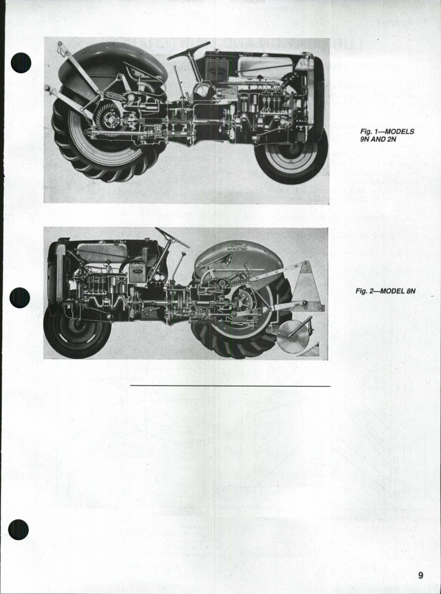
Fig, 1—MODELS 9NAND2N Fig. 2—MODEL 8N
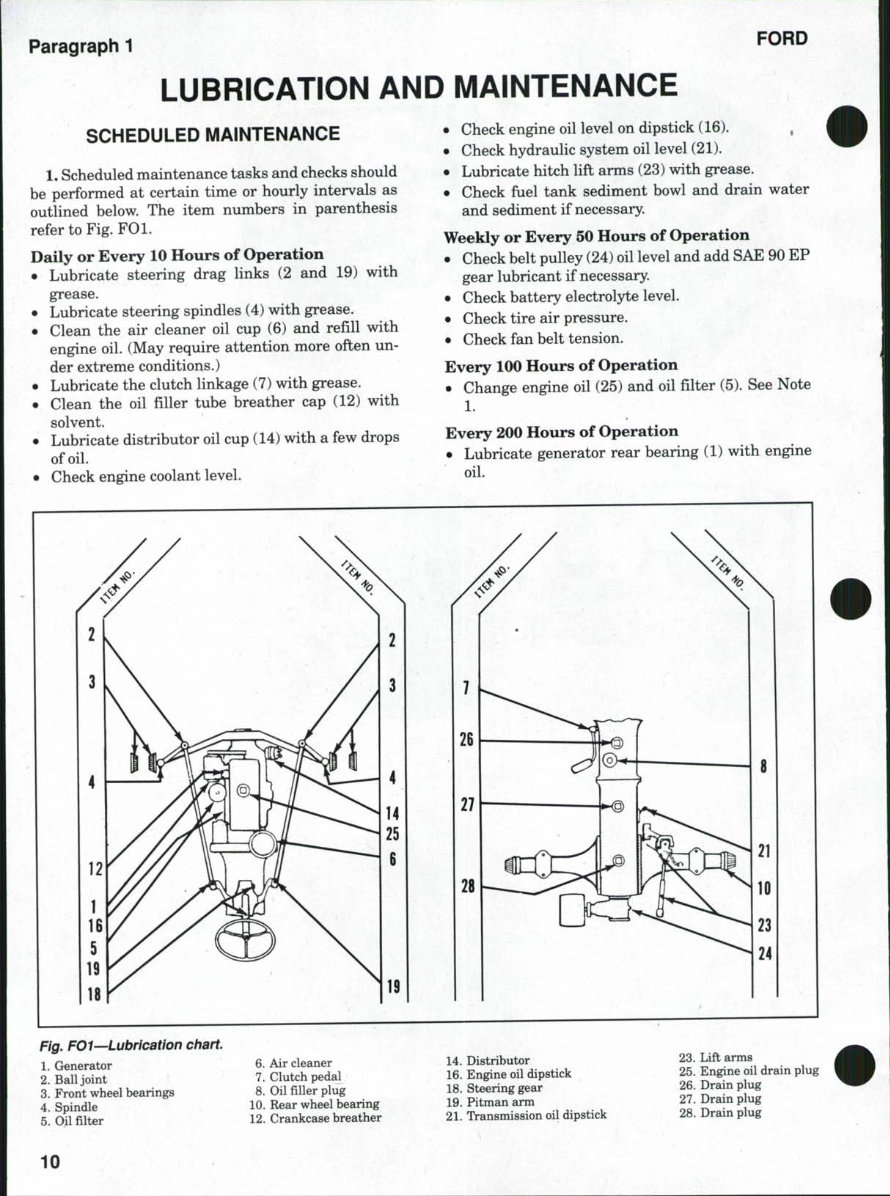
Paragraph 1 FORD LUBRICATION AND MAINTENANCE SCHEDULED MAINTENANCE 1. Scheduled maintenance tasks and checks should be performed at certain time or hourly intervals as outlined below. The item numbers in parenthesis refer to Fig. FOl. Daily or Every 10 Hours of Operation • Lubricate steering drag links (2 and 19) with grease. • Lubricate steering spindles (4) with grease. • Clean the air cleaner oil cup (6) and refill with engine oil. (May require attention more often un- der extreme conditions.) • Lubricate the clutch linkage (7) with grease. • Clean the oil filler tube breather cap (12) with solvent. • Lubricate distributor oil cup (14) with a few drops of oil. • Check engine coolant level. • Check engine oil level on dipstick (16). , • Check hydraulic system oil level (21). • Lubricate hitch lift arms (23) Mdth grease. • Check fuel tank sediment bowl and drain water and sediment if necessary. Weekly or Every 50 Hours of Operation • Check belt pulley (24) oil level and add SAE 90 EP gear lubricant if necessary. • Check battery electrolyte level. • Check tire air pressure. • Check fan belt tension. Every 100 Hours of Operation • Change engine oil (25) and oil filter (5). See Note 1. Every 200 Hours of Operation • Lubricate generator rear bearing (1) with engine oil. Fig. FOl—Lubrication chart. 1. Grenerator 2. Ball joint 3. Front wheel bearings 4. Spindle 5. Oil filter ; 6. Air cleaner 7. Clutch pedal 8. Oil filler plug 10. Rear wheel bearing 12. Crankcase breather 14. Distributor 16. Engine oil dipstick 18. Steering gear 19. Pitman arm 21. Transmission oil dipstick 23. Lift arms 25. Engine oil drain plug 26. Drain plug 27. Drain plug 28. Drain plug 10
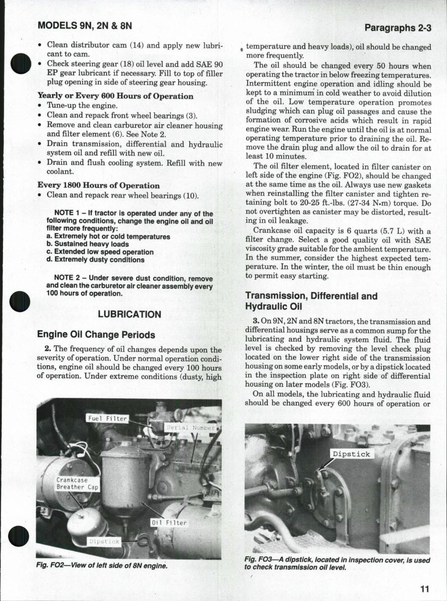
MODELS 9N, 2N & 8N ^^^ h • Clean distributor cam (14) and apply new lubri- cant to cam. • Check steering gear (18) oil level and add SAE 90 EP gear lubricant if necessary. Fill to top of filler plug opening in side of steering gear housing. Yearly or Every 600 Hours of Operation • Tune-up the engine. • Clean and repack front wheel bearings (3). • Remove and clean carburetor air cleaner housing and filter element (6). See Note 2. • Drain transmission, differential and hydraulic system oil and refill with new oil. • Drain and flush cooling system. Refill with new coolant. Every 1800 Hours of Operation • Clean and repack rear wheel bearings (10). NOTE 1 - If tractor is operated under any of the following conditions, change the engine oii and oii fiiter more frequently: a. Extremeiy hot or coid temperatures b. Sustained heavy loads c. Extended low speed operation d. Extremely dusty conditions NOTE 2 - Under severe dust condition, remove and ciean the carburetor air cieaner assembiy every 100 hours of operation. LUBRICATION Engine Oil Change Periods 2. The frequency of oil changes depends upon the severity of operation. Under normal operation condi- tions, engine oil should be changed every 100 hours of operation. Under extreme conditions (dusty, high Paragraphs 2-3 ^ temperature and heavy loads), oil should be changed more frequently. The oil should be changed every 50 hours when operating the tractor in below freezing temperatures. Intermittent engine operation and idling should be kept to a minimum' in cold weather to avoid dilution of the oil. Low temperature operation promotes sludging which can plug oil passages and cause the formation of corrosive acids which result in rapid engine wear. Run the engine until the oil is at normal operating temperature prior to draining the oil. Re- move the drain plug and allow the oil to drain for at least 10 minutes. The oil filter element, located in filter canister on left side of the engine (Fig. F02), should be changed at the same time as the oil. Always use new gaskets when reinstalling the filter canister and tighten re- taining bolt to 20-25 ft.-lbs. (27-34 N.m) torque. Do not overtighten as canister may be distorted, result- ing in oil leakage. Crankcase oil capacity is 6 quarts (5.7 L) with a filter change. Select a good quality oil with SAE viscosity grade suitable for the ambient temperature. In the summer, consider the highest expected tem- perature. In the winter, the oil must be thin enough to permit easy starting. Transmission, Differentiai and Hydraulic Oii 3. On 9N, 2N and 8N tractors, the transmission and differential housings serve as a common sump for the lubricating and hydraulic system fiuid. The fiuid level is checked by removing the level check plug located on the lower right side of the transmission housing on some early models, or by a dipstick located in the inspection plate on right side of differential housing on later models (Fig. F03). On all models, the lubricating and hydraulic fiuid should be changed every 600 hours of operation or Fig. FO2—View of ieft side of 8N engine. Fig. FO3—A dipstick, iocated in inspection cover, is used to checii transmission oii ievei. 11
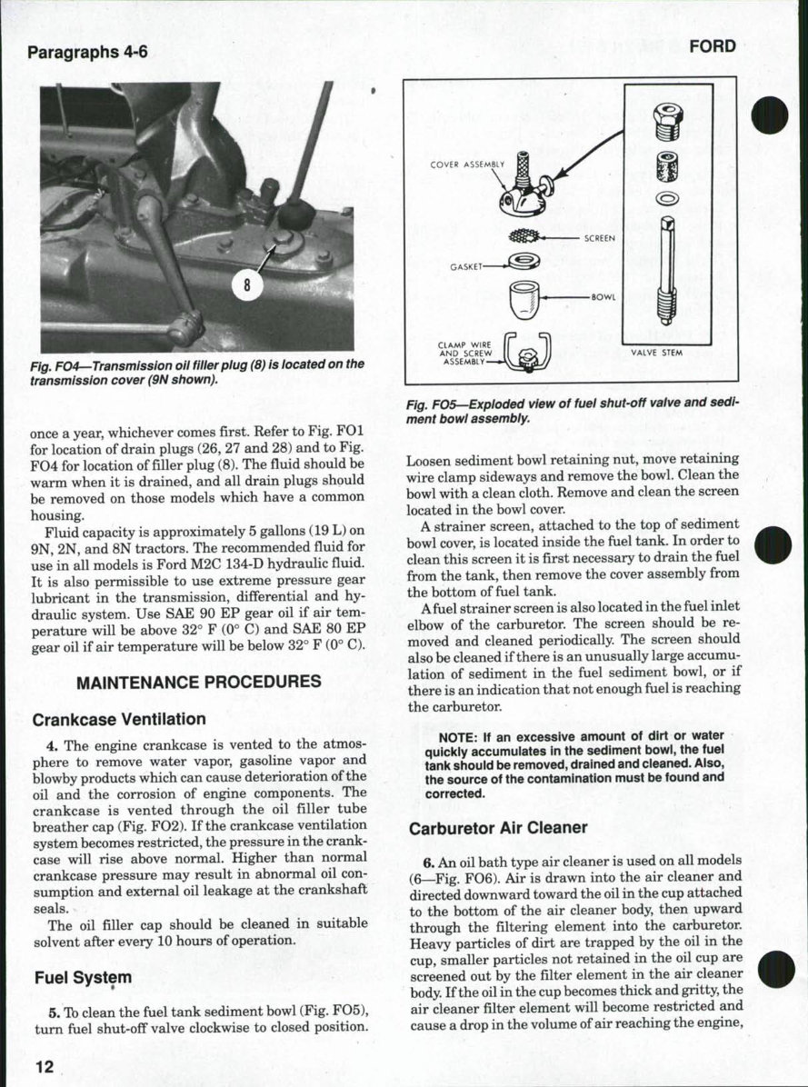
Paragraphs 4-6 FORD Fig. F04—Transmission oil filler piug (8) is located on the transmission cover (9N shown). once a year, whichever comes first. Refer to Fig. FOl for location of drain plugs (26, 27 and 28) and to Fig. F04 for location offillerplug (8). The fiuid should be warm when it is drained, and all drain plugs should be removed on those models which have a common housing. Fluid capacity is approximately 5 gallons (19 L) on 9N, 2N, and 8N tractors. The recommended fiuid for use in all models is Ford M2C 134-D hydraulic fiuid. It is also permissible to use extreme pressure gear lubricant in the transmission, differential and hy- draulic system. Use SAE 90 EP gear oil if air tem- perature will be above 32° F (0° C) and SAE 80 EP gear oil if air temperature will be below 32° F (0° C). MAINTENANCE PROCEDURES Crankcase Ventilation 4. The engine crankcase is vented to the atmos- phere to remove water vapor, gasoline vapor and blowby products which can cause deterioration of the oil and the corrosion of engine components. The crankcase is vented through the oil filler tube breather cap (Fig. F02). If the crankcase ventilation system becomes restricted, the pressure in the crank- case will rise above normal. Higher than normal crankcase pressure may result in abnormal oil con- sumption and external oil leakage at the crankshaft seals. The oil filler cap should be cleaned in suitable solvent after every 10 hours of operation. Fuei System 5. To clean the fuel tank sediment bowl (Fig. F05), tum fuel shut-off valve clockwise to closed position. COVER ASSEMBLY SCREEN GASKET- CLAMP WIRE AND SCREW ASSEMBLY VALVE STEM Fig. F05—Exploded view of fuei shut-off vaive and sedi- ment bowl assembly. Loosen sediment bowl retaining nut, move retaining wire clamp sideways and remove the bowl. Clean the bowl with a clean cloth. Remove and clean the screen located in the bowl cover. A strainer screen, attached to the top of sediment bowl cover, is located inside the fuel tank. In order to clean this screen it is first necessary to drain the fiiel from the tank, then remove the cover assembly from the bottom of fuel tank. Afuel strainer screen is also located in the fuel inlet elbow of the carburetor. The screen should be re- moved and cleaned periodically. The screen should also be cleaned if there is an unusually large accumu- lation of sediment in the fuel sediment bowl, or if there is an indication that not enough fuel is reaching the carburetor. NOTE: If an excessive amount of dirt or water quickly accumulates in the sediment bowl, the fuei tank shouid be removed, drained and cleaned. Also, the source of the contamination must be found and corrected. Carburetor Air Cieaner 6. An oil bath type air cleaner is used on all models (6—Fig. F06). Air is drawn into the air cleaner and directed downward toward the oil in the cup attached to the bottom of the air cleaner body, then upward through the filtering element into the carburetor. Heavy particles of dirt are trapped by the oil in the cup, smaller particles not retained in the oil cup are screened out by the filter element in the air cleaner body. If the oil in the cup becomes thick and gritty, the air cleaner filter element will become restricted and cause a drop in the volume of air reaching the engine. 12
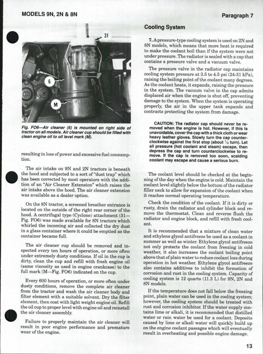
iViODELS 9N, 2N & 8N Paragraph 7 Fig. FO&-~Air cleaner (6) is mounted on right side of tractor on ail models. Air cleaner cup shouid be fiiied with ciean engine oil to oii level marii (M). resulting in loss of power and excessive fuel consump- tion. The air intake on 9N and 2N tractors is beneath the hood and subjected to a sort of "dust trap" which has been corrected by most operators with the addi- tion of an "Air Cleaner Extension" which raises the air intake above the hood. The air cleaner extension was available as a dealer option. On the 8N tractor, a screened breather entrance is located on the outside of the right rear comer of the hood. A centrifugal type (Cyclone) attachment (31— Fig. F06) was made available for 8N tractors which whirled the incoming air and collected the dry dust in a glass container where it could be emptied as the container became full. The air cleaner cup should be removed and in- spected every ten hours of operation, or more often under extremely dusty conditions. If oil in the cup is dirty, clean the cup and refill with fresh engine oil (same viscosity as used in engine crankcase) to the full mark (M—Fig. F06) indicated on the cup. Every 600 hours of operation, or more often under dusty conditions, remove the complete air cleaner from the tractor and wash the air cleaner body and filter element with a suitable solvent. Dry the filter element, then coat with light weight engine oil. Refill the oil cup to proper level with engine oil and reinstall the air cleaner assembly. Failure to properly maintain the air cleaner will result in poor engine performance and premature wear of the engine. Cooiing System 7. A pressure-type cooling system is used on 2N and 8N models, which means that more heat is required to make the coolant boil than if the system were not under pressure. The radiator is sealed with a cap that contains a pressure valve and a vacuum valve. The pressure valve in the radiator cap maintains cooHng system pressure at 3.5 to 4.5 psi (24-31 kPa), raising the boiling point of the coolant many degrees. As the coolant heats, it expands, raising the pressure in the system. The vacuum valve in the cap admits displaced air when the engine is shut off, preventing damage to the system. When the system is operating properly, the air in the upper tank expands and contracts protecting the system from damage. CAUTiON: The radiator cap shouid never be re- moved when the engine is hot. However, if this is unavoidabie, cover the cap with a thick cioth or wear heavy ieather gioves. Siowiy turn the cap counter- ciockwise against the first stop (about V4 turn). Let ail pressure (hot coolant and steam) escape, then depress the cap and turn counterciockwise to re- move. If the cap is removed too soon, scalding coolant may escape and cause a serious burn. The coolant level should be checked at the begin- ning of the day when the engine is cold. Maintain the coolant level slightly below the bottom of the radiator filler neck to allow for expansion of the coolant when it reaches normal operating temperature. Check the condition of the coolant. If it is dirty or rusty, drain the radiator and cylinder block and re- move the thermostat. Clean and reverse fiush the radiator and engine block, and refill with fresh cool- ant. It is recommended that a mixture of clean water and ethylene glycol antifreeze be used as a coolant in summer as well as winter. Ethylene glycol antifreeze not only protects the coolant from freezing in cold weather, it also increases the coolant boiling point above that of plain water to reduce coolant loss during operation in hot weather. Ethylene glycol antifreeze also contains additives to inhibit the formation of corrosion and rust in the cooling system. Capacity of cooling system is 12 quarts (11.3 L) for 9N, 2N and 8N models. If the temperature does not fall below the freezing point, plain water can be used in the cooling system; however, the cooling system should be treated with rust and corrosion inhibitor. If the water supply con- tains lime or alkali, it is recommended that distilled water or rain water be used for a coolant. Deposits caused by lime or alkali water will quickly build up on the engine coolant passages which will eventually result in overheating and possible engine damage. 13
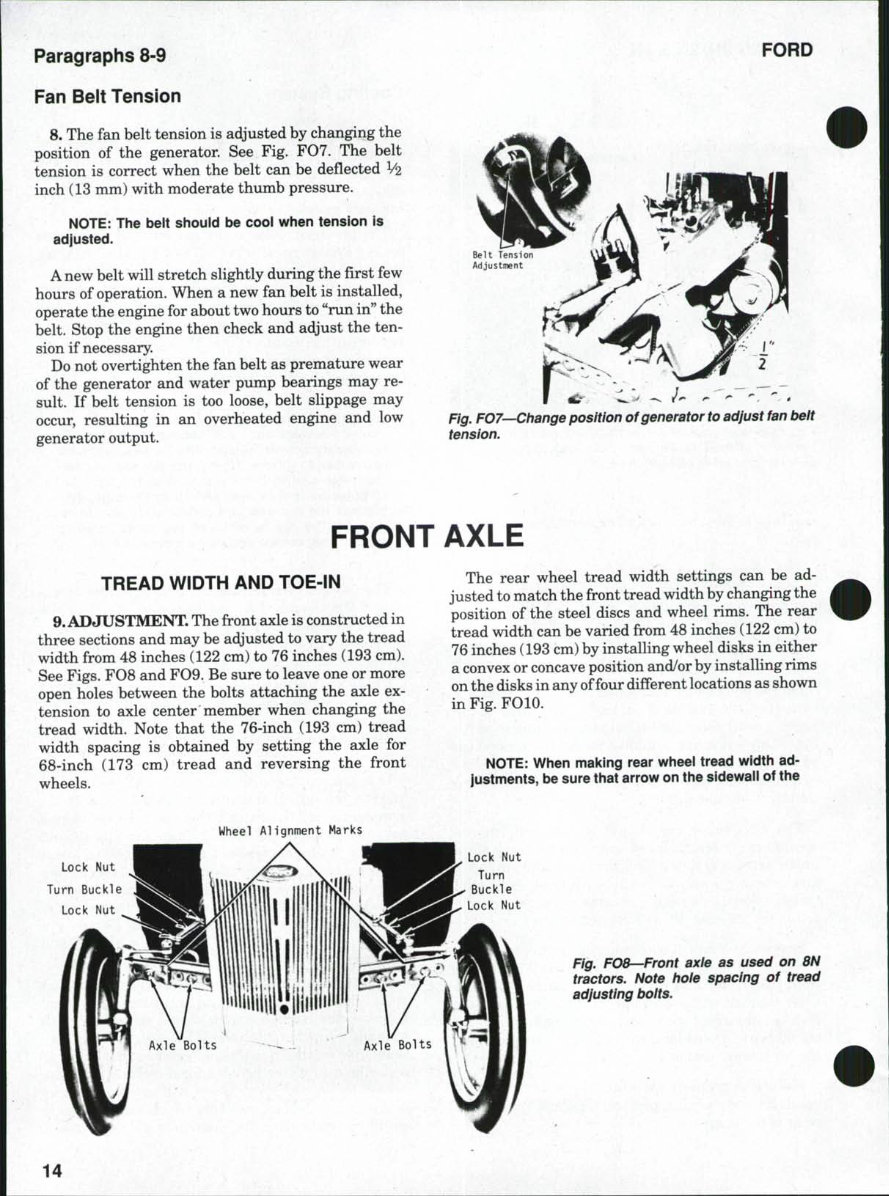
Paragraphs 8-9 FORD Fan Beit Tension 8. The fan belt tension is adjusted by changing the position of the generator. See Fig. F07. The belt tension is correct when the belt can be defiected V2 inch (13 mm) with moderate thumb pressure. NOTE: The belt should be cool when tension is adjusted. A new belt will stretch slightly during the first few hours of operation. When a new fan belt is installed, operate the engine for about two hours to "run in" the belt. Stop the engine then check and adjust the ten- sion if necessary. Do not overtighten the fan belt as premature wear of the generator and water pump bearings may re- sult. If belt tension is too loose, belt slippage may occur, resulting in an overheated engine and low generator output. Fig. FOl—Change position of generator to adjust fan belt tension. FRONT AXLE TREAD WiDTH AND TOE-iN 9. ADJUSTMENT. The front axle is constructed in three sections and may be adjusted to vary the tread width from 48 inches (122 cm) to 76 inches (193 cm). See Figs. F08 and F09. Be sure to leave one or more open holes between the bolts attaching the axle ex- tension to axle center member when changing the tread width. Note that the 76-inch (193 cm) tread width spacing is obtained by setting the axle for 68-inch (173 cm) tread and reversing the front wheels. ••?-•.. The rear wheel tread width settings can be ad- justed to match the front tread width by changing the position of the steel discs and wheel rims. The rear tread width can be varied from 48 inches (122 cm) to 76 inches (193 cm) by installing wheel disks in either a convex or concave position and/or by installing rims on the disks in any of four different locations as shown in Fig. FOIO. NOTE: When making rear wheel tread width ad- justments, be sure that arrow on the sidewail of the Wheel Alignment Marks Lock Nut Turn Buckle Lock Nut Lock Nut Turn Buckle Lock Nut flg^ FO8—Front axle as used on 8N tractors. Note hole spacing of tread adjusting boits. 14
You're Reading a Preview
What's Included?
Lifetime Access
Fast Download Speeds
Online & Offline Access
Access PDF Contents & Bookmarks
Full Search Facility
Print one or all pages of your manual
$31.99
1948-1952 Ford 8N Tractor OEM Service & Repair Manual
The 1948-1952 Ford 8N Tractor OEM Service & Repair Manual is a comprehensive guide designed for professional technicians and do-it-yourself mechanics. It provides essential information for maintaining and repairing the Ford 8N Tractor from the model years 1948-1952, covering both electrical and mechanical concepts.
This manual is an invaluable reference for vehicle and engine maintenance, encompassing topics typically found in factory service and owner's manuals. It is available in digital format and can be viewed on all versions of Windows and Mac using Adobe Reader.
Key features of the manual include:
Step-by-step repair procedures
Detailed specifications and illustrations
Maintenance, disassembly, assembly, cleaning, and reinstallation guidelines
Comprehensive coverage of engine removal, wiring diagrams, lubrication points, and periodic maintenance
In-depth information on engine servicing, fuel and lubrication systems, electrical systems, chassis, and suspension
Overall, the 1948-1952 Ford 8N Tractor OEM Service & Repair Manual is an indispensable resource for anyone seeking to effectively maintain and repair their tractor with reliable OEM guidelines.
Reviews
Q&A
Recently Viewed
5,521,897Happy Clients
2,594,462eManuals
1,120,453Trusted Sellers
15Years in Business
Price:
Actual Price:
1948-1952 Ford 8N Tractor OEM Service & Repair Manual