FORD 1320-1520 AND 1720 TRACTORS Repair Manual 40132030 SE4602 FORD NEW HOLLAND, (NO. NEW HOLLAND, PENNSYLVANIA PRINTED IN U.S.A.
FOREWORD This repair manual provides information for the proper servicing and overhaul of Ford 1320-1520 and 1720 Tractor Models and is an essential publication for all service personnel carrying out repairs and maintenance procedures. The Manual is divided into twelve PARTS, each sub-divided into Chapters. Each Chapter contains information on general operating principles, detailed inspection and overhaul and, where applicable, trouble shooting, special tools and specifications. The material contained in this Manual was correct at the time of going to print, but Ford New Holland, Inc. policy is one of continuous improvement and the right to change prices, specifica- tions, equipment or design at anytime without notice is reserved. All data in this Manual is subject to production variations, so overall dimensions and weights should be considered as approximate only and the illustrations do not necessarily depict the unit to standard build specification. FORD NEW HOLLAND, INC.
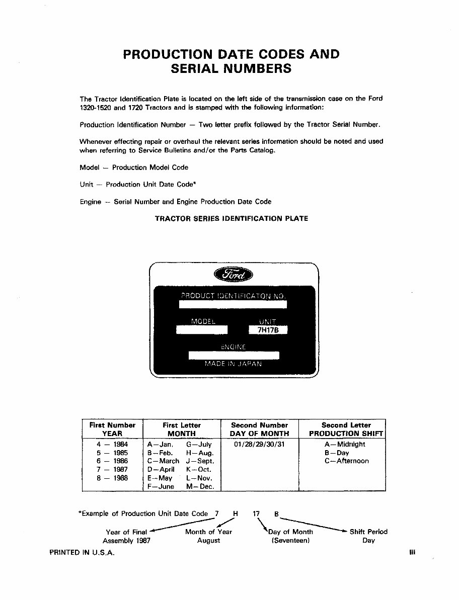
PRODUCTION DATE CODES AND SERIAL NUMBERS The Tractor Identification Plate is located on the left side of the transmission case on the Ford 1320-1520 and 1720 Tractors and is stamped with the following information: Production Identification Number — Two letter prefix followed by the Tractor Serial Number, Whenever effecting repair or overhaul the relevant series information should be noted and used when referring to Service Bulletins and/or the Parts Catalog, Model — Production Model Code Unit — Production Unit Date Code* Engine — Serial Number and Engine Production Date Code TRACTOR SERIES IDENTIFICATION PLATE First Number YEAR 4-1984 5 - 1985 6 - 1986 7 - 1987 8 - 1988 First Letter MONTH A—Jan. G-July B-Feb. H-Aug. C—March J—Sept. D—April K—Oct. E—May L—Nov. F—June M—Dec, Second Number DAY OF MONTH 01/28/29/30/31 Second Letter PRODUCTION SHIFT A- Midnight B — Day C—Afternoon Example of Production Unit Date Code 7 H 17 Year of Final Assembly 1987 PRINTED IN U.S.A. Month of Year August \ Day of Month (Seventeen) Shift Period Day Hi
SAFETY PRECAUTIONS Practically all service work involves the need to drive the tractor. The Operator's Manual, supplied with each tractor, contains detailed safety precautions relating to driving, operating and servicing that tractor. These precautions are as applicable to the service technician as they are to the operator, and should be read, understood and practiced by afl personnel. Prior to undertaking any maintenance, repair, overhaul, dismantling or re-assembly operations, whether within a workshop facility or out "in the field," consideration should be given to factors that may have an effect upon safety, not only upon the mechanic carrying out the work, but also upon bystanders. PERSONAL CONSIDERATIONS • The wrong clothes or carelessness in dress can cause accidents. Check to see that you are suitably clothed. Some jobs require special protective equipment. • Eye Protection The smallest eye injury may cause loss of vision. Injury can be avoided by wearing eye protection when engaged in chiselling, grinding, discing, welding, painting, etc. • Breathing Protection Fumes, dust and paint spray are unpleasant and harmful. These can be avoided by wearing respiratory protection. • Hearing Protection Loud noise may damage your hearing and the greater the exposure the worse the damage. If you feel the noise is excessive, wear ear protection. • Hand Protection It is advisable to use a protective cream before work to prevent irritation and skin contamination. After work clean your hands with soap and water. Solvents such as white spirit, paraffin, etc., may harm the skin. • Foot Protection Substantial or protective footwear with reinforced toe-caps will protect your feet from falling objects. Additionally, oil-resistant soles will help to avoid slipping. • Special Clothing For certain work it may be necessary to wear flame or acid-resistant clothing. • Avoid injury through incorrect handling of components. Make sure you are capable of lifting the object. If in doubt get help. EQUIPMENT CONSIDERATIONS • Machine Guards Before using any machine, check to ensure that the machine guards are in position and serviceable. These guards not only prevent parts of the body or clothing from coming in contact with the moving parts of the machine, but also ward off objects that might fly off the machine and cause injury. • Lifting Appliances Always ensure that lifting equipment, such as chains, slings, lifting brackets, hooks and eyes are thoroughly checked before use. If in doubt, select stronger equipment than is necessary. Never stand under a suspended load or a raised implement. • Compressed Air The pressure from a compressed air line is often as high as 100 psi (6.9 bar) 7 (kgf/cm 2 ). It is perfectly safe if used correctly. Any misuse may cause injury. Never use compressed air to blow dust, filing, dirt, etc., away from your work area unless the correct type of nozzle is fitted. Compressed air is not a cleaning agent, it will only move dust, etc., from one place to another. Look around before using an air hose as bystanders may get grit into their eyes, ears or skin. iv
• Hand Tools Many cuts, abrasions and! injuries are caused by defective tools. Never use the wrong tool for the job, as this generally leads either to some Injury, or to a poor job. i^Jever use — A hammer with a loose head or split handle, — Spanners or wrenches with splayed or worn Jaws. — Spanners or files as hammers; or drills, clevis pins or bolts as punches. For removing or replacing hardened pins use a copper or brass drift rather than a hammer. For dismantling, overhaul and assembly of major and sub components, always use the Special Service Tools recommended. These will reduce the work effort, labor time and the repair cost. Always keep tools clean and in good working order. • Electricity Electricity has become so familiar in day to day usage that its potentially dangerous properties are often over- looked. Misuse of electrical equipment can endanger life. Before using any electrical equipment — particularly portable appliances — make a visual check to make sure that the cable is not worn or frayed and that the plugs, sockets, etc., are intact. Make sure you know where the nearest isolating switch for your equipment is located, GENERAL CONSIDERATIONS • Solvents Use only cleaning fluids and solvents that are known to be safe. Certain types of fluids can cause damage to components such as seals, etc., and can cause skin irritation. Solvents should be checked that they are suitable not only for the cleaning of components and individual parts, but also that they do not the affect personal safety of the user. • Housekeeping Many injuries result from tripping or slipping over, or on, objects or material left lying around by a careless worker. Prevent these accidents from occurring. If you notice a hazard, don't ignore it — remove it, A clean, hazard-free place of work improves the surroundings and daily environment for everybody. • Fire Fire has no respect for persons or property. The destruction that a fire can cause is not always fully realized. Everyone must be constantly on guard. — Extinguish matches/cigars/cigarettes, etc., before throwing them away. — Work cleanly, disposing of waste material into proper containers. — Locate the fire extinguishers and find out how to operate them. — Do not panic — warn those near and raise the alarm, -~ Do not allow or use an open flame near the tractor fuel tank, battery or component parts, • First Aid In the type of work that mechanics are engaged in, dirt, grease, fine dusts, etc., all settle upon the skin and clothing, If a cut, abrasion or burn is disregarded it may be found that a septic condition has formed within a short time. What appears at first to be trivial could become painful and injurious. It only takes a few minutes to have a fresh cut dressed, but it will take longer if you neglect it. Make sure you know where the First Aid box is located. • Cleanliness Cleanliness of the tractor hydraulic system is essential for optimum performance. When carrying out service and repairs plug all hose ends and component connections to prevent dirt entry, Clean the exterior of all components before carrying out any form of repair. Dirt and abrasive dust can reduce the efficiency and working life of a component and lead to costly replacement, Use of a high pressure washer or steam cleaner Is recommended, PRINTED IN U.S.A. v
OPERATIONAL CONSIDERATIONS • Stop the engine, if at .all possible, before performing any service. • Place a warning sign on tractors which, due to service or overhaul, would be dangerous to start. Disconnect the battery leads if leaving such a unit unattended* • Do not attempt to start the engine while standing beside the tractor or attempt to by-pass the safety start switch. • Avoid prolonged running of the engine in a closed building or in an area with inadequate ventilation as exhaust fumes are highly toxic, • Always turn the radiator cap to the first stop, to allow pressure in the system to dissipate when the coolant is hot, • Never work beneath a tractor which is on soft ground. Always take the unit to an area which has a hard working surface — concrete for preference, • If it is found necessary to raise the tractor for ease of servicing or repair, make sure that safe and stable supports are installed beneath axle housings, casings, etc, before commencing work. • Certain repair or overhaul procedures may necessitate "separating the tractor/' either at the engine/front transmis- sion or front transmission/rear transmission locations. These operations are simplified by the use of the Tractor Splitting Kit/Stands. Should this equipment not be available, then every consideration must be given to stabili- ty, balance and weight of the components, especially if a cab is installed. • Use footsteps or working platforms when servicing those areas of a tractor that are not within easy reach. • Before loosening any hoses or tubes connecting implements to remote control valves, etc, switch off the engine, remove all pressure in the lines by operating levers several times. This will remove the danger of personal injury by oil pressure. • Prior to pressure testing, make sure all hoses and connectors not only of the tractor, but also those of the test equipment, are in good condition and tightly sealed. Pressure readings must be taken with the gauges specified. The correct procedure should be rigidly observed to prevent damage to the system or the equipment, and to eliminate the possibility of personal injury, • When equipment or implements are required to be attached to the hydraulic linkage, either for testing purposes or for transportation, then "position control" should be used. • Always lower equipment to the ground when leaving the tractor. • If high lift attachments are installed on a tractor beware of overhead power, electric or telephone cables when traveling. Drop attachment near to ground level to increase stability and minimize risks. • Do not park or attempt to- service a tractor on an incline. If unavoidable, take extra care and block all wheels, • Observe recommended precautions as indicated in this Repair Manual when dismantling the air conditioning system as escaping refrigerant can cause frostbite. • Prior to removing wheels and tires from a tractor, check to determine whether additional ballast (liquid or weights) has been added. Seek assistance and use suitable equipment to support the weight of the wheel assembly. • When inflating tires beware of over inflation — constantly check the pressure. Overinflation can cause tires to burst and result In personal injury. • Some components on your tractor, such as gaskets and friction surfaces (brake lining, clutch lining, etc.) may contain asbestos, Breathing asbestos dust Is dangerous to your health, You are therefore advised to have any maintenance or repair operation on such components carried out by an authorized Ford New Holland Dealer, If, however, service operations are to be undertaken on parts that contain asbestos, the essential precautions are listed below must be observed, — Work, out of doors or in a well ventilated area, — Dust found on tractor or produced during work on the tractor should be dampened, placed in a sealed container and marked to ensure safe disposal.
— If any cutting, drilling, etc., is attempted on materials containing asbestos, the item should be dampened and only hand tools or low speed power tools used, • Continuous long term contact with used engine oil may cause skin cancer. Avoid prolonged contact with used engine oil. Wash skin promptly with soap and water. Safety precautions are very seldom the figment of someone's imagination. They are the result of sad experience, where most likely someone has paid dearly through personal injury. Heed these precautions and you will protect yourself accordingly. Disregard them and you may duplicate the sad experience of others. SERVICE TECHNIQUES SERVICE SAFETY HOSES AMD TUBES Appropriate service methods and proper repair pro- cedures are essential for the safe, reliable operation of all equipment as well as the personal safety of the in- dividual doing the work. This Shop Manual provides general directions for accomplishing service and repair work with tested, effective techniques. Following them will help assure reliability. There are numerous variations in procedures, tech- niques, tools, and parts for servicing equipment, as well as in the skill of the individual doing the work. This Manual cannot possibly anticipate all such variations and provide advice or cautions as to each. According- ly, anyone who departs from the instructions provided in this Manual must first establish that he compromises neither his personal safety nor the equipment integrity by his choice of methods, tools or parts. B. SERVICE TECHNIQUES Clean the exterior of ail components before carrying out any form of repair. Dirt and abrasive dust can reduce the efficient working life of a component and lead to costly replacement. Time spent on the preparation and cleanliness of work- ing surfaces will pay dividends in making the Job easier and safer and will result in overhauled components be- ing more reliable and efficient in operation. Use cleaning fluids which are known to be safe, Cer- tain types of fluid can cause damage to 'O' rings and cause skin irritation, Solvents should be checked that they are suitable for the cleaning of components and also that they do not risk the personal safety of the user. Replace '0' rings, seals or gaskets whenever they are disturbed. Never mix new and old seals or '0' rings, regardless of condition. Always lubricate new seals and '0' rings with hydraulic oil before installation, When replacing component parts use the correct tool for the Job, PRINTED IN U.S.A. Always replace hoses and tubes if the cone end or the end connections are damaged. When installing a new hose loosely connect each end and make sure the hose takes up the designed position before tightening the connection. Clamps should be tightened sufficiently to hold the hose without crushing and to prevent chafing. The hoses are the arteries of the unit, be sure they are in good condition when carrying out repairs or maintenance, otherwise the machine's output and pro- ductivity will be affected. After replacing a hose on a moving component make sure the hose does not foul by moving the component through its complete range of travel. Be sure any hose which has been installed is not ksnked or twisted. Hose connections which are damaged, dented, crushed or leaking restrict oil flow and the productivity of the components being served. Connectors which show signs of movement from the original swaged position have failed, and will ultimately separate completely. A hose with a chafed outer cover will allow water en- try. Concealed corrosion of the wire reinforcement will subsequently occur along the hose length with resul- tant hose failure. Ballooning of the hose indicates an internal leakage due to structural failure. This condition rapidly deteriorates and total hose failure soon occurs. Kinked, crushed, stretched or deformed hoses generally suffer internal structural damage which can result in oil restriction, a reduction in the speed of operation and ultimate hose failure. Free-moving, unsupported hoses must never be allowed to touch each other or related working surfaces. This causes chafing which reduces hose life. vii
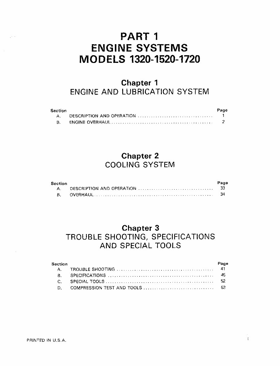
PART 1 ENGINE SYSTEMS MODELS 1320-1B20-1720 Chapter 1 ENGINE AND LUBRICATION SYSTEM Section Page A, DESCRIPTION AND OPERATION .................................. 1 B. ENGINE O V E R H A U L .............................................. 2 Chapter 2 COOLING SYSTEM Section A. DESCRIPTION AND OPERATION 33 B. OVERHAUL 34 Chapter 3 TROUBLE SHOOTING, SPECIFICATIONS AND SPECIAL TOOLS Section Page A. TROUBLE SHOOTING ............................................ 41 8. SPECIFICATIONS ................................................ 45 C. SPECIAL TOOLS 52 D. COMPRESSION TEST AND TOOLS ................................ 53 PRINTED IN U.S.A.
PART 1 ENGINE SYSTEMS MODELS 1320-1520-1720 Chapter 1 ENGINE AND LUBRICATION SYSTEM Section A. DESCRIPTION AND OPERATION B. ENGINE O V E R H A U L ............ Page 1 2 A, DESCRIPTION AND OPERATION This chapter describes the engine overhaul and repair procedures of the Models 1320-1520 and 1720 tractors. Repair procedures are essentially the same for all models except as noted in the repair procedures, The tractors are equipped with three-cylinder in-line engines. They are all four cycle, overhead valve, liquid cooled engines. The engines are identified by a code number cast into the side of the cylinder block. Engine Identification J823 J843 N843 Tractor Model 1320 1520 1720 Horsepower 19.0 22.0 28,5 Cylinder heads have integral valve guides, Standard size valves only are used. CYLINDER BLOCK ASSEMBLY The cylinder block assembly contains the pistons, con- necting rods, crankshaft, timing gears and engine oil pump. The crankshaft is supported on four main bearings, The front bearing is positioned in a bore in the front of the block. The 2nd, 3rd and 4th bearings are split liners located in holders bolted to the block. The camshaft is supported on two bail bearings located on each end of the block, CYLINDER HEAD AND VALVE TRAIN COMPONENTS The cylinder head incorporates the valve assemblies, rocker arms, rocker shaft, push rods, and lifters. A swirl chamber located between the injector assembly and the main combustion chamber of the cylinders pro- vides improved starting and greater fuel efficiency, in- itial combustion starts in the pre-combustion chamber and as the air-fuel expansion occurs a strong swiri pat- tern is created in the main combustion chamber for more complete combustion of the air-fuel mixture. The air intake manifold is separated from the cast aluminum valve cover on all of these engines, The ex- haust manifold is bolted to the left hand side of the cylinder head on each of the models. PRINTED IN U.S.A. PISTON AND CONNECTING RODS All models utilize a straight connecting rod and a three ring piston. LUBRICATION SYSTEM Models - All The oil pump assembly is located within the injection pump drive gear at the front of the block and below and to the left of the crankshaft as viewed from the front. The oil pump is driven by the crankshaft gear. Oil is picked up from the sump by the intake tube and drawn into the lower side drilling in the block to the oil pump, Oil from the pump flows through passages in the block,, past the relief valve, through the oil filter and 1
This professional technical manual contains service, maintenance, and troubleshooting information for your Ford 1720 Tractor, covering all models, engines, trim, and transmission types. It is useful for both professional mechanics and DIY enthusiasts.
The manual includes detailed information on the following:
Ford 1720 Tractor Engine
Ford 1720 Tractor Lubrication System
Ford 1720 Tractor Cooling System
Ford 1720 Tractor Fuel System
Ford 1720 Tractor Disassembly and Servicing
Ford 1720 Tractor General
Ford 1720 Tractor Separation
Ford 1720 Tractor Clutch
Ford 1720 Tractor Transmission
Ford 1720 Tractor Drive Chain & Sprockets
Ford 1720 Tractor Rear Axle
Ford 1720 Tractor Brakes
Ford 1720 Tractor Front Axle
Ford 1720 Tractor Steering
Ford 1720 Tractor Shocks
Ford 1720 Tractor Body Work
Ford 1720 Tractor Intake & Exhaust
Ford 1720 Tractor Hydraulic System
Ford 1720 Tractor Electrical System
Ford 1720 Tractor Routine Maintenance
Ford 1720 Tractor Advanced Troubleshooting
Ford 1720 Tractor Wiring Diagram
Plus a lot more info!
This manual is available in electronic format, allowing for easy access and printing of specific sections for use during repairs or services. It provides step-by-step repair procedures, critical specifications, illustrations, maintenance, disassembly, assembly, cleaning, and reinstalling procedures.
Product Details:
File Format: PDF
Language: English
Specifications: Full Printable
Zoom IN/OUT: Yes
Delivery: Instant
Requirements: Adobe Reader & WinZip
Compatible: All Versions of Windows & Mac
This Ford 1720 Tractor Workshop Repair Service Manual is a comprehensive resource for anyone working on the vehicle, providing detailed substeps, notes, cautions, warnings, numbered instructions, illustrations, and troubleshooting and electrical service procedures with wiring diagrams for ease of use.