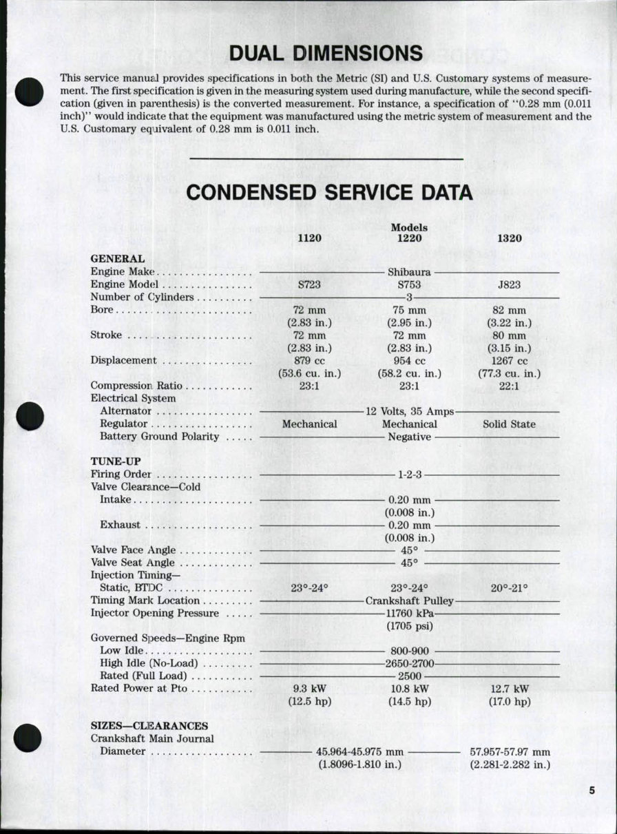
DUAL DIMENSIONS This service manugJ provides specifications in both the Metric (SI) and U.S. Customary systems of measure- ment. The first specification is given in the measuring system used during manufacture, while the second specifi- cation (given in pai'enthesis) is the converted measurement. For instance, a specification of *'0.28 mm (0.011 inch)" would indicate that the equipment was manufactured using the metric system of measurement and the U.S. Customary equivalent of 0.28 mm is 0.011 inch. CONDENSED SERVICE DATA Models 1120 1220 1320 GENERAL Engine Make; Shibaura Engine Mod(d S723 S753 J823 Number of CJylinders 3- Bore 72 mm 75 mm 82 mm (2.83 in.) (2.95 in.) (3.22 in.) Stroke 72 mm 72 mm 80 mm (2.83 in.) (2.83 in.) (3.15 in.) Displacement 879 cc 954 cc 1267 cc (53.6 cu. in.) (58.2 cu. in.) (77.3 cu. in.) Compression Ratio 23:1 23:1 22:1 Electrical System Alternator 12 Volts, 35 Amps- Regulator Mechanical Mechanical Solid State Battery Ground Polarity Negative TUNE-UP Firing Order 1-2-3 Valve Cleara,nce—Cold Intake 0.20 mm (0.008 in.) Exhaust 0.20 mm (0.008 in.) Valve Face Angle 45° Valve Seat i^ngle 45° Irgection Timing- Static, BTDC 23°-24*^ 23°-24° 20°-21° Timing Mark Location Crankshaft Pulley Iryector Opening Pressure 11760 kPa (1705 psi) Governed SjDeeds-Engine Rpm Low Idle. 800-900 High Idle (No-Load) 2650-2700 Rated (FuU Load) 2500 Rated Power at Pto 9.3 kW 10.8 kW 12.7 kW (12.5 hp) (14.5 hp) (17.0 hp) SIZES—CLISARANCES Crankshaft Main Journal Diameter 45.964-45.975 mm 57.957-57.97 mm (1.8096-1.810 in.) (2.281-2.282 in.)
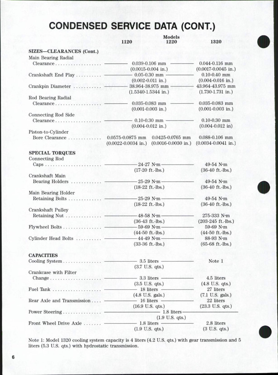
CONDENSED SERVICE DATA (CONT.) 1120 Models 1220 1320 SIZES—CLEARANCES (Cont.) Main Bearing Radial Clearance 0.039-0.106 mm 0.044-0,116 mm (0.0015-0.004 in.) (0.0017-0.0045 in.) Crankshaft End Play 0.05-0.30 mm 0.10-0.40 mm (0.002-0.011 in.) (0.004-0.016 in.) Crankpin Diameter 38.964-38.975 mm 43.964-43.975 mm (1.5340-1.5344 in.) (1.730-1.731 in.) Rod Bearing Radial Clearance 0.035-0.083 mm 0.035-0.083 mm (0.001-0.003 in.) (0.001-0.003 in.) Connecting Rod Side Clearance 0.10-0.30 mm 0.10-0.30 mm (0.004-0.012 in.) (0.004-0.012 in) Piston-to-Cylinder Bore Clearance 0.0575-0.0875 mm 0.0425-0.0765 mm 0.088-0.106 mm (0.0022-0.0034 in.) (0.0016-0.0030 in.) (0.0034-0.0041 in.) SPECIAL TORQUES Connecting Rod Caps 24-27 N-m 49-54 N-m (17-20 ft.-lbs.) (36-40 ft.-lbs.) Crankshaft Main Bearing Holders 25-29 N-m 49-54 N-m (18-22 ft.-lbs.) (36-40 ft.-lbs.) Main Bearing Holder Retaining Bolts 25-29 N-m 49-54 N-m (18-22 ft.-lbs.) (36-40 ft.-lbs.) Crankshaft Pulley Retaining Nut —48-58 N-m 275-333 N-m (36-43 ft.-lbs.) (203-245 ft.-lbs.) Flywheel Bolts 59-69 N-m 59-69 N-m (44-50 ft.-lbs.) (44-50 ft.-lbs.) Cylinder Head Bolts 44-49 N-m 88-93 N-m (33-36 ft.-lbs.) (65-68 ft.-lbs.) CAPACITIES Cooling System 3.5 liters Note 1 (3.7 U.S. qts.) Crankcase with Filter Change 3.3 liters 4.5 liters (3.5 U.S. qts.) (4.8 U.S. qts.) Fuel Tknk — — 18 liters 27 liters (4.8 U.S. gals.) (7.1 U.S. gals.) Rear Axle and Transmission .... 16 liters 22 liters (16.9 U.S. qts.) (23.3 U.S. qts.) Power Steering L8 liters (1.9 U.S. qts.) Front Wheel Drive Axle 1.8 liters 2.8 liters (1.9 U.S. qts.) (3 U.S. qts.) Note 1: Model 1320 cooling system capacity is 4 liters (4.2 U.S. qts.) with gear transmission and 5 liters (5.3 U.S. qts.) with hydrostatic transmission.
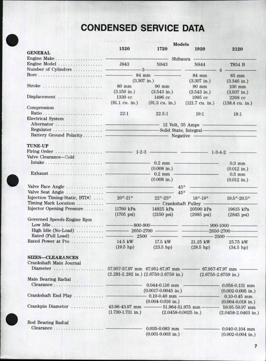
CONDENSED SERVICE DATA Models 1520 1720 1920 2120 GENERAL Engine Make Shibaura Engine Model J843 N843 N844 T854 B Number of Cylinders 3 4 Bore 84 mm 84 mm 85 mm (3.307 in.) (3.307 in.) (3.346 in.) Stroke 80 mm 90 mm 90 mm 100 mm (3.150 in.) (3.543 in.) (3.543 in.) (3.937 in.) Displacement 1330 cc 1496 cc 1995 cc 2268 cc (81.1 cu. in.) (91.3 cu. in.) (121.7 cu. in.) (138.4 cu. in.) Compression Ratio 22:1 22.5:1 19:1 18:1 Electrical System Alternator 12 Volt, 35 Amps Regulator Solid State, Integral Battery Ground Polarity Negative TUNE-UP Firing Order 1-2-3 1-3-4-2 Valve Clearance—Cold Intake 0.2 mm 0.3 mm (0.008 in.) (0.012 in.) Exhaust 0.2 mm 0.3 mm (0.008 in.) (0.012 in.) Valve Face Angle 45*^ Valve Seat Angle 45° Iryection Timing-Static, BTDC 20°-21° 22^-23° 18°-19° 19.5^-20.5° Timing Mark Location Crankshaft Pulley Iryector Opening Pressure 11760 kPa 14825 kPa 20590 kPa 19615 kPa (1705 psi) (2150 psi) (2985 psi) (2845 psi) Governed Speeds Engine Rpm Low Idle 800-900 900-1000 High Idle (No-Load) 2650-2700 2650-2700 Rated (Full Load) 2500 2500 Rated Power at Pto 14.5 kW 17.5 kW 21.25 kW 25.75 kW (19.5 hp) (23.5 hp) (28.5 hp) (34.5 hp) SIZES—CLEAR^.NCES Crankshaft Main Journal Diameter . 57.957-57.97 mm 67.951-67.97 mm 67.957-67.97 mm (2.281-2.282 in.) (2.6750-2.6759 in.) (2.6755-2.6759 in.) Main Bearing Radial Clearance 0.044-0.116 mm 0.056-0.131 mm (0.0017-0.0045 in.) (0.002-0.005 in.) Crankshaft End Play 0.10-0.40 mm 0.10-0.45 mm (0.004-0.016 in.) (0.004-0.018 in.) Crankpin Diameter 43.96-43.97 mm 51.964-51.975 mm 59.95-59.97 mm (1.730-1.731 in.) (2.0458-0.0025 in.) (2.0458-2.0463 in.) Rod Bearing Radial Clearance 0.035-0.083 mm 0.040-0.104 mm (0.001-0.003 in.) (0.002-0.004 in.)
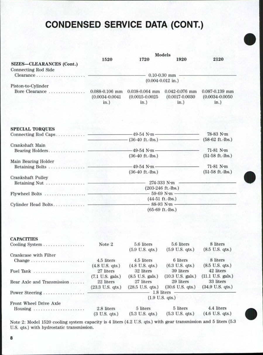
CONDENSED SERVICE DATA (CONT.) SIZES—CLEARANCES (Cont.) Connecting Rod Side Clearance 1520 1720 Models 1920 Piston-to-Cylinder Bore Clearance . 0.088-0.106 mm (0.0034-0.0041 in.) - 0.10-0.30 mm - (0.004-0.012 in.) 0.038-0.064 mm (0.0015-0.0025 in.) 0.042-0.076 mm (0.0017-0.0030 in.) 2120 0.087-0.139 mm (0.0034-0.0050 in.) SPECIAL TORQUES Connecting Rod Caps. Crankshaft Main Bearing Holders. . . . Main Bearing Holder Retaining Bolts . . . . Crankshaft Pulley Retaining Nut Flywheel Bolts Cylinder Head Bolts. . 49-54 N-m- (36-40 ft.-lbs.) 49-54 N-m- (36-40 ft.-lbs.) -49-54 N-m- (36-40 ft.-lbs.) 274-333 N-m (203-246 ft.-lbs.) — 59-69 N-m — (44-51 ft.-lbs.) — 88-93 N-m — (65-69 ft.-lbs.) 78-83 N-m (58-62 ft.-lbs.) 71-81 N-m (51-58 ft.-lbs.) 71-81 N-m (51-58 ft.-lbs.) CAPACITIES Cooling System Note 2 Crankcase with Filter Change 4.5 liters (4.8 U.S. qts.) Fuel Tknk 27 liters (7.1 U.S. gals.) Rear Axle and Transmission 22 liters (23.3 U.S. qts.) Power Steering Front Wheel Drive Axle Housing 2.8 liters (3 U.S. qts.) 5.6 liters (5.9 U.S. qts.) 4.5 liters (4.8 U.S. qts.) 32 liters (8.5 U.S. gals.) 27 liters (28.5 U.S. qts.) 5.6 liters (5.9 U.S. qts.) 6 liters (6.3 U.S. qts.) 39 liters (10.3 U.S. gals.) 29 liters (30.6 U.S. qts.) 8 liters (8.5 U.S. qts.) 8 liters (8.5 U.S. qts.) 42 liters (11.1 US. gals.) 33 liters (34.9 U.S. qts.) 1.8 liters (1.9 U.S. qts.) 5 liters (5.3 U.S. qts.) 5 liters (5.3 U.S. qts.) 4.4 liters (4.6 U.S. qts.) Note 2: Model 1520 cooling system capacity is 4 liters (4.2 U.S. qts.) with gear transmission and 5 liters (5.3 U.S. qts.) with hydrostatic transmission. 8
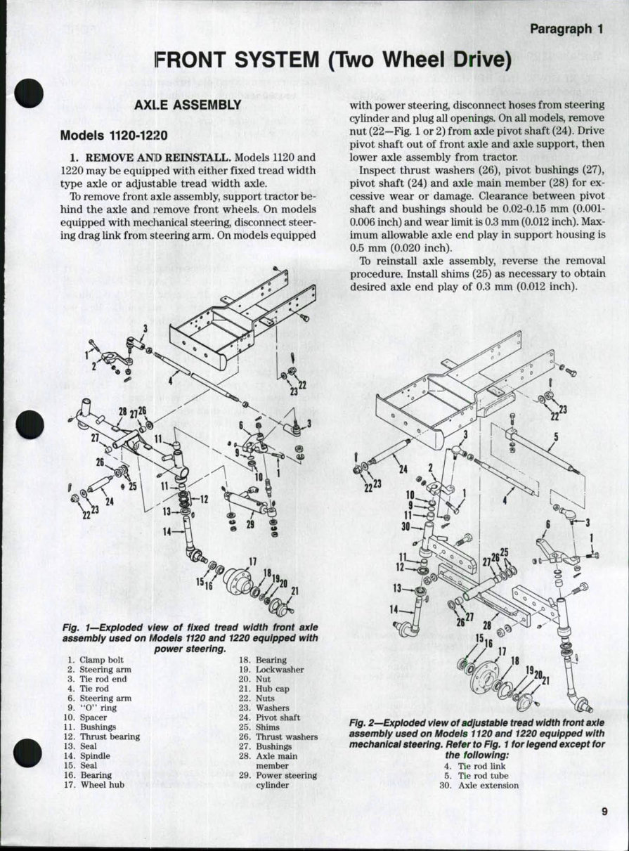
Paragraph 1 FRONT SYSTEM (Two Wheel Drive) AXLE ASSEMBLY Models 1120-12:20 1, REMOVE AN]D REINSTALL. Models 1120 and 1220 may be equipped with either fixed tread width type axle or adjustable tread width axle. Tb remove front axle assembly, support tractor be- hind the axle and I'emove front wheels. On models equipped with meclianical steering, disconnect steer- ing drag link from steering arm. On models equipped Fig, 1—Exploded view of assembly used on i^odels power 1. Clamp bolt 2. Steering arm 3. Tie rod end 4. Tie rod 6. Steering arm 9. " 0 " ring 10. Spacer 11. Bushings 12. Thrust bearing 13. Seal 14. Spindle 15. Seal 16. Bearing 17. Wheel hub fixed tread width front axie 1120 and 1220 equipped with steering. 18. Bearing 19. Lockwasher 20. Nut 21. Hub cap 22. Nuts 23. Washers 24. Pivot shaft 25. Shims 26. Thrust washers 27. Bushings 28. Axle main member 29. Power steering cylinder with power steering, disconnect hoses from steering cylinder and plug all openings. On all models, remove nut (22—Fig. 1 or 2) from axle pivot shaft (24). Drive pivot shaft out of front axle and axle support, then lower axle assembly from tractor. Inspect thrust washers (26), pivot bushings (27), pivot shaft (24) and axle main member (28) for ex- cessive wear or damage. Clearance between pivot shaft and bushings should be 0.02-0.15 mm (0.001- 0.006 inch) and wear limit is 0.3 mm (0.012 inch). Max- imum allowable axle end play in support housing is 0.5 mm (0.020 inch). Tb reinstall axle assembly, reverse the removal procedure. Install shims (25) as necessary to obtain desired axle end play of 0.3 mm (0.012 inch). Fig. 2—Expioded view ofadjustabie tread width front axle assembiy used on Modeis 1120 and 1220 equipped with mechanicai steering. Refer to Fig. 1 for iegend except for the foiiowing: 4, Tie rod link 5. Tie rod tube 30. Axle extension 9
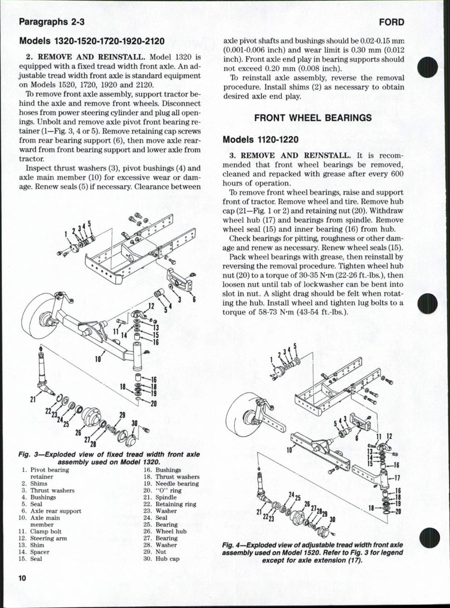
Paragraphs 2-3 FORD Models 1320-1520-1720-1920-2120 2. REMOVE AND REINSTALL. Model 1320 is equipped with a fixed tread width front axle. An ad- justable tread width front axle is standard equipment on Models 1520, 1720, 1920 and 2120. Ib remove front axle assembly, support tractor be- hind the axle and remove front wheels. Disconnect hoses from power steering cylinder and plug all open- ings. Unbolt and remove axle pivot front bearing re- tainer (1—Fig. 3, 4 or 5). Remove retaining cap screws from rear bearing support (6), then move axle rear- ward from front bearing support and lower axle from tractor. Inspect thrust washers (3), pivot bushings (4) and axle main member (10) for excessive wear or dam- age. Renew seals (5) if necessary. Clearance between 21 22 27 21 Fig. 3^Exploded view of fixed tread width front axie assembiy used on Modei 1320. 1. Pivot bearing , 16. Bushings retainer 18. Thrust washers 2. Shims 19. Needle bearing 3. Thrust washers 20. "O" ring 4. Bushings • 21. Spindle 5. Seal 22. Retaining ring 6. Axle rear support 23. Washer 10. Axle main 24. Seal member 25. Bearing 11. Clamp bolt 26. Wheel hub 12. Steering arm /; 27. Bearing 13. Shim 28. Washer 14. Spacer 29. Nut 15. Seal 30. Hubcap axle pivot shafts and bushings should be 0.02-0.15 mm (0.001-0.006 inch) and wear limit is 0.30 mm (0.012 inch). Front axle end play in bearing supports should not exceed 0.20 mm (0.008 inch). Ib reinstall axle assembly, reverse the removal procedure. Install shims (2) as necessary to obtain desired axle end play. FRONT WHEEL BEARINGS Models 1120-1220 3. REMOVE AND REINSTALL, It is recom- mended that front wheel bearings be removed, cleaned and repacked with grease after every 600 hours of operation. Ib remove front wheel bearings, raise and support front of tractor. Remove wheel and tire. Remove hub cap (21—Fig. 1 or 2) and retaining nut (20). Withdraw wheel hub (17) and bearings from spindle. Remove wheel seal (15) and inner bearing (16) from hub. Check bearings for pitting, roughness or other dam- age and renew as necessary. Renew wheel seals (15). Pack wheel bearings with grease, then reinstall by reversing the removal procedure. Tighten wheel hub nut (20) to a torque of 30-35 N-m (22-26 ft.-lbs.), then loosen nut until tab of lockwasher can be bent into slot in nut. A slight drag should be felt when rotat- ing the hub. Install wheel and tighten lug bolts to a torque of 58-73 N-m (43-54 ft.-lbs.). 20 Fig. 4—Expioded view of adjustable tread width front axie assembly used on Modei 1520. Refer to Fig. 3 for iegend except for axle extension (17). 10
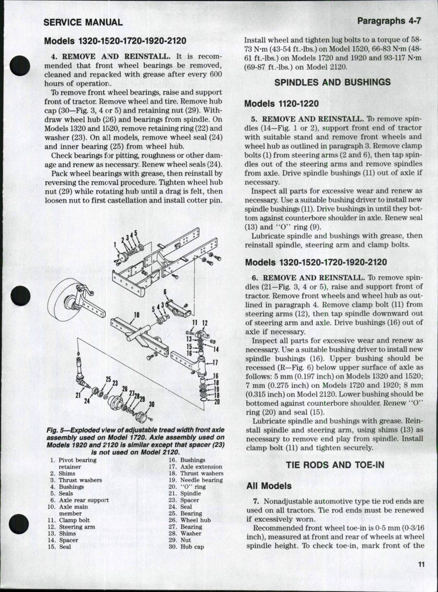
SERVICE MANUAL Paragraphs 4-7 Models 1320-1520-1720-1920-2120 4. REMOVE AND REINSTALL. It is recom- mended that front wheel bearings be removed, cleaned and repacked with grease after every 600 hours of operatiori. To remove front wheel bearings, raise and support front of tractor. Remove wheel and tire. Remove hub cap (30—Fig. 3, 4 or 5) and retaining nut (29). With- draw wheel hub (26) and bearings from spindle. On Models 1320 and 1520, remove retaining ring (22) and washer (23). On all models, remove wheel seal (24) and inner bearing (25) from wheel hub. Check bearings for pitting, roughness or other dam- age and renew as necessary. Renew wheel seals (24). Pack wheel bearings with grease, then reinstall by reversing the removal procedure. Tighten wheel hub nut (29) while rotating hub until a drag is felt, then loosen nut to first castellation and install cotter pin. Fig. 5—Expioded view ofadjustabie tread width front axle assembiy used on Modei 1720. Axie assembiy used on Modeis 1920 and 2120 is simiiar except that spacer (23) is not used on Modei 2120. 1. Pivot bearing retainer 2. Shims 3. Thrust washers 4. Bushings 5. Seals 6. Axle rear support 10. Axle main member 11. Clamp bolt 12. Steering arm 13. Shims 14. Spacer 15. Seal 16. Bushings 17. Axle extension 18. Thrust washers 19. Needle bearing 20. ' ' 0 " ring 21. Spindle 23. Spacer 24. Seal 25. Bearing 26. Wheel hub 27. Bearing 28. Washer 29. Nut 30. Hub cap Install wheel and tighten lug bolts to a torque of 58- 73 N-m (43-54 ft.-lbs.) on Model 1520, 66-83 N-m (48- 61 ft.-lbs.) on Models 1720 and 1920 and 93-117 N-m (69-87 ft.-lbs.) on Model 2120. SPINDLES AND BUSHINGS Models 1120-1220 5. REMOVE AND REINSTALL. To remove spin- dles (14—Fig. 1 or 2), support front end of tractor with suitable stand and remove front wheels and wheel hub as outlined in paragraph 3. Remove clamp bolts (1) from steering arms (2 and 6), then tap spin- dles out of the steering arms and remove spindles from axle. Drive spindle bushings (11) out of axle if necessary. Inspect all parts for excessive wear and renew as necessary. Use a suitable bushing driver to install new spindle bushings (11). Drive bushings in until they bot- tom against counterbore shoulder in axle. Renew seal (13) and "0'* ring (9). Lubricate spindle and bushings with grease, then reinstall spindle, steering arm and clamp bolts. Models 1320-1520-1720-1920-2120 6. REMOVE AND REINSTALL. To remove spin- dles (21—Fig. 3, 4 or 5), raise and support front of tractor. Remove front wheels and wheel hub as out- lined in paragraph 4. Remove clamp bolt (11) from steering arms (12), then tap spindle downward out of steering arm and axle. Drive bushings (16) out of axle if necessary. Inspect all parts for excessive wear and renew as necessary. Use a suitable bushing driver to install new spindle bushings (16). Upper bushing should be recessed (R—Fig. 6) below upper surface of axle as follows: 5 mm (0.197 inch) on Models 1320 and 1520; 7 mm (0.275 inch) on Models 1720 and 1920; 8 mm (0.315 inch) on Model 2120. Lower bushing should be bottomed against counterbore shoulder. Renew **0" ring (20) and seal (15). Lubricate spindle and bushings with grease. Rein- stall spindle and steering arm, using shims (13) as necessary to remove end play from spindle. Install clamp bolt (11) and tighten securely. TIE RODS AND TOE-IN All Models 7. Nonadjustable automotive type tie rod ends are used on all tractors. Tie rod ends must be renewed if excessively worn. Recommended front wheel toe-in is 0-5 mm (0-3/16 inch), measured at front and rear of wheels at wheel spindle height. Tb check toe-in, mark front of the 11
Welcome to the Ford 1520 Tractor Factory Service Repair Manual! This comprehensive manual is a must-have for anyone who owns or works with the Ford 1520 Tractor. Whether you are a professional mechanic or a DIY enthusiast, this manual provides detailed instructions and diagrams to help you maintain, repair, and troubleshoot your tractor with ease.
Key features of the Ford 1520 Tractor Factory Service Repair Manual include:
Step-by-step procedures for all maintenance and repair tasks
Clear and detailed diagrams and illustrations
Troubleshooting guides to help you identify and solve issues quickly
Specifications and technical data for the Ford 1520 Tractor
Tips and recommendations for optimal performance and longevity
With this manual at your fingertips, you can save time and money by performing repairs and maintenance tasks on your Ford 1520 Tractor yourself. Say goodbye to costly trips to the mechanic and hello to a well-maintained and efficient tractor!
Don't wait until it's too late - get your hands on the Ford 1520 Tractor Factory Service Repair Manual today and ensure that your tractor remains in top condition for years to come.