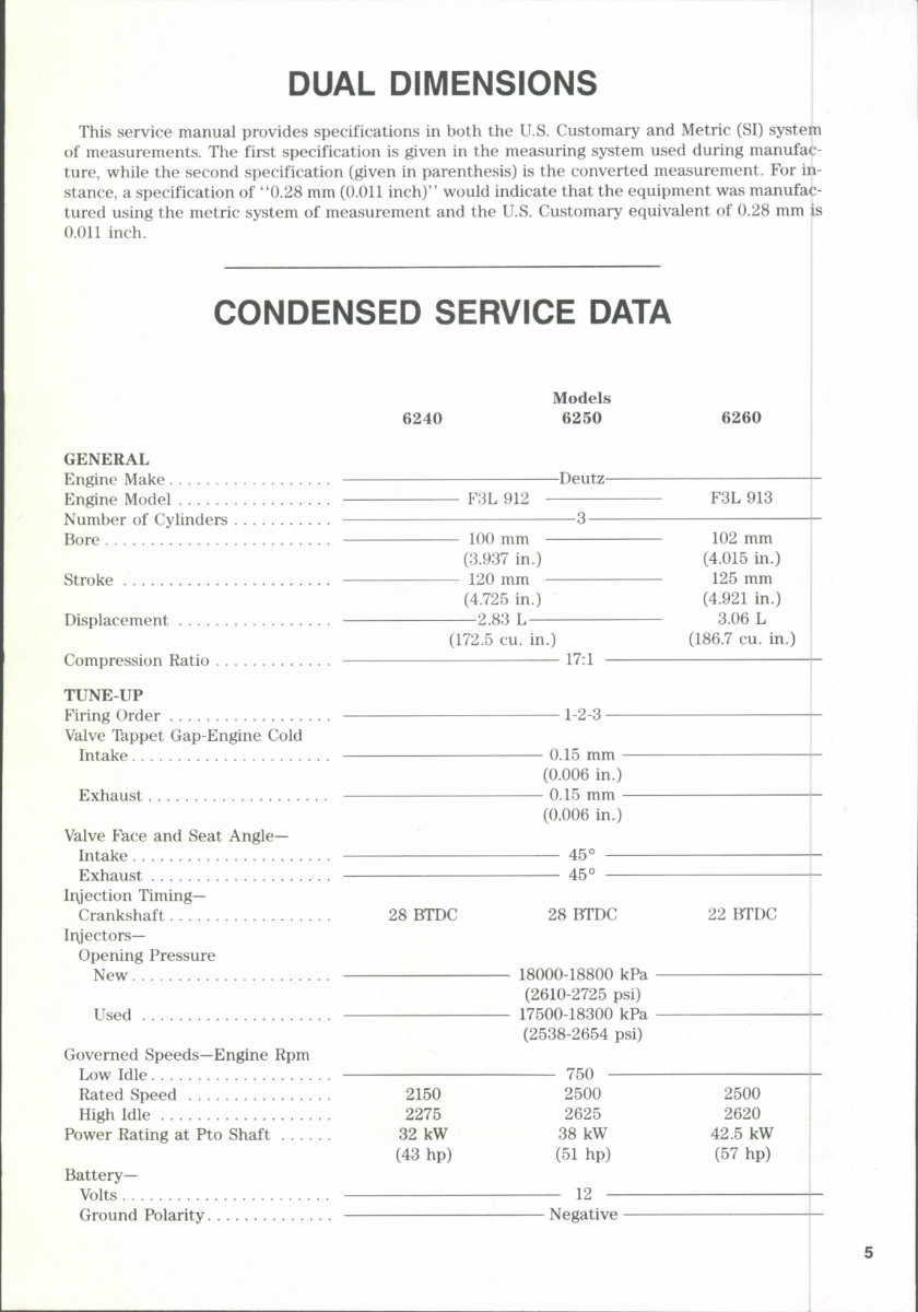
DUAL DIMENSIONS This service manual provides specifications in both the U.S. Customary and Metric (SI) system of measurements. The first specification is given in the measuring system used during manufac- ture, while the second specification (given in parenthesis) is the converted measurement. For in- stance, a specification of "0.28 mm (0.011 inch)'' would indicate that the equipment was manufac- tured using the metric system of measurement and the U.S. Customary equivalent of 0.28 mm is 0.011 inch. CONDENSED SERVICE DATA 6240 Models 6250 6260 GENERAL Engine Make Engine Model Number of Cylinders Bore Stroke Displacement Compression Ratio TUNE UP Firing Order Valve Tkppet Gap-Engine Cold Intake Exhaust Valve Face and Seat Angle- Intake Exhaust Iryection Timing- Crankshaft Iryectors— Opening Pressure New Used Governed Speeds—Engine Rpm Low Idle Rated Speed High Idle Power Rating at Pto Shaft Battery- Volts Ground Polarity -Deutz- F3L 912 F3L 913 100 mm (3.937 in.) - 120 mm - (4.725 in.) —2.83 L — (172.5 CU. in.) 102 mm (4.015 in.) 125 mm (4.921 in.) 3.06 L (186.7 CU. in.) 17:1 1-2-3 • - 0.15 mm - (0.006 in.) - 0.15 mm - (0.006 in.) 45° 45° 28 BTDC 28 BTDC 18000-18800 kPa (2610-2725 psi) 17500-18300 kPa (2538-2654 psi) 22 BTDC 2150 2275 32 kW (43 hp) - 750 - 2500 2625 38 kW (51 hp) 2500 2620 42.5 kW (57 hp) 12 Negative www.classicmachinery.net
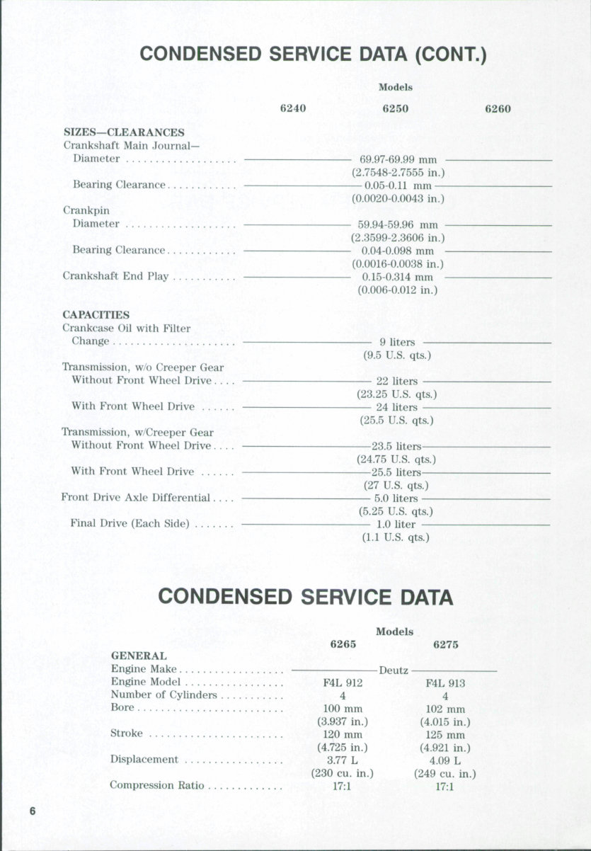
CONDENSED SERVICE DATA (CONT.) 6240 SIZES—CLEARANCES Crankshaft Main Journal- Diameter Bearing Clearance Crankpin Diameter Bearing Clearance Crankshaft End Play CAPACITIES Crankcase Oil with Filter Change Transmission, w/o Creeper Gear Without Front Wheel Drive. . . With Front Wheel Drive Transmission, w/Creeper Gear Without Front Wheel Drive. . . With Front Wheel Drive Front Drive Axle Differential. . . Final Drive (Each Side) . . , Models 6250 - 69.97-69.99 mm - (2.7548-2.7555 in.) — 0.05-0.11 mm — (0.0020-0.0043 in.) - 59.94-59.96 mm - (2.3599-2.3606 in.) - 0.04-0.098 mm - (0.0016-0.0038 in.) - 0.15-0.314 mm - (0.006-0.012 in.) 9 liters (9.5 U.S. qts.) 22 liters (23.25 U.S. qts.) 24 liters (25.5 U.S. qts.) -23.5 liters- (24.75 U.S. qts.) 25.5 liters (27 U.S. qts.) 5.0 liters (5.25 U.S. qts.) 1.0 liter (1.1 U.S. qts.) 6260 CONDENSED SERVICE DATA Models 6265 GENERAL Engine Make Engine Model F4L 912 Number of Cylinders 4 Bore 100 mm (3.937 in.) Stroke 120 mm (4.725 in.) Displacement 3.77 L (230 CU. in.) Compression Ratio 17:1 Deutz 6275 F4L 913 4 102 mm (4.015 in.) 125 mm (4.921 in.) 4.09 L (249 CU. in.) 17:1 www.classicmachinery.net
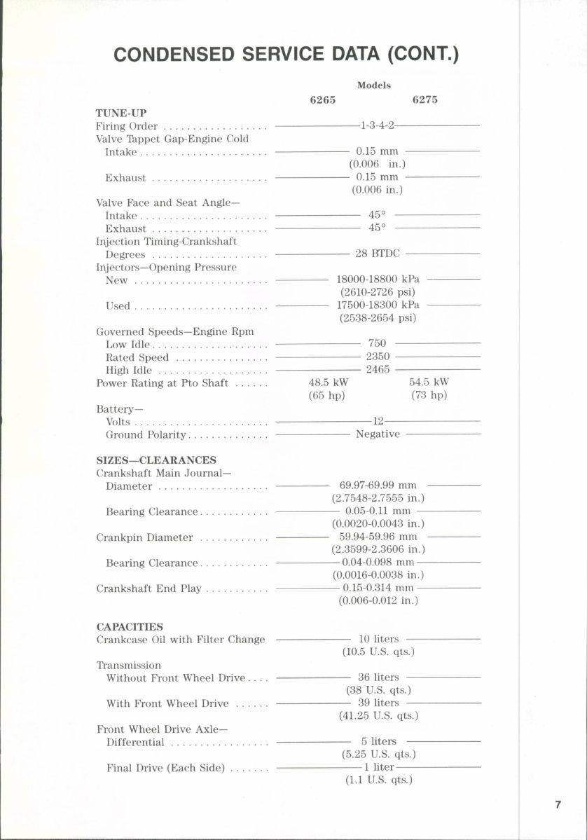
CONDENSED SERVICE DATA (CONT.) Models 6265 6275 TUNE UP Firing Order Valve Tappet Gap-Engine Cold Intake Exhaust Valve Face and Seat Angle- Intake Exhaust Injection Timing-Crankshaft Degrees Injectors—Opening Pressure New . Used Governed Speeds—Engine Rpm Low Idle Rated Speed High Idle Power Rating at Pto Shaft Battery- Volts Ground Polarity SIZES—CLEARANCES Crankshaft Main Journal- Diameter Bearing Clearance Crankpin Diameter Bearing Clearance Crankshaft End Play CAPACITIES Crankcase Oil with Filter Change Transmission Without Front Wheel Drive . . . . With Front Wheel Drive Front Wheel Drive Axle—- Differential Final Drive (Each Side) -1-3-4-2- - 0.15 mm - (0.006 in.) - 0.15 mm - (0.006 in.) 45° 45° 28 BTDC 18000-18800 kPa (2610-2726 psi) 17500-18300 kPa (2538-2654 psi) 750 2350 2465 48.5 kW (65 hp) 54.5 kW (73 hp) -12- Negative — 69.97-69.99 mm - (2.7548-2.7555 in.) — 0.05-0.11 mm — (0.0020-0.0043 in.) — 59.94-59.96 mm - (2.3599-2.3606 in.) — 0.04-0.098 mm — (0.0016-0.0038 in.) — 0.15-0.314 mm — (0.006-0.012 in.) 10 liters (10.5 U.S. qts.) 36 liters (38 U.S. qts.) — 39 liters — (41.25 U.S. qts.) 5 liters (5.25 U.S. qts.) 1 liter (1.1 U.S. qts.) www.classicmachinery.net
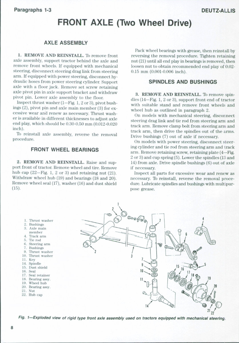
Paragraphs 1-3 DEUTZ-ALLIS FRONT AXLE (Two Wheel Drive) AXLE ASSEMBLY 1. REMOVE AND REINSTALL. To remove front axle assembly, support tractor behind the axle and remove front wheels. If equipped with mechanical steering, disconnect steering drag link from steering arm. If equipped with power steering, disconnect hy- draulic hoses from power steering cylinder. Support axle with a floor jack. Remove set screw retaining axle i)iv()t pin in axle support bracket and withdraw pivot pin. Lower axle assembly to the floor. Inspect thrust washer (1—Fig. 1, 2 or 3), pivot bush- ings (2), pivot pin and axle main member (3) for ex- cessive wear and renew as necessary. Thrust wash- er is available in different thicknesses to adjust axle end play, which should be 0.30-0.50 mm (0.012-0.020 inch). To reinstall axle assembly, reverse the removal procedure. FRONT WHEEL BEARINGS 2. REMOVE AND REINSTALL. Raise and sup port front of tractor. Remove wheel and tire. Remove hub cap (22-Fig. 1, 2 or 3) and retaining nut (21). Withdraw wheel hub (19) and bearings (18 and 20). Remove wheel seal (17), washer (16) and dust shield (15). Pack wheel bearings with grease, then reinstall by reversing the removal procedure. Tighten retaining nut (21) until all end play in bearings is removed, then loosen nut to obtain recommended end play of 0.02- 0.15 mm (0.001-0.006 inch). SPINDLES AND BUSHINGS 3. REMOVE AND REINSTALL. To remove spin- dles (14—Fig. 1, 2 or 3), support front end of tractor with suitable stand and remove front wheels and wheel hub as outlined in paragraph 2. On models with mechanical steering, disconnect steering drag link and tie rod from steering arn i and track arm. Remove clamp bolt from steering arm and track arm, then drive the spindles out of the arms. Drive bushings (7) out of axle if necessary. On models with power steering, disconnect steer- ing cylinder and tie rod from steering arm and i rack arm. Remove retaining screw, retaining plate (4--Fig. 2 or 3) and cup spring (5). Lower the spindles (II i and 14) from axle. Drive spindle bushings (6) out ol axle if necessary. Inspect all parts for excessive wear and renew as necessary. To reinstall, reverse the removal proce- dure. Lubricate spindles and bushings with mult [pur- pose grease. 1. 2. 3. 4. 5. 6. 7. 9. 10. 11. 14. 15. U). 17. 18. 19. 20. 21. 22. Thrust washer Bushings Axle main member Track arm Tie rod Steering arm Bushings Thrust washer Thrust washer Key Spindle Dust shield Seal Seal retainer Bearing assy. Wheel hub Ik^aring assy. Nut Hub cap Fig. I—Exploded view of rigid type front axle assembly used on tractors equipped with mechanical steering. www.classicmachinery.net
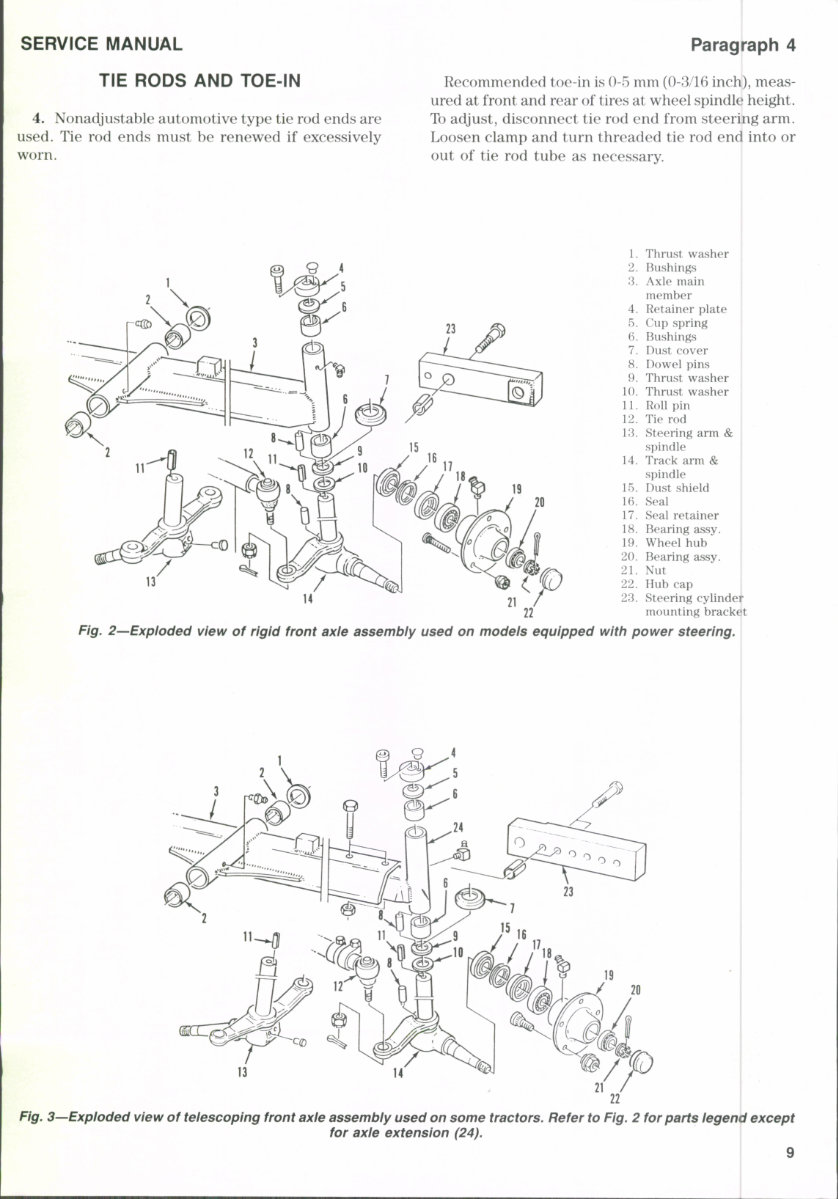
SERVICE MANUAL TIE RODS AND TOE-IN 4. Nonadjustable automotive type tie rod ends are used. Tie rod ends must be renewed if excessively worn. Paragraph 4 Recommended toe-in is 0-5 mm (0-3/16 inch), meas- ured at front and rear of tires at wheel spindle height. To adjust, disconnect tie rod end from steering arm. Loosen clamp and turn threaded tie rod end into or out of tie rod tube as necessary. 13 1. Thrust washer 2. Bushings 3. Axle main member 4. Retainer plate 5. Cup spring (>. Bushings 7. Dust cover 8. Dowel pins 9. Thrust washer 10. Thrust washer 11. Roll pin 12. Tie rod 13. Steering arm & spindle 14. Track arm & spindle 15. Dust shield 16. Seal 17. Seal retainer 18. Bearing assy. 19. Wheel hub 20. Bearing assy. 21. Nut 22. Hub cap 23. Steering cylinder mounting bracket Fig. 2—Exploded view of rigid front axle assembly used on modeis equipped with power steering. O 4 n Fig. 3—Expioded view of telescoping front axle assembly used on some tractors. Refer to Fig. 2 for parts legend except for axle extension (24). www.classicmachinery.net
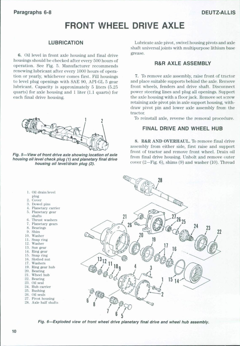
Paragraphs 6-8 DEUTZ-ALLIS FRONT WHEEL DRIVE AXLE LUBRICATION 6. Oil level in front axle housing and final drive housings should be checked after every 500 hours of operation. See Fig. 5. Manufacturer recommends renewing lubricant after every 1000 hours of opera- tion or yearly, whichever comes first. Fill housings to level plug openings with SAE 90, API-GL 5 gear lubricant. Capacity is approximately 5 liters (5.25 quarts) for axle housing and 1 liter (1.1 quarts) for each final drive housing. Fig. 5—View of front drive axle showing location of axle housing oii level check plug (1) and planetary final drive housing oil level/drain plug (2). Lubricate axle pivot, swivel housing pivots and axle shaft universal joints with multipurpose lithium base grease. R&R AXLE ASSEMBLY 7. To remove axle assembly, raise front of tractor and place suitable supports behind the axle. Remove front wheels, fenders and drive shaft. Disconnect power steering lines and plug all openings. Sujiport the axle housing with a floor jack. Remove set S'^rew retaining axle pivot pin in axle support housing, with- draw pivot pin and lower axle assembly froir the tractor To reinstall axle, reverse the removal procedure. FINAL DRIVE AND WHEEL HUB 8. R&R AND OVERHAUL. Tb remove final drive assembly from either side, first raise and support front of tractor and remove front wheel. Drain oil from final drive housing. Unbolt and remove cuter cover (2—Fig. 6), shims (9) and washer (10). Thread 1. Oil drain level plug 2. Cover 3. Dowel pins 4. Planetary carrier 5. Planetary gear shafts 6. Thrust washers 7. Planetary gears 8. Bearings 9. Shim 10. Washer 11. Snap ring 12. Washer 13. Sun gear 14. Ring gear 15. Snap ring 16. Slotted nut 17. Washers 19. Ring gear hub 20. Bearing 21. Wheel hub 22. Bearing 23. Oil seal 24. Hub carrier 25. Bushing 26. Oil seals 27. Pivot housing 28. Axle half shafts Fig. 6—Exploded view of front wheel drive planetary final drive and wheel hub assembly. 10 www.classicmachinery.net
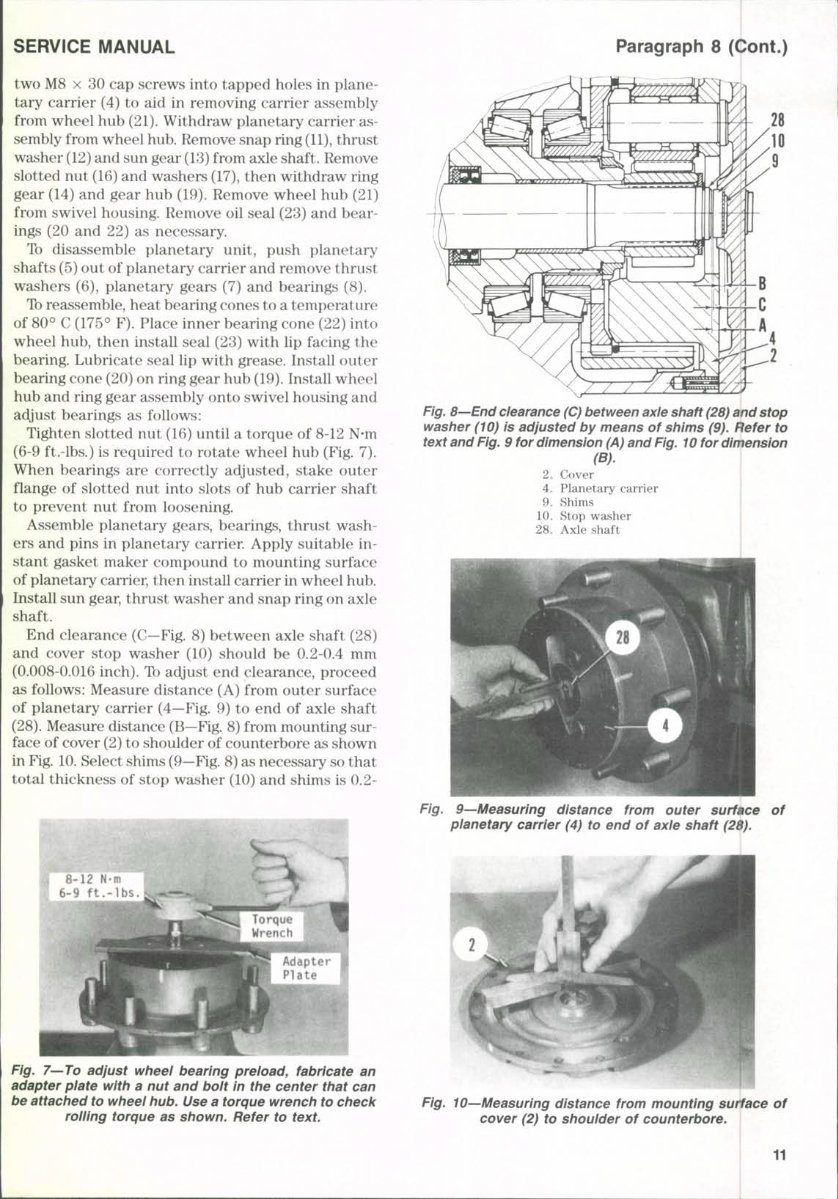
SERVICE MANUAL two M8 X 30 cap screws into tapped holes in plane- tary carrier (4) to aid in removing carrier assembly from wheel hub (21). Withdraw planetary carrier as- sembly from wheel hub. Remove snap ring (11), thrust washer (12) and sun gear (13) from axle shaft. Remove slotted nut (16) and washers (17), then withdraw ring gear (14) and gear hub (19). Remove wheel hub (21) from swivel housing. Remove oil seal (23) and bear- ings (20 and 22) as necessary. To disassemble planetary unit, push planetary shafts (5) out of planetary carrier and remove thrust washers (6), planetary gears (7) and bearings (8). To reassemble, heat bearing cones to a temperature of 80° C (175° F). Place inner bearing cone (22) into wheel hub, then install seal (23) with lip facing the bearing. Lubricate seal lip with grease. Install outer bearing cone (20) on ring gear hub (19). Install wheel hub and ring gear assembly onto swivel housing and adjust bearings as follows: Tighten slotted nut (16) until a torque of 8-12 N-m (6-9 ft.-lbs.) is required to rotate wheel hub (Fig. 7). When bearings are correctly adjusted, stake outer flange of slotted nut into slots of hub carrier shaft to prevent nut from loosening. Assemble planetary gears, bearings, thrust wash- ers and pins in planetary carrier. Apply suitable in- stant gasket maker compound to mounting surface of planetary carrier, then install carrier in wheel hub. Install sun gear, thrust washer and snap ring on axle shaft. End clearance (C—Fig. 8) between axle shaft (28) and cover stop washer (10) should be 0.2-0.4 mm (0.008-0.016 inch). To adjust end clearance, proceed as follows: Measure distance (A) from outer surface of planetary carrier (4—Fig. 9) to end of axle shaft (28). Measure distance (B—Fig. 8) from mounting sur- face of cover (2) to shoulder of counterbore as shown in Fig. 10. Select shims (9—Fig. 8) as necessary so that total thickness of stop washer (10) and shims is 0.2- Paragraph 8 (Cont.) 8-12 N-m 6-9 ft.-lbs. Fig. 7—To adjust wheei bearing preload, fabricate an adapter plate with a nut and bolt in the center that can be attached to wheel hub. Use a torque wrench to check rolling torque as shown. Refer to text. Fig. 8—End clearance (C) between axle shaft (28) and stop washer (10) is adjusted by means of shims (9). Refer to text and Fig. 9 for dimension (A) and Fig. 10 for dimension 2. Cover 4. Planetary carrier 9. Shims 10. Stop washer 28. Axle shaft Fig. 9^Measuring distance from outer surface of planetary carrier (4) to end of axle shaft (28). Fig. 10—Measuring distance from mounting surface of cover (2) to shoulder of counterbore. 11 www.classicmachinery.net
This comprehensive shop manual for the Deutz Allis 6265 tractor provides detailed instructions for maintenance and servicing, complete with diagrams and manufacturer specifications.
Instant access - no waiting
Language: English
Format: PDF
Compatibility: All Versions of Windows, Mac, iOS, BB, Android, etc
Bookmarked, indexed, searchable
Topics covered in this manual include:
Brakes
Cab
Clutch
Cooling System
Diesel Fuel System
Differential
Electrical System
Engine
Final Drive
Front Axle (Two-Wheel-Drive)
Front Wheel Drive Axle
Hydraulic System
Main Drive
Manual Steering
Power Steering
Power Take-Off
Rear Axle
Transmission
Maintenance
And much more...
This manual is in PDF format, allowing for easy viewing, zooming, and printing on any computer. It contains detailed illustrations, exploded diagrams, drawings, and photos to guide you through the service repair procedures, along with technical details and step-by-step instructions.
For optimal viewing, the document may require the latest version of Acrobat Reader. If you encounter any issues, please ensure you have the most recent version of Adobe Acrobat Reader installed.
For any other manuals you may need, feel free to email for further assistance.