

David Brown 885 Tractor Service & Repair Manual
What's Included?
Fast Download Speeds
Online & Offline Access
Access PDF Contents & Bookmarks
Full Search Facility
Print one or all pages of your manual

dl CASE
BROWN)
MODELS: 885·885N·995-1210·1212·141o.1412
INDEX (By Starting Paragraph)
BELT PULLEY ....................... • .........
BRAKES, WHEEL ............................ ..
CLUTCH:
Adjustment., ..... " ...... ". 0' ••••••••••••••••
Remove & Reinstall . ...... > , •• , ••••••••••••••••
Overhaul . .... , . > ••••••• > •••• < ••••••••••••••••
COOLING SYSTEM:
Radiator ............... , ..... ,., ..... , ... , ... .
Thermostat . ..... " ...... , .................... .
Water Pump . ............ " . > •••••••••••••••••
DIESEL FUEL SYSTEM:
Bleeding Fuel System ......................... .
Filters . ........... , ... , ., .. 0 ••••••••••••••••••
Injection Pump ............................... .
Injector Nozzles. .. ., .. 0 , • ' ••• , • , ••••••••••••
Troubleshooting ............................. .
DIFFERENTIAL:
Adjust ...................................... .
Lock ........................................ .
Overhaul. ................................... .
Remove & Reinstall. > ••••• , " •••• , ••••••••••••••
ELECTRICAL SYSTEM:
Alternator . .... , ...... , ... , , .... , ............ .
Starting Motor .......................... .
ENGINE:
Assemhly. R&R ......................... .
Cam Followers . .. " ........ ", .... " ....... , ..... .
Camshaft .................................... .
Connecting Rod Bearings . ..................... .
Crankshaft & Bearings ........................ .
Crankshaft Oil Seals ...................... '" ..
Cylinder Head ................................ .
Cylinders .................................... .
Flywheel. R&R ............................... .
Main Bearings ................................ .
Oil Pan ...................................... .
Oil Pump .................................... .
Piatons & Rings .............................. .
Piston & Rod Removal. ....................... .
Piston Pins . ....... _ . . .. . ... _ ............... .
Rocker Arms ................................. .
Timing Gear Cover ..... , ....... , ............. .
Timing Gears ......................... " ... " .. .
Turbocharger . ............................ " .. .
Valve Adjustment ............................ .
Valve. Guides & Seats ........................ .
Valve Springs ................................ .
885
225
215
143
146
150
128
130
131
103
102
110
120
94
201
205
204
200
132
140
57
76
77
82
85
87
63
84
93
85
92
90
83
80
81
65
71
73
66
66
70
995
225
215
144
146
150
128
130
131
104
102
113
120
94
201
205
204
200
132
140
59
76
78
82
86
87
63
84
93
86
92
90
63
80
81
65
72
74
67
68
70
1210,
1212
225
216
145
147
152.153
129
130
131
105
102
115
120
94
201.202
205
204
200
132
140
61
76
78
82
86
87
63
84
93
86
92
90
83
80
81
65
72
74
67
68
70
1410,
1412
225
216
145
148
153
129
130
131
105
102
115
120
94
201.202
205
204
200
132
140
61
76
78
82
86
87
63
84
93
86
92
90
83
80
81
65
72
74
93A
67
68
70
INDEX (Cont.)
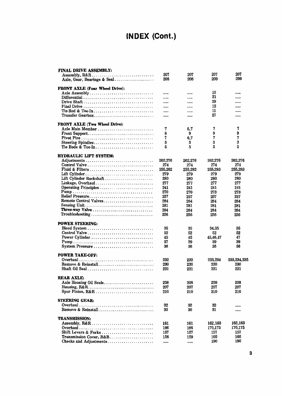
FINAL DRIVE ASSEMBLY:
Assembly, R&R .............. . . . . . .. , ......... 207 207 207 207
Axle. Gear, Bearings & Seal .................... 208 208 209 209
FRONT AXLE (Four Wheel Drive):
Axle Assembly ................................ 10
Differential ...................................
21
Drive Shaft ................................... 29
Final Drive . .................... , ... , ......... 12
Tie-Rod & Toe·In .............................. 11
Transfer Gearbox . .... , ... , .... , ............. ' 27
FRONT AXLE (Two Wheel Drive):
Axle Main Member ............................ 7 6,7 7 7
Front Support ................................. 8 9 9 9
Pivot Pins .. , ................. , ... , .......... , 7 6,7 7 7
Steering Spindles . .. , .......................... 3 3 3 3
Tie Rods & Toe-In .................... ........ , 5 5 5 5
HYDRAULIC LIFT SYSTEM:
Adjustments .................................. 262,276 262,276 262,276 262,276
Control Valve ................................. 274 274 274 274
Fluid & Filters ................................ 255,282 255,282 255,283 255,283
Lift Cylinder .................................. 279 279 279 279
Lift Cylinder Rockshaft ........................ 280 280 280 280
Linkage, Overhaul ............................. 277 277 277 277
Operating Principles . ...... , ........ , ........ , . 241 241 241 241
Pump ........................................ 270 270 273 273
Relief Pressure . . , .................... < ••••••••• 257 257 257 257
Remote Control Valves . ........................ 284 284 284 284
Sensing Unit .................................. 281 281 281 281
Three-way Valve .............................. 284 284 284 284
Troubleshooting ............................... 256 256 256 256
POWER STEERING:
Bleed System ................................. 35 35 34,35 35
Control Valve . ..... , ............. , .. 0 ••••• , •• , 52 52 52 52
Power Cylinder . .............................. 45 45 45,46.47 47
Pump ........................................ 37 39 39 39
System Pressure . ................ , . , ...... " ... 36 36 36 36
POWER TAKE-OFF:
Overhaul ..................................... 282 232 233,284 283,234,285
Remove & Reinstall . ........................... 230 230 230 280
Shaft Oil Seal ................................. 231 231 231 231
REAR AXLE:
Axle Housing Oil Seals ......................... 203 208 209 209
Housing, R&R ................................. 207 207 207 207
Spur Pinion, R&R ............. 0 ••••••••••••••• 210 210 210 210
STEERING GEAR:
Overhaul . .............................. , ..... 32 32 32
Remove & Reinstall. ........................... 30 30 31
TRANSMISSION:
Assembly, R&R ............................... 161 161 162,183 162,163
Overhaul ..................................... 166 166 170,175 170,175
Shift Levers & Forks .......................... 157 157 157 157
Transmission Cover. R&R .. .................... 158 159 160 160
Checks and Adjustments ....................... 190 190
3
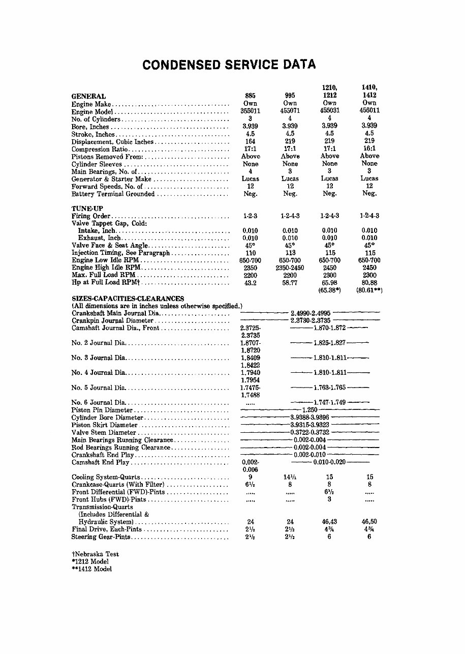
CONDENSED SERVICE DATA
GENERAL
Engine Make .................................. ..
Engine Model. ................................. .
No. of Cylinders .......................... .
Bore, Inches ................................... .
Stroke. Inches .. ... , ............................ .
Displacement. Cubic Inches . ..................... .
Compression Ratio . ................. , ..... , . , ... .
Pistons Removed From: . . . . . . . . . . . . . .. . ........ .
Cylinder Sleeves ............................... .
Main Bearings, No. of . .......................... .
Generator & Starter Make . ......... , ........... .
Forward Speeds, No. of ......................... .
Battery Terminal Grounded. , ............... , ... ,
TUNE-UP
Firing Order ................................... .
Valve Tappet Gap, Cold:
Intake, Inch ................................. ..
Exhaust, Inch ......... ' ...................... .
Valve Face & Seat Angle ....................... ..
Injection Timing, See Paragraph ................. .
Engine Low Idle RPM .......................... .
Engine High Idle RPM .......................... .
Max. Full Load RPM ........................... .
Hp at Full Load RPMt ......................... ..
SIZES-CAPACITIES·CLEARANCES
885
Own
355011
3
3.939
4.5
164
17:1
Above
None
4
Lucas
12
Neg.
1·2-3
0.010
0.010
45·
110
650·700
2350
2200
43.2
995
Own
455071
4
3.939
4.5
219
17:1
Above
None
3
Lucas
12
Neg.
1-2·4-3
0.010
0.010
45·
113
650·700
2350·2450
2200
58.77
1210,
1212
Own
455031
4
3.939
4.5
219
17:1
Above
None
3
Lucas
12
Neg.
1·2·4·3
0.010
0.010
45·
115
650·700
2450
2300
65.98
(65.38*)
1410,
1412
Own
455011
4
3.939
4.5
219
16:1
Above
None
3
Lucas
12
Neg.
1·2·4·3
0.010
0.010
45·
115
650·700
2450
2300
80.88
(80.61'*)
(All dimensions are in inches unless otherwise specified.)
Crankshaft Main Journal Dia ................... ... ------2.4990·2.4995 ------
Crankpin Journal Diameter ........... " . . ... . .. . . 2.3730·2.3735 -----
Camshaft Journal Dia., Front ........... .......... 2.3725· ---1.870·1.872--
No.2 Journal Dia . ..... , ........ , .... , ...... .
No.3 Journal Dia ............................... .
No.4 Journal Dia ............................... .
No. 5 Journal Dia .. .... , ....................... _ ,
No.6 Journal Dia .. ... _ ................. _
Piston Pin Diameter .......... ... ' . , ....... , . _ .. .
Cylinder Bore Diameter .. ....................... .
Piston Skirt Diameter _ ...................... .
Valve Stem Diameter . ................. , ........ .
Main Bearings Running Clearance . ...... , .. .
Rod Bearings Running Clearance . ................ ,
Crankshaft End Play ............................ .
Camshaft End Play ............................ ..
Cooling System-Quarts . ......................... .
Crankcase-Quarts (With Filter) .................. .
Front Differential (FWD)·Pints .................. .
Front Hubs (FWD)·Pints .... '" ......... " ...... .
Transmission-Quarts
(Includes Differential &
Hydraulic System) ............................ .
Final Drive, Each-Pints . ........................ .
Steering Gear· Pints ....................... .
tNebraska Test
'1212 Model
**1412 Model
2.3735
1.8707· --1.825-1.827--
1.8720
1.8409
1.8422
1.7940
1.7954
1.7475-
1.7488
--1.810·1.811--
--1.810·1.811--
--1.763·1.765--
--1.747·1.749--
------1.250
-----3.93883.9396 -----
-----:3.9315-3.9323 -----
-----10.3722-0.3732 -----
-----0.002·0.004-----
=====0.002-0.004-----
0.002·0.010 -----
-- 0.010·0.020-- 0.002·
0.006
9
6
1
1z
46,43
4'1<
6
15
8
885-995-1210-1212-1410-1412
Paragraphs 1-4
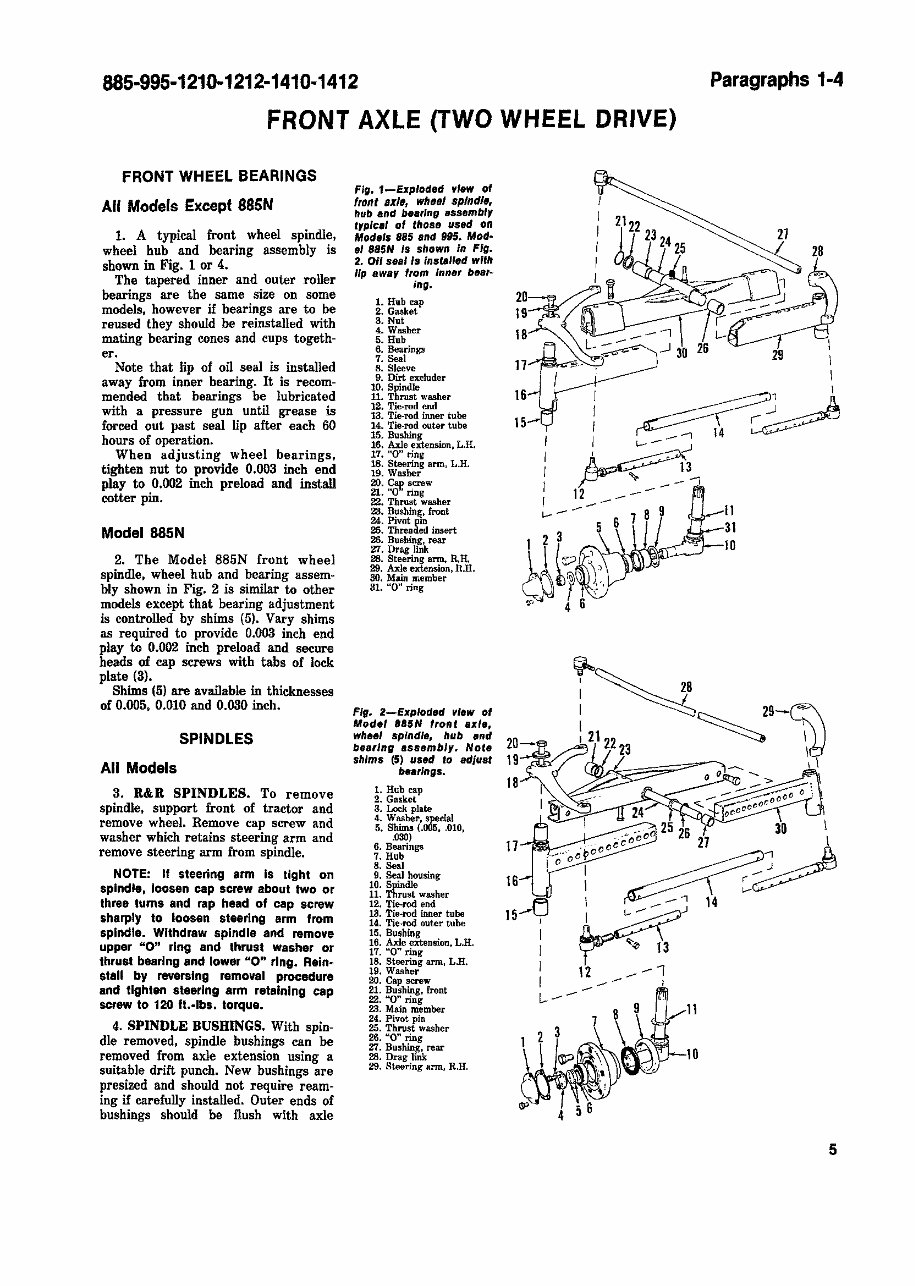
FRONT AXLE (TWO WHEEL DRIVE)
FRONT WHEEL BEARINGS
All Models Except 88SN
1. A typical front wheel spindle,
wheel hub and bearing assembly is
shown in Fig. 1 or 4.
The tapered inner and outer roller
bearings are the same size on some
models. however if bearings are to be
reused they should be reinstalled with
mating bearing cones and cups togeth-
er.
Note that lip of oil seal is installed
away from inner bearing. It is recom-
mended that bearings be lubricated
with a pressure gun until grease is
forced out past seal lip after each 60
hours of operation.
When adjusting wheel bearings.
tighten nut to provide 0.003 inch end
play to 0.002 inch preload and install
cotter pin.
Model8S5N
2. The Model 885N front wheel
spindle. wheel hub and bearing assem-
bly shown in Fig. 2 is similar to other
models except that bearing adjustment
is controlled by shims (5). Vary shims
as required to provide 0.003 inch end
play to 0.002 inch preload and secore
heads of cap screws with tabs of leek
plate (3).
Shims (5) are available in thicknesses
of 0.005, 0.010 and 0.030 inch.
SPINDLES
All Models
3. R&R SPINDLES. To remove
spindle. support front of tractor and
remove wheel. Remove cap screw and
washer which retains steering arm and
remove steering arm from spindle.
NOTE: If steering arm Is tight on
spindle, loosen cap screw about two or
three turns and rap head of cap screw
sharply to loosen steering arm from
spindle. Withdraw spindle and remove
upper "0" ring and thrust washer or
thrust bearing and lower "0" ring. Reinm
stall by reversing removal procedure
and tighten steering arm retaining cap
screw to 120 ft.-Ibs. torque.
4. SPINDLE BUSIIINGS. With spin-
dle removed, spindle bushings can be
removed from axle extension using a
suitable drift punch. New bushings are
presized and should not require ream-
ing if carefully installed. Outer ends of
bushings should be flush with axle
Fig. 1-Exploded ,"lew of
front axlll wheel spIn dis.
hub and bearing assembl,
typlca' of those used on
Models 885 and 995. Mod·
e' ,85H 'S shown In Fig.
2. Oil sea' Is installed with
lip away from Inner blte,-
ing.
1. Hub cap
2. Gasket
3. Nut
4. Washer
5. Hub
6. Bearingll
7. Seal
8. Sleeve
9. Dirt excluder
i~: ~h:~ washer
12. Tie·rod end
13. Tie·rod inner tube
14. Tie·rod outer tube
15. Bushing
16. Axle extension, L.R.
17. "0" ring
18. Steering ann, L.H.
19. Washer
20. ~ screw
21. "'0' ring
22. Thrust washer
23. Bushin~. front
~: ~v:!S!d insert
26. Busbing, rear
Zl. Drag link
28. Steering arm, R.R.
29. Axle enension. R.H.
30. Main member
31. "0" ring
Fig. 2-Exploded vIew of
Model ,aSH 'ront axle,
WhH' spindle, hub end
bea"ng assembly. Note
shims (5) used to adjust
beallngs.
1. Hub cap
2. Gasket
3. Lock plate
4. Washer. special
5. Shima (.005, .010,
.030)
6. Bearings
7. Hub
8. Sea]
9. Seal housing
10. Spindle
11. Thrust washer
12. Tie-rod end
13. Tie-rod inner tube
14. Tie·rod outer tube
15. Bushing
16. Axle extension, L.R.
17. "0" ring
18. Steering arm, LB.
19. Washer
20. Cap screw
21. Bushing, front
22. "'0" ring
23. Main member
24. Pivot pin
25. Thrust washer
26. ''0'' ring
27. Bushing, rear
28. Drag link
29. Steering arm, R.H.
I
I 2122
I J.J 23
24
I 25
I I
20~1~
19
18 _-"'
L-:-=- ..J 30
17 - ~- ,
21
29
I
I
I
16
15
I
~' I
I ~4 =:~
I I c.---
, ~
I
I
I
I
~~ 13
IF ,. ---"'
c.---
6
789 11
5 31
1 2 3 ~~~::::'J-IO
~~l~~.
~. 4 6
20
19-"'''/
18
I . " . 25 26 30 I
(:-;0
00
' 27 \
::ooro~~
IV? l~J 14
I r-"" 1'3
I 12 _-1
I _ ,
l----
8 9 11
7
1 2 3
<lP 4 56
5
Paragraphs 5-6
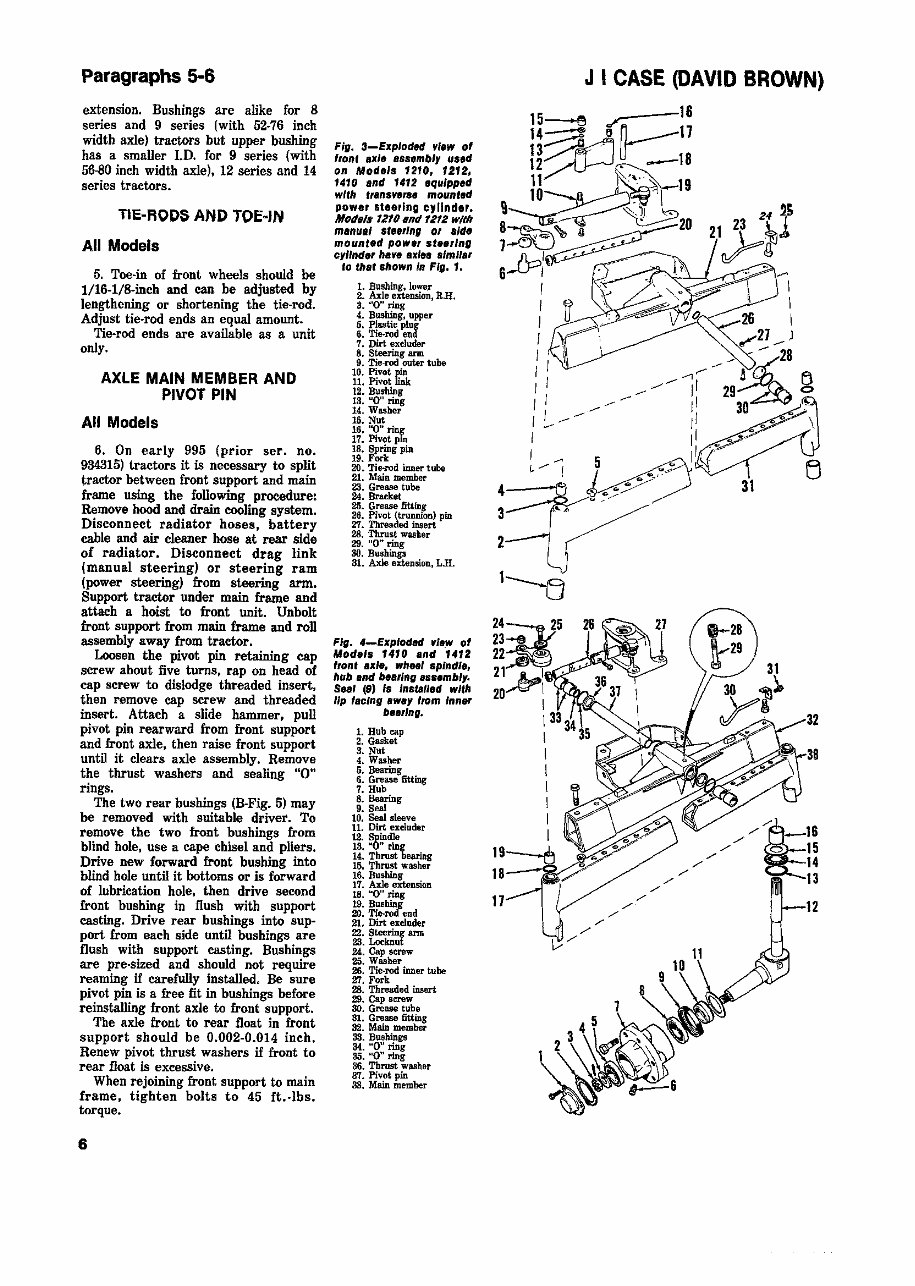
extension. Bushings are alike for 8
series and 9 series (with 52·76 inch
width axle) tractors but upper bushing
has a smaller I.D. for 9 series (with
56-80 inch width axle), 12 series and 14
series tractors.
TIE-RODS AND TOE-IN
All Models
5. Toe-in of front wheels should be
l/16-l/S-inch and can be adjusted by
lengthening or shortening the tie-rod.
Adjust tie-rod ends an equal amount.
Tie-rod ends are available as a unit
only.
AXLE MAIN MEMBER AND
PIVOT PIN
All Models
6. On early 995 (prior ser. no.
934315) \.ractors it is necessary to split
tractor between front support and main
frame using the following procedure:
Remove hood and drain cooling system.
Disconnect radiator hoses. battery
cable and air cleaner hose at rear side
of radiator. Disconnect drag link
(manual steering) or steering ram
(power steering) from steering arm.
Support traetor under main frame and
attach a hoist to Iront unit. Unbolt
Iront support Irom main frame and roll
assembly away from tractor.
Loosen the pivot pin retaining cap
screw about five turns, rap on head of
cap screw to dislodge threaded insert,
then remove cap screw and threaded
insert. Attach a slide hammer, pull
pivot pin rearward from front support
and front axle. then raise front support
until it clears axle assembly. Remove
the thrust washers and sealing "0"
rings.
The two rear bushings (B-Fig. 5) may
be removed with suitable driver. To
remove the two front bushings from
blind hole. use a cape chisel and pliers.
Drive new forward front bushing into
blind hole until it bottoms or is forward
of lubrication hole. then drive second
front bushing in flush with support
casting. Drive rear bushings into sup·
port from each side until bushings are
flush with support casting. Bushings
are pre·sized and should not require
reaming if carefully installed. Be sure
pivot pin is a free fit in bushings before
reinstalling front axle to front support.
The axle front to rear float in front
support should be 0.002-0.014 inch.
Renew pivot thrust washers if front to
rear float is excessive.
When rejoining front support to main
frame, tighten bolts to 45 ft.-lbs.
torque.
6
Fig. 3-Exploded ~,.w of
front Ix'e 8ssemb'y used
on Models 1210. 1212,
1410 and 1412 equipped
with transverse mounted
powe, Iteerlng cylinder.
Mqd.'9 1210 and 1212 with
manua' st •• rlng 01 .,de
mounted powel steelInG
cylinder ha~e alde• • Imllar
10 that shown In FIG. 1.
1. Bushing, lower
2. Axle extension, RH.
a. "0" ring
4.. Bushing, upper
6. Plastic plug
6. Tie-rod end
7. Dirt excluder
8. Steering ann
9. Tie-.rod outer tube
10. Pivot pin
11. Pivot link
12. Bushing
13. uO" ring
14.. Washer
15. Nut
16. "0" ~
17. Pivot pm
18. ~ring pin
19. Fork
20. Tie-rod inner tube
21. Main member
23. Grease tube
24. Bracket
25. Grease fitting
26. Pivot (trunnion) pin
27. Threaded insert
28. Thrust washer
29. "0" ring
30. Bushings
31. Axle extension, LlI.
Fig. 4-Exploded ~I._w of
Models 1410 and 1412
fronfaxle, wheel spindle,
hub and bearing assembly.
Sea' (9) #s Insfalled with
lip 'acIng awey 110m Inner
be.,lng.
1. Hub cap
2. Gasket
3. Nut
4. Washer
5. Bearing
6. Grease fitting
7. Hub
8. Bearing
9. Seal
10. Seal sleeve
11. Dirt excluder
12. Spindle
13. "0" rin
14.. Thrust tearing
15, Thrust washer
16. Bushing
17. Axle extension
18. "0" ring
19. B~hin.
20. Tie-rod end
21. Dirt excluder
22. Steering ann
23. Loeimut
24.. Cap serew
25. Washer
26. Tie-rod inner tube
2:1. Fork
28. Threaded insert
29. Cap serew
SO. Grease tube
81. Grease fitting
32. Main member
38. Bushings
34. "0" ring
35. "0" ring
36. Thrust washer
37. Pivot pin
as. Main member
\//'
J I CASE (DAVID BROWN)
/'
/'
,/
/'
/'
/'
/'
/'
/'
/'
/'
/'
32
38
/'
885-995-1210-1212-1410-1412
Paragraphs 7-12
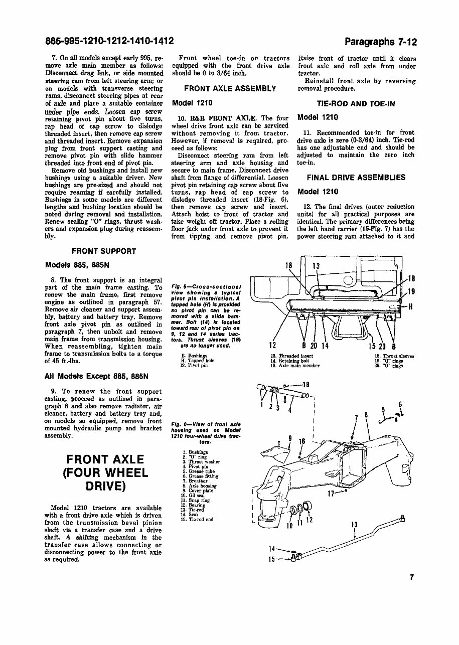
7. On alI models except early 995, reo
move axle main member as follows:
Disconnect drag link, or side mounted
steering ram from left steering arm; or
on models with transverse steering
rams, disconnect steering pipes at rear
of axle and place a suitable container
under pipe ends. Loosen cap screw
retaining pivot pin about five turns.
rap head of cap screw to dislodge
threaded insert, then remove cap screw
and threaded insert. Remove expansion
plug from front support casting and
remove pivot pin with slide hammer
threaded into front end of pivot pin.
Remove old bushings and install new
bushings using a suitable driver. New
bushings are pre-sized and should not
require reaming if carefully installed.
Bushings in some models are different
lengths and bushing location should be
noted during removal and installation.
Renew sealing "0" rings. thrust wash-
ers and expansion plug during reassem-
bly.
FRONT SUPPORT
Models 885, 88SN
8. The front support is an integral
part of the main frame casting. To
renew the main frame. first remove
engine as outlined in paragraph 57.
Remove air cleaner and support assem·
bly, battery and battery tray. Remove
front axle pivot pin as outlined in
paragraph 7. then unbolt and remove
main frame from transmission housing.
When reassembling. tighten main
frame to transmission bolts to a torque
of 45 ft.-lbs.
All Models Except 885, 88SN
9. To renew the front support
casting. proceed as outlined in para·
graph 6 and also remove radiator. air
cleaner, battery and battery tray and,
on models so equipped. remove front
mounted hydraulic pump and bracket
assembly.
FRONT AXLE
(FOUR WHEEL
DRIVE)
Model 1210 tractors are available
with a front drive axle which is driven
from the transmission bevel pinion
shaft via a transfer case and a drive
shaft. A shifting mechanism in the
transfer ease allows connecting or
disconnecting power to the front axle
as required.
Front wheel toe·in on tractors
equipped with the front drive axle
should be 0 to 3/64 inch.
FRONT AXLE ASSEMBLY
Model 1210
10. R&R FRONT AXLE. The four
wheel drive front axle can be serv.iced
without removing it from tractor.
However. if removal is required. pro-
ceed as follows:
Disconnect steering ram from left
steering arm and axle housing and
secure to main frame. DisConnect drive
shaft from flange of differential. Loosen
pivot pin retaining cap screw about five
turns, rap head of cap screw to
dislodge threaded insert (lB-Fig. 6),
then remove cap screw and insert.
Attach hoist to front of tractor and
take weight off tractor. Place a rolling
floor jack under front axie to prevent it
from tipping and remove pivot pin.
Fig.5-Crossa$ectional
If/ew showing e typlca'
pivot pin Installation. A
tapped hole (H) is prodded
so pivot pin can be re--
moved with a slide ham-
mer. Bolt (14) Is located
toward rear of pivot pin on
9, 12 and 14 series trac-
tors. Thrust sleeves (18)
al'8 no longer used.
18
Raise front of tractor until it clears
front axle and roll axle from under
tractor.
Reinstall front axle by reversing
removal procedure.
TIE-ROD AND TOE-IN
Model 1210
11. Recommended toe-in for front
drive axle is zero (0·3/64) inch. Tie·rod
has one adjustable end and should be
adjusted to maintain the zero inch
toe-in.
FINAL DRIVE ASSEMBLIES
Model 1210
12. The final drives (outer reduction
units) for all practical purposes are
identical. The primary differences being
the left hand carrier (1S-Fig. 7) has the
power steering ram attached to it and
13
o - 18
19
H
B 20 14
15 20 B
B. Bushings 13. Threaded insert 18. Thrust sleeves
H. Tapped hole
12. Pivot pin
Fill. 6-View at front ax'e
housing used on Model
1210 four-wheel drive t,..c~
tors.
1. Bushings
2. "0" ring
3. Thrust washer
4. Pivot pin
5. Grease tube
6. Grease fitting
7. Breather
8. Axle housing
9. Cover plate
10. Oil seal
11. Snap ring
~:~e~l
14. Seal
15. Tie-rod end
14. Retaining bolt
15. Axle main member
14---..
15
19. ~O" rings
20. "0" rings
7
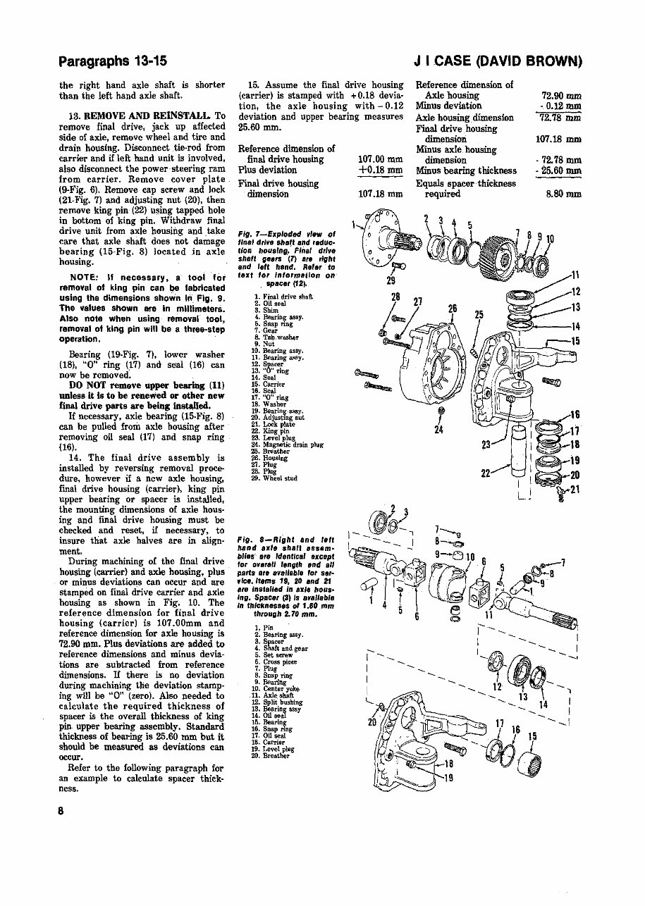
Paragraphs 13·15
the right hand axle shaft is shorter
than the left hand axle shaft.
13. REMOVE AND REINSTALL. To
remOVe final drive, jack up affected
side of axle, remove wheel and tire and
drain housing. Disconnect tie·rod from
carrier and if left band unit is involved.
also disconnect the power' steering ram
from carrier. Remove cover plate
(9-Fig. 6). Remove cap screw and lock
(21.Fig. 7) and adjusting nut (20), then
remove king pin (22) using tapped hole
in bottom of king pin. Withdraw final
drive, unit from axle housing and take
care that axle shaft does not damage
bearing (15·Fig. 8) located in axle
housing.
NOTE: If necessary. s- tool for
removal at king pin can I)e fabricated
using the dimensions shown in, Fig. 9.
The values shown are in millimeters.
Also note when using removar tool,
removal of king pin will be a three-step
operation.
Bearing (19-Fig. 7), lower washer
(18), "0" ring (17) and seal (16) can
now be removed.
DO NOT remove upper beariDg (11)
unless it is to be renewed or other new
!inal drive parts are being insWIed.
If necessary, axle hearing (15·Fig. 8)
can be pulled from axle housing after
removing oil seal (17) and snap ring
(16).
14. The final drive assembly is
installed by reversing removal proce·
dure. however if a new axle housing.
final drive housing (carrier), king pin
upper bearing or spacer is installed,
the mounting dimensions of axle hOlls·
ing and final drive honsing must be
ehecked and reset, if necessary. to
insure that axle halves are in align·
ment.
During machining of the final drive
housing (carrier) and axle housing, plus
or minus deviations can occQr and are
stamped on final drive carrier and axle
housing as shown in Fig. 10. The
reference dimension for final drive
housing (carrier) is 107.00mm and
reference dimension for axle housing is
72.90 mm. Plus deviations are added to
reference dimensions and minus devia-
tions are subtracted from reference
dimensions. If there is no deviation
during machining the deviation stamp·
ing will be "0" (zero). Also needed to
calculate the required thickness of
spacer is the overall thickness of king
pin upper bearing assembly. Standard
thickness of bearing is 25.60 mm but it
should he measured as deviations can
occur.
Refer to the following paragraph for
an example to calculate spacer thick-
ness.
8
15. Assume the final drive housing
(carrier) is stamped with + 0.18 devia-
tiOD, the axle housing with - 0.12
deviation and upper bearing measures
25.60 mm.
Reference dimension of
final drive housing
Plus deviation
Final drive housing
dimension
Fig. 7-Exploded view of
"nal drIve shatt and reduc·
lion housIng,' Final drive
shefl gears (7) are right
and leff hand. Re'.r to
text for Information on
spacer (12),
1. Final drive shaft
2. Oil seal
S. Shim
4. BelLrin~ aslIy.
5. Snap rmg
7. Gear
8. Tab, washer
9. Nut
10. Bearing assy.
11. Bejl,ring assy.
12. Spacer
13. "0" ring
14. Seal
15. Carrier
16. Seal
17. "0" ring
18. Washer
111. Bearln~-assy.
20. Adjusting nut
21. Lock plate
22. King pin
23. Level plug
24. Magnetic drain plug
25. Breather
26. Housing
21. Plug
28. Plug
29. Wheel stud
Fig. a-Right and letl
hand axle shari Bss.m~
bliss' Ite Identical except
for 0'l8,all length and all
parts are avallabl, 'or ser-
"le •• Itams 19, 20 end 2f
ere fnstalled In axle hous-
Ing. Spacer (3) Is available
In thlckness.s 01 1.60 mm
through 2. 70 mm.
1. Pin
2. Bearing assy.
3. Spacer
4. Shaft and gear
5. Set screw
6. Cross piece
7. Plug
8. Snap ring
9. Bearing
10. Center yoke
11. Axle slWt
12. Split bushing
13. Bearing assy
14. Oil seal
15. Bearin$
16. Snap nng
17. Oil seal
18. Carrier
19. Level plug
20. Breather
107.00 mm
+0.18mm
107.18 mm
J I CASE (DAVID BROWN)
Reference dimension of
Axle housing
Minus deviation
Axle housing dimension
Final drive housing
dimension
Minus axle housing
dimension
Minus hearing thickness
Equals spacer thickness
required
72.90mm
·O.12mm
72.78 mm
107.18 mm
. 72.78mm
·25.60 mm
8.80mm
g
16
I ~ 17
I ~ 18
1~19
1~20
U t'21
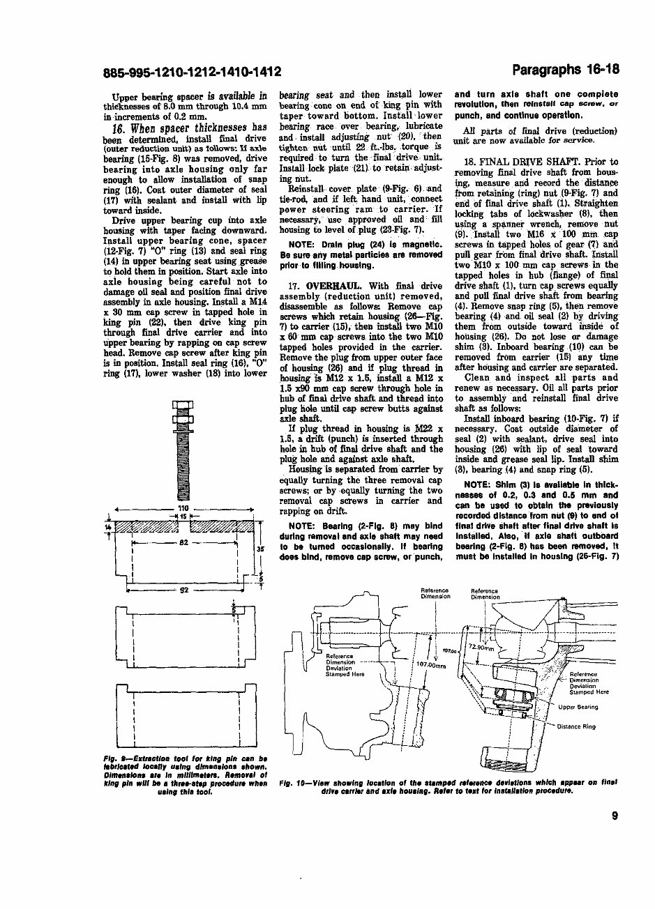
paragraph$ 19-20
ptlor 10 Inslalllng linal drive shalt gear
(7).
Position final drive shaft with wheel
studs down and block under shaft so
wheel studs are not touching. Place
housing (26). over final drive shaft.
Heat.gear (7) to about 100 degrees F,.
start gear on. splines of final drive
shalt. then press or drive. gear and
housing on final drive shaft. Install
loekwasher (8) and nut (9) and tighten
nut securely. Distance from nut to end
of shaft should he the same as that
recorded prior to disassembly. ,about 3
mm (l/8'in.) of final drive shaft thread
should be, exposed with nut tightened.
Retain nut by bending tabs of lock·
washer __ into slots in nut and gear~
. Refer to paragraph 20 for informa·
tion to join housing to carrier.
19. AXLE SHAFT. To remove axle
shaft from carrier, support. carrier and
axle -shaft a_nd drive bearing co,:te
(l,S-Fig. 8)· into carrier far enough to
allow removal of split bushing (12). Use
a soft faced hammer and drive axle
shaft out of hearing and carrier. Seal
(14) and he'l'"ing cup (13) can now be
removed from carrier. Outboard bear
c
ing assembly (2) cannot be removed
unless final drive shaft gear (7-Fig.7)
has heen removed. Spacer (3) should
have been retrieved when housing and
Carrier were separa~
NOTE: Tho axle universal Jolnl can
be ellsalsembled 8& 'oIlOVlS: Remove
snap rings (8·Flg. 8) and pull needle
bearings (9). Tip cro •• plocas (6) oul 01
center yoke (10), remove sa' screws (5),
then remove pins (1) and sallarate axle
halves from cross pieces.
It 135 ---- .... ,
I :- 70------l
fl,. 11-A "old'", cl.mp ca_" N """",.
loc.,,,·to- p~ .. ltt-.x_" ,moqm.iU dUrI"• ...
, .""bl,. Dlm.ii.'on• • r. In mUllm.r.,..
1,0
Clean and inspect all parts and
renew as necessary. Install axle shaft
in carrier as follows: Coat outside
diameter of seal 114) with sealant and
install in carrier (18) with lip toward
inside. Gre ... lip of seal. DriVe hearing
C1;lP into carrier with taper faCing in,
then insert gear end of axle through oil
seal and bearing cup. Hold axle
in- position and drive bearing cone on
axle shaft until the split bushing can be
installed with flat side up. Use a soft
faced hammer and bump end of axle
shaft until axle shaft gear seats on split
bushing.
NOTE:Ca .. should ba token alter
axle -Is Installed to prevent damage to
011 seal (14·Flg. 8) by movement 01 oxle
shaft during subsequent assembly. Use
of a clamp, shown In Fig. 11. is
recommended by the manufacturer and
ciampi. Inatollod bslweon carrier and
universal Jolnl. Clamp muat bo labrl·
caled locally and noto that dimensions
are In'mlilimelers.
20. ASSEMBLY. Before joining car-
rier (l8'Fig. 8) and housing (26-Fig. 7)
the preload for axle shaft must he
determined. The axle operates with a
0.25 mm preload and preload is con·
trolled by spacer (S-Fig. 8). Spacer is
available in thicknesses from 1.60 mm
through 2.70 mm in increments of 0.05
mID.
Determine correct spacer thi~ess
as follows:
1~ Measure from inner race of bear·
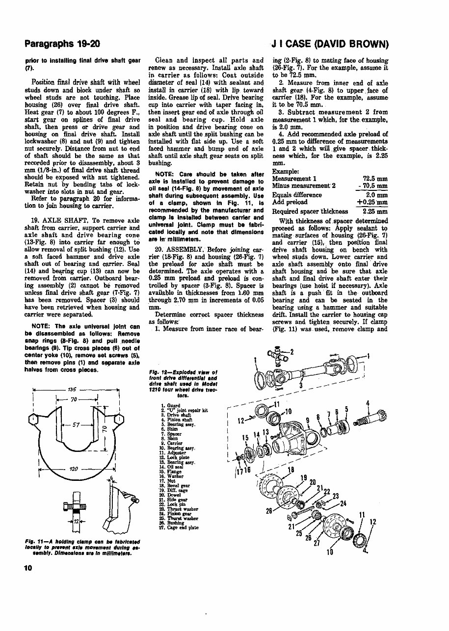
Fig. 12-Exploded "ltw 01
"ont d,I", dln,,,,,u., and
dr'". sh.r, and In Mod.,
1210 'our wh"' drl". t,.c>-
to".
1. Guard
2. "U" joint repair kit
3. Drive sbaft;
4. Pinion shaft
i: ~gBB!lY.
7. Sp,"""
8. Shim
9. Carrier
10. Bearing- usr.
11. A_
12. LoCkpiate
13. Beorliig US'!.
14. on seal
15. Flange
16. Washer
17. Nut
18. Bevel gear
"19. niH. cage
20; Dowel
21. Side gear
22. Loekpin
29. 1'bl'IJst washer
1M. PbUon gear
25. Tbunt washer
26. Busbing
'11. Cage end plate
J I CASE (DAVID BROWN)
ing (2-Fig. 8) to mating face of housing
(26·Fig. 7). Fo~ the example. assume it
to he 72.5 mID.
2. Measure from inner end of axle
shaft gear 14.Fig. 8) to upper face of
carrier (18). For the example. assume
it to he 70.5 mm.
3. Subtract measurement 2 from
measurement 1 which. for the example.
is 2.0 mm.
4. Add recommended axle preload of
0.25 mm to difference of measurements
1 and 2 which will give spacer,thick·
ness which. for the example. is 2.26
mm.
Example:
Measurement 1
Minus measurement'2
Equals difference
Add preload
Required spacer ~
72.5mm
- 70.5 mm
2.0mm
+0;25'mm
2.26mm
With thickness of spacer determined
proceed as follows: Apply sealant to
mating surfaces of housing (26-Fig. 7)
and carrier (15), then position final
drive sboft housing on bench with
wheel st\lds down. Lower_ carrier and
axle shaft assembly onto fmal drive
shaft housing and be sure that axle
shaft and final drive sboft enter their
bearings (use hoist if necessary). Axle
shaft is a push' fit in the outboard
bearing and can he seated in the
bearing using a hammer and suitable
drift. Install the carrier to housing cap
screws and tighten securely. If clamp
(Fig. 11) was -used, remove clamp and
--
You're Reading a Preview
What's Included?
Fast Download Speeds
Online & Offline Access
Access PDF Contents & Bookmarks
Full Search Facility
Print one or all pages of your manual
$31.99
Viewed 19 Times Today


Secure transaction
What's Included?
Fast Download Speeds
Online & Offline Access
Access PDF Contents & Bookmarks
Full Search Facility
Print one or all pages of your manual
$31.99
- The David Brown 885 Tractor Service & Repair Manual is a comprehensive guide designed to assist in addressing any issues that may arise with your tractor.
- It empowers both professional mechanics and DIY enthusiasts with the knowledge and skills needed to perform troubleshooting and replacement procedures recommended by the manufacturer.
- Regular maintenance is crucial for maintaining the durability of your tractor. This manual provides access to the manufacturer's recommended troubleshooting charts and step-by-step instructions, accompanied by clear images and exploded-view illustrations.
- Its digital format allows for easy navigation, searching, bookmarking, and printing, eliminating the hassle of dealing with greasy, torn, or lost pages.
- Compatible with various electronic devices, including PC and Mac computers, Android and Apple smartphones, and tablets, this manual offers convenience and accessibility.
- Adobe Reader, available for free, is all you need to access this manual on your electronic devices.
- By utilizing this manual, you can save on repairs, reduce downtimes, and ensure the smooth operation of your tractor for years to come.


